Table of Contents
Advertisement
Quick Links
Installation, Operation, and Maintenance
IntelliPak™ Commercial Self-
Contained
Signature Series – 20 to 110 Tons
SCWF and SIWF – 20 to 110 Tons
Only qualified personnel should install and service the equipment. The installation, starting up, and servicing of heating, ventilating, and air-conditioning equipment
can be hazardous and requires specific knowledge and training. Improperly installed, adjusted or altered equipment by an unqualified person could result in death or
serious injury. When working on the equipment, observe all precautions in the literature and on the tags, stickers, and labels that are attached to the equipment.
December 2022
SAFETY WARNING
SCXF-SVX01T-EN
Advertisement
Table of Contents

Subscribe to Our Youtube Channel
Related Manuals for Trane Technologies IntelliPak Signature SCWF


Summary of Contents for Trane Technologies IntelliPak Signature SCWF
- Page 1 Installation, Operation, and Maintenance IntelliPak™ Commercial Self- Contained Signature Series – 20 to 110 Tons SCWF and SIWF – 20 to 110 Tons SAFETY WARNING Only qualified personnel should install and service the equipment. The installation, starting up, and servicing of heating, ventilating, and air-conditioning equipment can be hazardous and requires specific knowledge and training.
- Page 2 Introduction Read this manual thoroughly before operating or servicing WARNING this unit. Proper Field Wiring and Grounding Required! Warnings, Cautions, and Notices Failure to follow code could result in death or serious Safety advisories appear throughout this manual as injury. required.
- Page 3 Introduction WARNING its content without obligation to notify any person of such revision or change. Follow EHS Policies! Failure to follow instructions below could result in Trademarks death or serious injury. All trademarks referenced in this document are the trademarks of their respective owners. •...
-
Page 4: Table Of Contents
Table of Contents Overview........8 Installing the Airside Economizer . - Page 5 Table of Contents Surface Mounting Inside Panel..44 VAV Drive Max Output ....51 Wiring the Time Clock ....44 Occupied Sequence .
- Page 6 Table of Contents Water Piping Options ....55 Human Interface Module—Standard on Basic Water Piping ....56 all Units.
- Page 7 Table of Contents Inspecting and Cleaning the Fan ... . 78 Refrigerant Coils ..... . 88 Draining the Waterside Economizer Supply Fan .
-
Page 8: Overview
Overview Signature Series Self-Contained Note: One copy of this document ships inside the control panel of each unit and is customer property. It must Unit Components be retained by the unit’s maintenance personnel. Commercial self-contained units are complete HVAC This manual describes proper installation, operation, and systems used in floor-by-floor applications. -
Page 9: Standard Controls
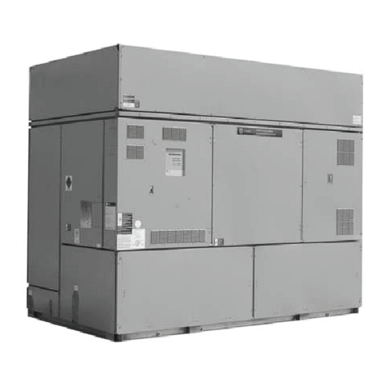
Overview Figure 1. Commercial self-contained signature series unit components Sight glasses with Waterside economizer ports for viewing Unit mounted microprocessor (cleanable option shown) while unit is running control with easy-to-read human Swing out VFO panel with interface panel Tri-VFO for efficient VAV operation 2-inch flat filter box inside unit... -
Page 10: Optional Controls
Overview Optional Controls Figure 2. Right side view of unit Optional controls include a disconnect switch, dirty filter switch, water flow switch (water-cooled only), supply air temperature reset, or external setpoint inputs. Daytime heating is available on units with electric, steam, or hot water heat control options. -
Page 11: Model Number Description
Model Number Description Commercial Self-Contained Signature Series Digit 1 — Unit Model Digit 10, 11 — Design Sequence Digit 17, 18, 19 – Fan RPM S = Self-Contained ** = Factory Assigned 040 = 400 rpm 045 = 450 rpm 050 = 500 rpm Digit 2 —... - Page 12 Model Number Description Digit 25— Industrial Options Digit 32— Miscellaneous System Control A = Protective coating evaporator coil 1 = Time clock B = Silver solder 2 = Interface for remote HI (IPCB) C = Stainless steel screws 3 = Dirty filter switch D = A and B 4 = 1 and 2 E = A and C...
-
Page 13: General Data
General Data Table 1. SCWF/SIWF Water-cooled self-contained, 20 to 42 tons Unit Size Compressor Data Quantity Nominal Ton/comp 15/10 15/10 10/15 Evaporator Coil Data Circuits Rows 3 or 6 4 or 6 4 or 6 Sq. Ft. 21.81 21.81 21.81 29.98 29.98 31.35... - Page 14 General Data Table 2. SCWF/SIWF Water-cooled self-contained, 46-110 tons Unit Size Compressor Data Quantity Nominal Ton/Comp 10/15 15/10 15/10 10/15 Circuits Evaporator Coil Data Rows 4 or 6 4 or 6 4 or 6 6 or 8 6 or 8 6 or 8 Sq.
- Page 15 General Data Table 2. SCWF/SIWF Water-cooled self-contained, 46-110 tons (continued) Unit Size 100/65/ 100/65/30/ 100/71/ 100/71/43/ 100/73/46/ 100/80/40/ 100/75/38/ 100/66/33/ Capacity Steps - % 100/70/41/30/0 32/0 44/24/0 23/0 20/0 20/0 19/0 17/0 Notes: Compressors are Trane 3-D™ scroll. All units operate with R-410A. Units ships with full operating charge. Maximum cfm limits are set to prevent moisture carryover on the evaporator coil.
- Page 16 General Data Table 4. SCWF/SIWF Refrigerant circuits, number of compressors by circuit (continued) Circuit Unit Size 110 Ton 1- 15T 1- 15T 1- 15T 1- 15T 1- 15T 1- 15T Note: This table depicts compressor location in unit, plan view from left corner. Table 5.
- Page 17 General Data Table 7. Waterside economizer coil physical data (continued) Length Type Height (in) (in) Model Unit Size Rows SCXF 29 & 32 Mechanical Cleanable 78.5 SCXF 29 & 32 Mechanical Cleanable 78.5 Chemically Cleanable SCXF 29 & 32 78.5 Chemically Cleanable SCXF 35 &...
-
Page 18: Pre-Installation
Pre-Installation Receiving • Allow three fan diameters above the unit for the discharge ductwork. Return air enters the rear of the Receiving Checklist unit and conditioned supply air discharges through the top. Complete the following checklist immediately after • Electrical connection knockouts are on the top, left side receiving unit shipment to detect possible shipping of the unit. -
Page 19: Unpacking
Pre-Installation • Do not remove damaged material from receiving Important: Do not repair unit until the damage has been location. inspected by the carrier’s representative. • Take photos of the damage, if possible. Unpacking • The owner must provide reasonable evidence that the damage did not occur after delivery. -
Page 20: Unit Protective Covers
Pre-Installation Unit Protective Covers Notes: • There are six fan mounting points for 40-110 Remove shipping protection coverings from human ton units. interface panel (HI) at control panel, filter box (or air inlet opening), discharge air opening, and optional variable •... -
Page 21: Dimensional Data
Dimensional Data Figure 5. 20 to 38 ton self-contained Notes: 1. All unit weights include refrigerant, water, controllers, electric heat and valves. 2. Add 150 lbs. to total weight to obtain approximate shipping weight. SCXF-SVX01T-EN... - Page 22 Dimensional Data Figure 6. 42 to 80 ton self-contained Notes: 1. All unit weights include refrigerant, water, controllers, electric heat and valves. 2. Add 150 lbs. to total weight to obtain approximate shipping weight. SCXF-SVX01T-EN...
- Page 23 Dimensional Data Figure 7. 90 to 110 ton self-contained: front view Plenum (low, standard, and extended height shown) Ext. Height 43.50" Std. Height 27.75" 19.625" Low Height Human VFD/ Interface Interface 89.50" Unit Control 140.00" Figure 8. 90 to 110 ton self-contained: top view (isolator mounting locations shown) 3.50"...
- Page 24 Dimensional Data Figure 9. Detail A: electrical connections 20 to 110 tons 40 3/8” (20-38 Ton) Table 8. Discharge dimensions (in.) Unit Model Fan Size Standard Fan SCWF 20-25 18” 31.85 23.5 23.11 20.4 SCWF 29-32 18” 31.85 23.5 23.11 20.4 SCWF 35-38 20”...
-
Page 25: Steam And Hot Water Coils
Dimensional Data Steam and Hot Water Coils Steam Coils Figure 10. Steam Coil Main Control Panel Vacuum Trap Connection Condensate Return Vacuum Trap Connection Steam Inlet Connection Air Inlet Condensate Return Table 9. Piping locations for steam coils (in.)(lbs) Weight Unit Size 20-38 Ton 60-3/8... -
Page 26: Plenum
Dimensional Data Plenum Table 11. Plenum dimensions (in)(lbs) Weight Unit Model 64-7/8 24-5/8 95-7/8 20-38 Ton std. 64-7/8 32-3/8 95-7/8 ext. 64-7/8 95-7/8 80-3/8 21-1/8 119-7/8 42-80 Ton std. 80-3/8 28-5/8 119-7/8 ext. 80-3/8 119-7/8 80-1/2 19-5/8 90-110 Ton std. 80-1/2 27-3/4 ext. -
Page 27: Airside Economizer
Dimensional Data Airside Economizer Figure 13. Airside economizer Table 13. Airside economizer sizes and dimensions (in.) F (1) F (2) G (1) G (2) H (1) Size SXWF 20 22-3/8 81-3/4 8-3/4 66-3/4 49-3/4 23-1/4 20-1/2 9-3/4 SXWF 22 22-3/8 81-3/4 8-3/4 68-5/8... - Page 28 Dimensional Data Figure 14. Top view of self-contained unit showing Note: (a) See for right side clearance values for various recommended service and code clearances(a) unit configurations. Air Inlet 36” (914.4mm) See Table Minimum Control Panel 42” (1066.8mm) (20-38 Ton) Minimum 48”...
-
Page 29: Weights
Weights Table 15. Unit weights — SCWF/SIWF 2-Row 4-Row Airside Heating 6-Row Evap. Base Weight Waterside Waterside 6-inch filter Unit Economizer Coil Box Coil lbs. Unit lbs. (kg) Economizer Economizer rack lbs. (kg) Size lbs. (kg) lbs. (kg) (kg) lbs. (kg) lbs. -
Page 30: Installation - Mechanical
Installation - Mechanical Unit Handling • Do not stack units. Figure 15. Detail of how to loop chain through lifting WARNING lug on self-contained Improper Unit Lift! Failure to properly lift unit in a LEVEL position could result in unit dropping and possibly crushing operator/technician which could result in death or serious injury, and equipment or property-only damage. -
Page 31: Installation Preparation
Installation - Mechanical Figure 17. Gravity block location and dimensions for 90 to 110 ton units Installation Preparation If job requirements dictate unit isolators, use a housed- spring isolator with a locating pin. Factory-provided unit Before installing the unit, perform the following procedures isolators are type CP and indicate the spring number on the to ensure proper unit operation. -
Page 32: Duct Connections
Installation - Mechanical Figure 18. Optional spring isolator dimensional data Duct Connections Poorly constructed turning vanes may cause airflow generated noise. Align the fan outlet properly with the Return air enters the rear of the unit and conditioned supply ductwork to decrease noise levels in the duct and to air discharges through the top. -
Page 33: Installing The Airside Economizer
Installation - Mechanical Note: Plenum insulation must be applied properly to Figure 21, p. prevent air bypass around the plenum. See Figure 10. Lift the damper cabinet and position it such that the 20, p. hanging bracket is positioned over the unit’s C-channel collar. -
Page 34: Water Piping
Installation - Mechanical Figure 21. Proper lifting of the airside economizer Note: Four (4) condenser waterline drain plugs ship in a (top) and airside economizer option (bottom) bag in the left end of the unit. The installer must field install these four plugs using pipe thread sealer. An additional plug is provided for units with a waterside Spreader economizer. -
Page 35: General Waterside Recommendations
Installation - Mechanical the condensate drain “P” trap drain plug. Before starting compressors will reset when the entering water the unit, fill the trap with water to prevent negative pressure temperature reaches 58°F (15°C). in the fan section from impeding condensate flow. To Units with variable water flow (intermediate piping) have a facilitate drain pipe cleaning, install plugged tees in place of modulating condensing pressure control valve that allows... -
Page 36: Refrigerant Systems
Installation - Mechanical raise the coil box up against the unit and install the the coil to ensure proper operation. mounting screws. Recommended lifting points are at each end of the coil box. Refrigerant Systems 6. Avoid routing wires over devices and sharp edges. Use Trane Water Cooled Commercial Self-Contained units ship wire ties about every 12 inches to secure wires to other factory charged with R-410A refrigerant. -
Page 37: Installation - Electrical
Installation - Electrical Unit Wiring Diagrams Voltage Range Voltages must be within ±10% the nameplate voltage. Specific unit wiring diagrams are provided on the inside of Ensure the unit voltage is balanced by measuring at the the control panel door. Use these diagrams for connections compressor terminals. -
Page 38: Selection Procedures
Installation - Electrical Selection Procedures MFS and MCB = 2.25 x largest motor amps (FLA or RLA) + the sum of the remaining motor amps. RLA = rated load amps For units with the dual power option, there are two Compressor LRA = locked rotor amps electrical circuits that need calculations using the previous Fan motor LRA = locked rotor amps, N.E.C. -
Page 39: Static Pressure Transducer Installation
Installation - Electrical Table 20. Fan motor electrical data (continued) 200V 460V 575V TYPE 59.0 378.0 47.0 305.0 TEFC 59.0 455.0 47.2 380.0 71.0 464.0 Table 21. VFD electrical data Table 23. 2 stage electric heat electrical data VFD L.I.C. 200V 460V 575V... -
Page 40: Zone Sensor Options For Control Units
Installation - Electrical Standard with All Units: BAYSENS077 Note: If plastic tubing pulls away from a connection, trim it back before replacing it on the fitting. Stretched tubing may leak and cause faulty control. Figure 24. Static pressure sensor installation Static Pressure Duct Head Assembly... -
Page 41: Integrated Comfort Systems Sensors For Cv And Vav Applications
Installation - Electrical • Fan control switch to select automatic fan operation • Thumbwheel for local setpoint adjustment while actively heating or cooling (AUTO), or continuous • A cancel button to cancel the “unoccupied override” fan operation (ON). command • Dual temperature setpoint levers for setting desired (Possible Schematic Designation: 5U23) temperature. -
Page 42: Zone Sensor Installation
Installation - Electrical Zone Sensor Installation Notes: • Guidelines for wire sizes and lengths are shown WARNING Table 24, p. 42. The total resistance of these Hazardous Voltage w/Capacitors! low voltage wires must not exceed 2.5 ohms per conductor. Any resistance greater than 2.5 Failure to disconnect power and discharge capacitors ohms may cause the control to malfunction due before servicing could result in death or serious... -
Page 43: Programmable Zone Sensors
Installation - Electrical Figure 26. Typical zone sensor installation heating/cooling functions are enabled/disabled based on set up parameters. As building load changes, If heating/ Mounting Directly to the Wall cooling functions are enabled, the Sensor energizes self- contained unit and evaporator fan operation. The unit will cycle heating/cooling operation throughout the Unoccupied period as required to maintain Unoccupied space temperature setpoints. -
Page 44: Surface Mounting Inside Panel
Installation - Electrical clock power supply. Figure 27. Human interface (HI) panel keypad 4. Since all electronic instruments are sensitive to voltage spikes, pay close attention to the following: a. If possible, supply power to the electronic time clock from a phase different than the one supplying power to the load. -
Page 45: Ambient Temperature And Humidity
Installation - Electrical Table 25. Maximum communication link wiring length bottom end of the panel. b. Remove the recessed hinge screw from the left Max. Capacitance Between hand bottom end of the panel. Max. Wire Length Conductors c. Unlatch the door of the enclosure as if to open it, 1,000 ft up to 60 pf/ft and slide the left hand side of the door upward... -
Page 46: Wiring The Remote Human Interface
Installation - Electrical for the appropriate fasteners, (plastic anchors, molly 6. Place the enclosure back onto the surface and secure it bolts, screws, etc.) with the appropriate screws. 5. Remove the necessary knockouts for the wire or 7. Follow Step 5 in the previous section to replace the conduit entry before mounting the panel. -
Page 47: Low Voltage (Ac) Field Wiring
Installation - Electrical codes. black lead to the negative (-) terminal, and the bare shield wire to the terminal at the remote human • Reference Table 26, p. 45 for recommended wiring interface panel. distance and size. 4. Close the key pad plate and install and tighten the two •... -
Page 48: Communication Wiring
Installation - Electrical Programming the Time Clock Note: Tape the non-insulated end of the shield on shielded wire at the unit. Any connection between the shield Use the following instructions to program the time clock: and ground will cause a malfunction. If daisy- 1. - Page 49 Installation - Electrical indicating the load is permanently off. All days shown in the respective blocks will switch on (or off) at the selected hour and minute. Pressing the “��” key a fourth time returns to automatic, “��” appears in the display. SCXF-SVX01T-EN...
-
Page 50: Operating Principles
Operating Principles Control Sequences of Operation Figure 30. Typical cycling morning warm-up cycle Occupied/Unoccupied Switching • Night setback zone sensor • Field-supplied contact closure (hard wired binary input Ventilation to RTM) Enable • Tracer Summit Morning • Factory-mounted time clock Warmup Temperature Field-Supplied Occupied/Unoccupied... -
Page 51: Timed Override Activation-Ics
Operating Principles Timed Override Activation—ICS™ Zone Temperature Control (Unit Model Number Digit 9 = 4 or 5) This function is operational whenever the unit’s RTM module is used as the zone temperature sensor source, A zone sensor located directly in the space sends input to which can be set at the HI panel. -
Page 52: Cooling/Waterside Economizer
Operating Principles with the highest priority attempts cooling first. Once it is ensure it is greater than 54°F or if not, it will lock out operating at its maximum, and if additional cooling is cooling. necessary, the other economizer enables before Auto Changeover (Units with Heat Only) mechanical cooling begins. -
Page 53: Reset Based On Zone Temperature
Operating Principles Thermostatic Expansion Valve For both outdoor air cooling reset and heating reset, there are three user defined parameters that are adjustable NOTICE through the human interface panel: Compressor Damage! • Beginning reset temperature • Ending reset temperature Do not operate with water loops with less than five minutes circulation time as it could result in poor •... -
Page 54: Compressor Lead/Lag Operation
Operating Principles not turn on until they have been off for at least three The supply air temperature control band is centered around minutes. Normal operating conditions are established on supply air temperature setpoint and is adjustable from 2 to an individual compressor basis. -
Page 55: Compressor Safety Devices
Operating Principles Figure 31. Typical pulldown curve for unit operating mounted on the suction line near the TXV bulb of each properly within control band circuit to protect the evaporator from freezing. If the evaporator temperature approaches the specified setpoint (adjustable between 25 and 35°F at the HI) the compressor(s) will cycle off. -
Page 56: Basic Water Piping
Operating Principles Constant water flow is for condenser pumping systems that approach temperature. The approach temperature default are not capable of unloading the water-pumping system. is 4°F. Waterside economizing disables when the unit’s Variable water flow maximizes energy saving by unloading entering water temperature is not below the unit’s entering the water pumping system. -
Page 57: Unit Airside Components
Operating Principles Unit Airside Components bypass valve either towards open or towards closed respectively. Eventually a balance will be reached until the The air delivery system consists of dampers, enthalpy saturated condenser temperatures change again. Both switch option, airside economizer option, filters, low valves close whenever mechanical cooling is not required, ambient sensors, and factory mounted single or double and in the event of a power failure. -
Page 58: Sensor
Operating Principles Table 30. Supply fan horsepower selections (continued) Unit Model SXRF SXWF 72, 80 90, 100, 110 Low Entering Air Temperature Sensor restart, up to three times. If the over pressurization condition still occurs on the third restart, the unit shuts This is standard on all units with a hydronic coil or down and a manual reset diagnostic sets and displays at waterside economizer. -
Page 59: Comparative Enthalpy Control
Operating Principles Airside Economizers with Traq Damper If the unit does not have an ECEM board, it will economize when the O/A temperature falls below the O/A economizer Outside air enters the unit through the Traq™ damper setpoint. assembly and is measured by velocity pressure flow rings. The mixing box fabrication is galvanized steel. -
Page 60: Airside Economizer Interface With Comparative Enthalpy
Operating Principles suppress setpoint below normal unit setpoint. This allows sequences to allow using outside air for the first stage of the building to improve comfort levels when possible, and cooling, in occupied or unoccupied mode and when at the same time, optimize building mechanical cooling ambient conditions are favorable for economizing. -
Page 61: Controls
Controls Points List ECEM Module Analog Inputs RTM Module • Return air temperature Binary Inputs • Return air humidity • Emergency stop In addition, units with a VOM have: • External auto/stop Binary Inputs • Unoccupied/occupied • VOM mode A, unit off •... -
Page 62: Rtm Module Board-Standard On All
Controls RTM Module Board—Standard on all seconds. This is a manual reset diagnostic, and all heating, cooling, and economizer functions will shut down. If this Units proving input is jumped, other nuisance diagnostics will The RTM responds to cooling, heating, and ventilation occur. - Page 63 Controls When opened, the unit shuts down immediately and can be Table 32. RTM sensor resistance vs. temperature (continued) canceled by closing the switch. Refer to the unit wiring diagrams (attached to the unit control panel) for proper Resistance Resistance connection terminals.
-
Page 64: Compressor Module
Controls Table 34. RTM resistance value vs. system operating The Interprocessor Communication Board expands mode communications from the rooftop unit UCM network to a Remote Human Interface Panel. DIP switch settings on the CV Units VAV Units Resistance applied to IPCB module for this application should be;... -
Page 65: Trane Communications Modules
Controls UNIT OFF Sequence “A” • VO relay—energized When complete system shut down is required, the following • Exhaust fan (field provided -installed)—on sequence can be used. • Exhaust damper (field provided -installed)—open • Supply fan—off PURGE with Duct Pressure Control “E” •... -
Page 66: Ventilation Control Module (Vcm)
Controls to utilize the lowest possible humidity level when Table 35. Minimum outside air setpoint w/VCM module and Traq™ sensing considering economizer operation. In addition, it receives space pressure information which is used to maintain the Input Volts Unit space pressure to within the setpoint control band. Refer to Figure 36, p. - Page 67 Controls with a GBAS and is used to reduce electrical consumption – IPV = (SP - 0.03)(14.8) + 0.5 at peak load times. Demand limiting can be set at either – SP = [(IPV - 0.5)/14.8] + 0.03 50% or 100%. When demand limiting is needed, •...
-
Page 68: Functions
Controls Table 36. GBAS analog input setpoints (continued) Signal Range Vdc Setpoint Range °F Control Parameter Unoccupied zone heating setpoint (CV and VAV) 0.5 to 4.5 50 to 90°F Supply air cooling setpoint (VAV units only) 0.5 to 4.5 40 to 90°F Supply air hydronic heating setpoint (VAV units only) 0.5 to 4.5 40 to 180 F... - Page 69 Controls Return Air Temperature Sensor If the switch is open at start, no compressors on that circuit will operate. They are locked out and a manual reset The return air temperature sensor is an analog input device diagnostic initiates. If the LP switch opens after a used with a return humidity sensor on units with the compressor start, all compressors on that circuit will stop comparative enthalpy option.
- Page 70 Controls • The outside air damper closes pressing the sensor’s reset button when the air temperature decreases approximately 25°F below the • The SERVICE light at the remote zone sensor option cutout point. turns on. Filter Switch • A LEATPD diagnostic displays at the human interface panel.
-
Page 71: Pre-Startup
Pre-Startup Before starting up units, perform the following procedure to To close and reattach the panel, reverse the above ensure proper unit operation. procedures. Note: Verify that all wires are in proper position and not Units with VFD rubbing once the panel has been secured. This panel is hinged to allow service access to fan motor Pre-Startup Checklist and belt drive components that are located behind it. -
Page 72: Electrical
Pre-Startup Electrical Note: Each compressor suction line contains a low pressure sensor that will shut the compressor • Verify electrical connections are tight. down in low pressure situations. See Table 28, p. Components • Ensure system components are properly set and installed. -
Page 73: Start-Up
Start-up WARNING before starting the compressor(s) to close the switch. SLOWLY meter into the suction line only as much R- Live Electrical Components! 410A as needed to close the low pressure cutout. Use Failure to follow all electrical safety precautions when the VAPOR charging connection. -
Page 74: Final Refrigerant Charge
Start-up NOTICE NOTICE Compressor Damage! Compressor Damage! Failure to follow instructions below could result in Failure to follow instructions below could result in compressor damage. compressor failure and/or reduced compressor life. Improper power phasing will cause compressor to run To prevent compressor liquid slugging, only add backwards. -
Page 75: Startup Log
Start-up Startup Log Unit: Unit Location: Unit Voltage Evaporator Evaporator fan motor horsepower: Evaporator fan motor amps: Evaporator fan rpm (actual): Evaporator system static (from test and balance Supply duct static: Return duct static: report or actual readings) Evaporator system cfm (test and balance sheet or actual tested): Evaporator Air Conditioners (with all compressor operating) Entering... -
Page 76: Maintenance
Maintenance Service Access Notes: • To secure the panel in the open position during Access unit controls through the front, top left panel. The service procedures, attach the chain mounted panel is secured with two quick- acting fasteners and an to the cabinet frame behind the unit center automatic latch, which require a screwdriver to remove. -
Page 77: Inspecting And Cleaning The Drain
Maintenance Figure 38. Unit filter sizes and placement for SXWF 20 Figure 40. Unit filter sizes and placement for SXWF 90 to 38 tons to 110 tons Without steam or hot water coil Without steam or hot water coil 24 x 24 24 x 24 24 x 24 24 x 24... -
Page 78: Inspecting And Cleaning The Fan
Maintenance Fan Drive 6. Immediately rinse the drain pan thoroughly with fresh water to prevent potential corrosion from the cleaning WARNING solution. Hazardous Voltage w/Capacitors! 7. Allow the unit to dry thoroughly before putting the system back into service. Failure to disconnect power and discharge capacitors before servicing could result in death or serious 8. -
Page 79: Fan Bearings
Maintenance Figure 41. Fan shaft and motor sheave alignment Table 40. Compatible with NLGI grade 2 lithium fan bearing greases Recommended Grease Recommended Operating Range FINA LICAL Shell Alvania EP2 20°F to 205°F Mobile SHC 220 Fan Belt Tension Note: Check fan belt tension at least twice during the first days of new belt operation since there is a rapid decrease in tension until belts are run-in. -
Page 80: Adjusting Belt Tension
Maintenance Table 41. Fan hub and sheave torques (continued) To adjust belt tension see Figure 42, p. 80 and perform the following procedure: Unit size Fan Diameter Set Screw Torque (ft- 1. Loosen bolts A, B, and E on both sides of the sliding Size lbs) motor base. - Page 81 Maintenance Figure 43. Location of fan belt label on fan scroll (top) and belt tensioning with fan adjustment points (bottom) SCXF-SVX01T-EN...
-
Page 82: Compressors
Maintenance Refrigerant Leak Test Procedure Figure 44. Right-side view of the self-contained unit WARNING Confined Space Hazards! Failure to follow instructions below could result in death or serious injury. Do not work in confined spaces where refrigerant or other hazardous, toxic, or flammable gas may be leaking. -
Page 83: Brazing Procedures
Maintenance Brazing Procedures WARNING R-410A Refrigerant under Higher WARNING Pressure than R-22! Explosion Hazard and Deadly Gases! Failure to use proper equipment or components as Failure to follow all proper safe refrigerant handling described below, could result in equipment failing and practices could result in death or serious injury. -
Page 84: System Evacuation Procedures
Maintenance sound and gas-tight connection. • Open Valves B and C. Evacuate system to a pressure of 300 microns or less. As vacuum is being pulled on 9. Visually inspect the connection after brazing to locate system, it may appear that no further vacuum is being any pinholes or crevices in the joint. -
Page 85: Compressors
Maintenance Figure 46. Evacuation time vs. pressure rise 1600 Continously increasing pressure indicates the presence of leaks, 1400 moisture, or both. 1200 State of equilibrium indicates the 1000 true amount of moisture left in the system. It indicates that no leaks, but requires further evacuation. -
Page 86: Components
Maintenance Components Figure 47. Typical water-cooled compressor section components Note: Tighten bolts to 38 ft. lbs. SCXF-SVX01T-EN... -
Page 87: Cleaning Coil Fin
Maintenance Cleaning Coil Fin the left or right rear side of the unit. • If the refrigerant coil is installed back to back with the WARNING waterside economizer coil, use a cleaner that is Hazardous Chemicals! acceptable for cleaning both types of coils. Failure to follow this safety precaution could result in Inspecting and Cleaning Coils death or serious injury. -
Page 88: Refrigerant Coils
Maintenance Refrigerant Coils drain the condensers. Be sure to open the vent plugs at the top of the condenser inlet and outlet manifold. See . WARNING When refilling the condenser/waterside economizer coil Hazardous Voltage w/Capacitors! system with water, provide adequate water treatment to prevent the formation of scale or corrosion. -
Page 89: Chemical Cleaning Of Condenser And Economizer Coil
Maintenance Maintenance Periodic Checklists Chemical Cleaning of Condenser and Economizer Coil WARNING Chemical cleaning removes scale deposits built up by Hazardous Service Procedures! minerals in the water. For a suitable chemical solution, Failure to follow all precautions in this manual and on consult a water treatment specialist. -
Page 90: Semi-Annual Maintenance
Maintenance 8. Check and record operating pressures. sheaves. 1. Inspect, clean, and tighten all electrical connections. Semi-Annual Maintenance 2. Visually inspect the entire unit casing for chips or 1. Verify the fan motor is properly lubricated. Follow corrosion. Remove rust or corrosion and repaint lubrication recommendations on the motor tag or surfaces. -
Page 91: Diagnostics
Diagnostics Troubleshooting charge, malfunctioning of expansion valves, damaged compressors, etc. will result in pressure variations which System Checks are outside the normal range. Note: If phasing at the main incoming power terminal is WARNING incorrect, switch two of the three incoming power Live Electrical Components! leads. -
Page 92: Additional Diagnostic Resources
Diagnostics Additional Diagnostic Resources Menu” and “Diagnostic Menu” sections in the programming guide. Refer to the following text for general diagnostic and Refer to the Self-Contained Programming Guide, PKG- troubleshooting procedures. SVP01, for specific unit programming and troubleshooting information. In particular, reference the “Service Mode Category Diagnostic Auto Reset S/A Static Pressure Limit... - Page 93 Diagnostics Category Diagnostic Condenser Temp Sensor Failure—Circuit 1, 2, 3, or 4 The saturated condenser temperature input is out of range for circuit #1, 2, 3, or 4. Problem Sensor resistance should be between 830 ohms (200°F) and 345.7 ohms (-40°F). If so, check field/unit wiring between sensor and MCM/SCM. Check Reason for The unit is reading a signal that is out of range for the circuit #1, 2, 3, or 4 saturated condenser temperature sensor.
- Page 94 Diagnostics Category Diagnostic Time to React 10 sec < T < 20 sec Diagnostic Text (Human “ENT COND WATER TEMP SENSOR FAIL” Interface Display) Actions to be A “Lockout All Ckts” request is issued to the “Compressor Staging Function” Initiated An automatic reset occurs after the entering condenser water temperature input returns to within range continuously for 15 seconds.
- Page 95 Diagnostics Category Diagnostic Heat Failure The heat has failed. (Electric heat unit)Typically, this is because the electric heat section became too hot. Problem The heat fail input on the heat module was closed: Reason for • For more than 80 seconds, Diagnostic •...
- Page 96 Diagnostics Category Diagnostic Low Pressure Control Open—Circuit 1, 2, 3, or 4 The Low Pressure Control (LPC) for Ckt #1, 2, 3, or 4 is open. Problem State of refrigerant charge for ckt #1, 2, 3, or 4. Check Reason for The Ckt # 1 LPC input is detected open as described in the compressor protection function.
- Page 97 Diagnostics Category Diagnostic If have an external sensor connected to the NSB panel zone sensor input, then the internal NSB panel zone sensor should be disabled. Verify Check sensor resistance. If in valid range, check wiring between the sensor and NSB panel. NSB Panel Comm Failure The RTM has lost communications with the night setback panel (programmable zone sensor).
- Page 98 Diagnostics Category Diagnostic Reason for The unit is reading a signal that is out of range for the return air humidity sensor (humidity < 5% or humidity > 100%). Diagnostic The economizer enable r.e. enthalpy function reverts to reference enthalpy changeover (“Level 2”) control. Reaction Reset (PMR) An automatic reset occurs after the RA humidity input returns to its allowable range continuously for 10 seconds.
- Page 99 Diagnostics Category Diagnostic Reason for The RTM has lost communication with the SCM. Diagnostic A “lockout” request is sent to the compressor staging control function. A fail-safe function in the SCM will cause all SCM outputs to be zeroed Controls and de-energized.
- Page 100 Diagnostics Category Diagnostic Controls The default HI-set SA temp heating setpoint becomes the active SA temp heating setpoint. Reaction Reset (PAR) An automatic reset occurs after the SA temp heating setpoint input returns to within range for 10 continuous seconds, or after a different Required SA temp heating setpoint selection source is user-defined.
- Page 101 Diagnostics Category Diagnostic The INFO diagnostic is cleared when the supply fan VFD bypass is deactivated. Reset LCI Module Comm Failure Problem The RTM has lost communication with the LCI. Check field/unit wiring between RTM and LCI module. Check Reason for The RTM has lost communication with the LCI module.
- Page 102 Diagnostics Category Diagnostic Controls The active unoccupied zone heating setpoint reverts to the default value. Reaction Reset (PAR) An automatic reset occurs after the designated unoccupied zone heat setpoint input returns to its allowable range for 10 continuous Required seconds, or after the user defines a different, valid unoccupied zone heating setpoint selection source. VCM Communication Failure Problem The RTM has lost communication with the VCM.
- Page 103 Diagnostics Category Diagnostic Reset An automatic reset occurs after one complete set of IPC packets is received. Required WSM Mixed Air Temp Sensor Fail Activation Temperature <-50°F or temperature >209°F, and sensor is selected for use by “waterside economizer temperature enable function” or “preheat Conditions function”...
-
Page 104: Wiring Diagrams
Wiring Diagrams Note: For easier access, published unit wiring diagrams lines) will become available via e-Library instead of (individual, separate diagrams for unitary product through wiring manuals after 2007. Description Number Field Wiring Diagram S*WF 20-80T 2307-8257 Schematic Diagram With VFD Single Point Pwr S*WF 20-80T 2307-8258 Schematic Diagram With VFD RTM Module S*WF 20-80T 2307-8260... - Page 105 Wiring Diagrams Description Number Schematic Diagram Heat, Vent Cntrl and GBAS S*WF 90, 100 and 110T 2309-4606 Schematic Diagram ECEM, VOM LCI, IPCB, HI and RHI Mod S*WF 90, 100, and 110T 1213-1732 SCXF-SVX01T-EN...
- Page 106 Notes SCXF-SVX01T-EN...
- Page 107 Notes SCXF-SVX01T-EN...
- Page 108 Trane - by Trane Technologies (NYSE: TT), a global innovator - creates comfortable, energy efficient indoor environments for commercial and residential applications. For more information, please visit trane. com or tranetechnologies.com. Trane has a policy of continuous product and product data improvements and reserves the right to change design and specifications without notice. We are committed to using environmentally conscious print practices.
Need help?
Do you have a question about the IntelliPak Signature SCWF and is the answer not in the manual?
Questions and answers