Table of Contents
Advertisement
Quick Links
Installation, Operation, and Maintenance
Horizontal Classroom Unit
Ventilator
Model HUV
Model Number:
HUV - "C" and later Design Sequence 750 cfm to 2000 cfm
Only qualified personnel should install and service the equipment. The installation, starting up, and servicing of
heating, ventilating, and air-conditioning equipment can be hazardous and requires specific knowledge and training.
Improperly installed, adjusted or altered equipment by an unqualified person could result in death or serious injury.
When working on the equipment, observe all precautions in the literature and on the tags, stickers, and labels that are
attached to the equipment.
February 2023
SAFETY WARNING
UV-SVX004E-EN
Advertisement
Table of Contents
Troubleshooting

Related Manuals for Trane Technologies HUV075


Summary of Contents for Trane Technologies HUV075
- Page 1 Installation, Operation, and Maintenance Horizontal Classroom Unit Ventilator Model HUV Model Number: HUV - “C” and later Design Sequence 750 cfm to 2000 cfm SAFETY WARNING Only qualified personnel should install and service the equipment. The installation, starting up, and servicing of heating, ventilating, and air-conditioning equipment can be hazardous and requires specific knowledge and training.
- Page 2 Introduction Read this manual thoroughly before operating or servicing this unit. WARNING Warnings, Cautions, and Notices Proper Field Wiring and Grounding Required! Safety advisories appear throughout this manual as required. Failure to follow code could result in death or serious Your personal safety and the proper operation of this machine injury.
- Page 3 Introduction WARNING Follow EHS Policies! Failure to follow instructions below could result in death or serious injury. • All Trane personnel must follow the company’s Environmental, Health and Safety (EHS) policies when performing work such as hot work, electrical, fall protection, lockout/tagout, refrigerant handling, etc.
-
Page 4: Table Of Contents
Table of Contents Model Number Description Fan Mode Switch Installation ... .37 ....7 Zone Sensor Installation . - Page 5 Table of Contents Setting the Time Clock ....47 Timed Override Control (UC400-B/Symbio™ 400-B) ......78 Installation - Electrical .
- Page 6 Table of Contents Diagnostics (UC400-B/Symbio™ 400-B) . 92 Troubleshooting (Wireless Controls) ..94 Troubleshooting (Tracer® ZN520) ..99 Troubleshooting (UC400-B/Symbio™ 400-B) Troubleshooting (Thermostat) ..102 Troubleshooting (ECM) .
-
Page 7: Model Number Description
Model Number Description Digit 1, 2, 3 — Unit Configuration (Coupled Coil Options) Digit 18 — Damper Configuration DA = 1-row, 12 fpi hot-water coil with HUV= Horizontal Unit Ventilator Field-installed damper actuator 2-row,12 fpi chilled-water coil 100% return air/no damper or Digit 4 —... - Page 8 Model Number Description Digit 21 — Discharge Arrangement Digit 30 - Cooling/Changeover Valve Digit 35 — Heating Auto Flow GPM Type Bar grille discharge None Duct collar discharge per None submittal 2-way, 2 position N.C. Duct collar discharge 3/4 in. 2-way, 2 position N.O.
-
Page 9: General Information
General Information Unit Description Filter: Standard units are equipped with a single 1-inch thick filter (MERV 8) that is accessible without removal of the unit Configuration: This classroom unit ventilator is configured front panel. Filter options include throwaway, MERV 8 and in a horizontal (ceiling mount) configuration. -
Page 10: Unit Ventilator Controls (Options)
General Information Unit Ventilator Controls (Options) During bypass mode, the damper moves to prevent air from traveling through the coil. The damper blade is tightly sealed to Customer Supplied Terminal Interface (CSTI): Units eliminate heat pickup while in the full bypass mode. containing the end device control design will incorporate a pre- A two-position isolation valve control (option) further enhances wired, selected control components to a terminal strip for... -
Page 11: Ecm Application Notes
General Information Automatic Controls MCA/MOP and Power Draw Regardless of type of controls, all Tracer® systems provide a The Trane BLDC motors have variable output but are shipped sequence of operation designed to provide rapid warm-up of at specific settings to deliver proper performance and the room and increase ventilation while offsetting overheating. -
Page 12: Pre-Installation
Pre-Installation Jobsite Inspection Always perform the following checks before accepting a unit: 1. Verify that the nameplate data matches the data on the sales order and bill of lading (including electrical data). 2. Verify that the power supply complies with the unit nameplate specifications. -
Page 13: Dimensions And Weights
Dimensions and Weights Unit Location and Clearances personnel to perform maintenance or repair. Provide sufficient room to make water, and electrical connection(s). Locate the unit in an indoor area. The ambient temperature surrounding the unit must not be less than 45°F. Do not locate WARNING the unit in areas subject to freezing. - Page 14 Dimensions and Weights Figure 3. Horizontal unit ventilator with ducted front discharge dimensional data; sizes 075–150 (dimensions in inches) 2”-DIA K.O. 7/8”-DIA K.O. FOR PIPING FOR ELECTRICAL F.A. UPPER BACK R.A. LOWER BACK 2 3/8” 4 7/8” 17 1/8” 17 1/8” BACK VIEW SIDE VIEW 12 1/8”...
- Page 15 Dimensions and Weights Figure 4. Horizontal unit ventilator with ducted front discharge dimensional data; size 200 (dimensions in inches) 2”-DIA K.O. 7/8”-DIA K.O. FOR PIPING FOR ELECTRICAL F.A. UPPER BACK R.A. LOWER BACK 2 3/8” 4 7/8” 17 1/8” 72” 17 1/8”...
- Page 16 Dimensions and Weights Figure 5. Horizontal unit ventilator with double deflection discharge dimensional data; sizes 075–150 (dimensions in inches) 2”-DIA K.O. 7/8”-DIA K.O. 3/4” FOR PIPING FOR ELECTRICAL 4” R.A. LOWER BACK 2 3/8” 7 1/4” 4 7/8” 5 1/8” 17 1/8”...
- Page 17 Dimensions and Weights Figure 6. Horizontal unit ventilator with double deflection discharge dimensional data; size 200 (dimensions in inches) 2”-DIA K.O. 7/8”-DIA K.O. 3/4” FOR PIPING FOR ELECTRICAL 5” R.A. LOWER BACK 2 3/8” 9 1/4” 4 7/8” 5 1/8” 17 1/8”...
- Page 18 Dimensions and Weights Figure 7. Supply/return air arrangements for the horizontal unit ventilator DIGIT 20 = A DIGIT 20 = F DIGIT 20 = L FA DUCT TOP FA DUCT UPPER BACK 100% RA DUCT LOWER BACK w/RA DUCT LOWER BACK w/RA DUCT LOWER BACK DIGIT 20 = B DIGIT 20 = G...
-
Page 19: Installation - Mechanical
Installation - Mechanical Location Considerations Note: Measurements in Figure 3, p. 14 through Figure 7, p. 18 do not include adjusted leveling legs. Adjustment of leveling legs should be done first. Selecting the appropriate location for installing a unit is very New measurements from the floor should be important. - Page 20 Installation - Mechanical Figure 8. Recess flange installation around horizontal Figure 10. Horizontal unit ventilator with front panel unit ventilator access panel and inlet removed Supply Air Grille Recessing Flange Discharge Panel End Cover Return Air Inlet Grille Access Panel Figure 9.
-
Page 21: Coil Piping And Connections
Installation - Mechanical Coil Piping and Connections • Basic: Union and shut-off ball valve on the supply line. Union, control valve and shut-off ball valve on the return line. The coil headers and drain connections are made within the unit chassis to allow a tight seal and help prevent air leakage •... - Page 22 Installation - Mechanical Figure 12. Piping package layout BASIC 2-WAY 3-WAY 3-way main or 2-way main or auxilliary auxilliary water valve Union water valve Union Ball valve Return connection Ball valve Ball valve Supply Supply connection connection Ball valve Union Union Return Typical...
-
Page 23: Valve And Actuator Operation
Installation - Mechanical Valve and Actuator Operation Piping connection knockouts are shown in Figure 3, p. 14 through Figure 7, p. 18. Field connection types and sizes for • NO and NC actuators are different parts. The 7.4 Cv 3-way units without piping packages are listed below. -
Page 24: Balancing Manual Circuit Setter Valve
Installation - Mechanical Balancing Manual Circuit Setter Valve Figure 15. Manual circuit setter valve, differential pressure vs. flow - 1/2” The manual circuit setter valve is an optional end valve supplied on the return pipe of the factory piping package. The valve allows the operator to regulate water flow through the hydronic coil, balance the water flow through the unit with other units in the piping system, and serves as a shutoff or end valve. -
Page 25: Split System Units
Installation - Mechanical Refrigerant Piping Figure 16. Manual circuit setter valve, differential pressure vs. flow - 3/4” WARNING Explosion Hazard and Deadly Gases! Failure to follow all proper safe refrigerant handling practices could result in death or serious injury. Never solder, braze or weld on refrigerant lines or any unit components that are above atmospheric pressure or where refrigerant may be present. -
Page 26: Steam Piping
Installation - Mechanical Steam Piping Figure 19. Steam valve orientation When air, water or another product is heated, the temperature or heat transfer rate can be regulated by a modulating steam pressure control valve. Since pressure and temperature do not vary at the same rate as load, the steam trap capacity, which is determined by the pressure differential between the trap inlet and outlet, may be adequate at full load, but not some lesser... -
Page 27: Installation - Controls
Installation - Controls Control Options • Board will automatically honor only the appropriate customer request (Heat/Cool) depending on sensed water temperature. Available control options: • Feature can be enabled or disabled with a selector • Customer-supplied terminal interface (CSTI) switch—however, it is set correctly at the factory, •... - Page 28 Installation - Controls Standard Adapter Board Field Connections valve control (main and auxiliary coils), electric heat control and damper control. Figure 24. Standard adapter board field connections Screw terminal blocks provide convenient access to fan controls and to end device control. In addition, a courtesy 10 Vdc supply is provided for use with an external potentiometer or rheostat.
- Page 29 Installation - Controls thermostats MUST be hooked to the correct terminal strip Table 10. CSTI adapter board: switch functions locations (V1 and V2) for the changeover function to work. Switch (L-R) SW1 Cooling Electric Heat / Valve one Valve two Changeover In general, the (CSTI) changeover function will provide cooling Function...
-
Page 30: Thermostat
Installation - Controls Thermostat perform the same as the parameter but will in addition, disable the heating function on electric heat The thermostat is a wall-mounted, field installed option. It can and on the changeover coil heat if there are fan failures. provide three-speed control. - Page 31 Installation - Controls Figure 28. Thermostat wiring System 1 System 2 System 4 Heat Only Cool Only 2-Pipe Seasonal Changeover Black Black Black White White White Heat Heat/Cool Blue Cool Purple Purple Purple Fan High Fan High Fan High Yellow Yellow Yellow Fan Medium...
-
Page 32: Tracer® Zn520 Controller
Installation - Controls Tracer® ZN520 Controller • Only strip away two inches maximum of the outer conductor of shielded cable. ® Tracer® ZN520 controllers are LonTalk devices that interface • Make sure that the 24 Vac power supplies are consistent with the Trane Tracer®... -
Page 33: Wiring Overview Outline
Installation - Controls Wiring Overview Outline WCIs from the factory, verify addresses are set correctly prior to powering the device. The rotary address dials on the UC400-B/Symbio™ 400-B General controller serve one or two purposes depending upon the Instructions network: they are always used for the MAC Address, which is sometimes all or part of the BACnet Device ID (refer to the illustration below). -
Page 34: Power Supply
Installation - Controls BACnet networks with a Tracer® SC system WARNING controller Hazardous Voltage! On BACnet networks with a Tracer® SC system controller, the Device ID for the UC400-B/Symbio™ 400-B controller is Failure to disconnect power before servicing could always soft set by the system controller using the following result in death or serious injury. - Page 35 Installation - Controls • AC transformer requirements: UL listed, Class 2 power transformer, 24 Vac ±15%, device max load 24 VA. The 24 Vac transformer must be sized to provide adequate power to transformer the controller (12 VA) and outputs (maximum 12 VA per A pigtail connection may be necessary between earth ground and/or enclosure binary output).
-
Page 36: Zone Sensor Options
Installation - Controls Zone Sensor Options Figure 34. Unit mtd temp sensor (SP, OALH, COMM) Figure 31. Wireless temp sensor with display (SP, OALH, COMM) Figure 35. Split mtd zone sensor, unit mtd fan speed switch, and wall mtd setpoint dial with On/Cancel Figure 32. -
Page 37: Fan Mode Switch Installation
Installation - Controls • Thick, solid concrete walls between the receiver and the Figure 38. Wall mtd display temp sensor sensor (SP, OCC/UNOCC, OALMH, COMM) • Placing the sensor inside metal enclosures. Location Considerations for Wireless Zone Sensors Placement of the sensor is critical to proper operation (the receiver is factory mounted on fan-coil units). -
Page 38: Zone Sensor Dimensions
Installation - Controls • Unheated or uncooled spaces behind the controller, such 2. Insert the screwdriver blade behind the cover at the top of as outside walls or unoccupied spaces. the module and carefully pry the cover away from the base. •... -
Page 39: Receivers
Installation - Controls Note: Do not use 000 as an address. An address of 000 Figure 41. Mounting zone sensor base plate returns the receiver outputs to their factory defaults (zone temperature and setpoint outputs: 72.5°F, removes all association knowledge, and prevents association with a sensor. -
Page 40: Observing The Receiver For Readiness To Associate
Installation - Controls 3. Record the address and location of the receiver and sensor pair. Observing the Receiver for Readiness to Associate After initial power up, the receiver conducts a channel scan for 20 seconds. During this time, the receiver selects from 16 available channels the clearest channel on which to operate. -
Page 41: Sensor Operations
Installation - Controls Sensor Operations Model WZS sensor Temporary Occupancy (Timed Override) Temporary occupancy (timed override) is available on model WDS. Temporary occupancy is selected for after-business- hours adjustment of temperature setting, fan settings, or heat/ cool settings, when the system has changed to unoccupied mode. -
Page 42: Sensor Transmission Time And Temperature
Installation - Controls • The receiver conducts an energy scan for 20 seconds to – 0.1°C for a model WDS sensor. determine the clearest channel on which to operate. Wireless Sensor Specifications • LED3 flashes On every 2 seconds when it is ready to accept a sensor association request. -
Page 43: Configuring The Wireless Display Sensor (Model Wds Only)
Installation - Controls Configuring the Wireless Display The display will change to configuration mode. When the sensor is in configuration mode, a wrench symbol appears on Sensor (Model WDS only) the display and the menus are separated by lines, as illustrated below. -
Page 44: Displaying Setpoint Or Temperature
Installation - Controls Setting Configuration Options System no system options enabled (Default) auto/off auto/off/ auto/off/low low/high med/high Note: Not all fan options are available for all systems. off/high (on) off/low/high off/low/ no fan options med/high enabled Occupancy (timed override) occupancy occupancy enabled disabled... -
Page 45: Wds Operating Mode
Installation - Controls Changing Room Temperature 1. To increase the room This symbol shows the current room temperature, press temperature, or your Setpoint setpoint selection while To decrease the room you are making an • From the system menu press the down arrow to select temperature, press adjustment. -
Page 46: Requesting Temporary Occupancy
Installation - Controls Requesting Temporary Occupancy Testing Signal Strength • If you need heating or cooling after Select to Indicates Indicates Indicates request excellent satisfactor poor normal business hours, you can occupancy signal y signal signal “request” temporary occupancy by strength strength strength... -
Page 47: Time Clock
Time Clock Setting the Time Clock The Time Clock must be programmed for the unit to operate. If not programmed, the unit may not run in the correct occupied/unoccupied state until timing instructions are received from the Time Clock. Note: Power must be supplied to the unit for the time clock to 1. - Page 48 Time Clock 4. The day display (on the left side of the display screen) Figure 47. Daylight Savings Time begins to blink—use + / - to select the desired setting and press OK. Note: After you set the switching ON time, the prog number should increase by one (for example, from prog 01 to prog 02).
-
Page 49: Installation - Electrical
Installation - Electrical Wiring Important: Do not bundle or run interconnection wiring in parallel with or in the same conduit with any Electrical Wiring high-voltage wires (110 V or greater). Exposure of interconnection wiring to high Unit Wiring Diagrams: Specific unit wiring diagrams, voltage wiring, inductive loads, or RF based on unit options ordered, are provided inside each unit transmitters may cause radio frequency... -
Page 50: Heating Coils With Direct Expansion Cooling
Installation - Electrical Heating Coils with Direct Expansion Cooling WARNING Hazardous Voltage! Failure to disconnect power before servicing could result in death or serious injury. Disconnect all electric power, including remote disconnects before servicing. Follow proper lockout/ tagout procedures to ensure the power can not be inadvertently energized. -
Page 51: Ecm Overview And Setup
ECM Overview and Setup Overview • The BLDC motor has integrated electronics, overload protection and short circuit protection. The motor contains no user-serviceable components inside. This section addresses changes to unit ventilators, integrating new Trane Brushless DC motors and controllers. This exciting NOTICE new series delivers outstanding comfort, safety, and performance with greatly reduced energy consumption... -
Page 52: Status Display
ECM Overview and Setup • The engine integrates a versatile configurable auxiliary The ECM engine board contains a four-digit, seven-segment temperature sensor. display that is used to present information in a format close to real-world language, while having a small-form factor. Most •... -
Page 53: Installation And Initial Setup
ECM Overview and Setup • Wall-mounted low-voltage fan speed switch inputs to the adapter boards’ terminal strips and 24 Vac tap to field- WARNING installed fan speed switch. Safety Alert! • Field-supplied controllers/thermostats to the adapter You MUST follow all instructions below. Failure to do so boards’... -
Page 54: Adjustment And Configuration Of The Engine Board
ECM Overview and Setup Note: Specifications subject to change without notice. The ECM engine board features a nested menu integrated Consult the unit submittals and unit schematics before user interface (UI) that supports: determining hookup requirements unit. Terminal block 1. Status display for instant touch-free confirmation of unit positions, polarities and assignments are determined operation. - Page 55 ECM Overview and Setup Table 15. Operational status codes RPM Mode Indicates the current rpm of Motor 1 in the system. “0” rpm here indicate that no fan RUNNING/ FAN STATUS speed has been requested. CONTINUOUS LOOP ...
- Page 56 ECM Overview and Setup Configuration Examples Figure 51. User interface input buttons Example 1: View the value parameters without saving. Verify the low speed value for motor 1 is set to 800 rpm. Start with the ECM engine scrolling status display and proceed as follows: The user interface has three input buttons, from left to right: 1.
-
Page 57: Initial Setup And Configuration
ECM Overview and Setup Priority / Error Display Under special conditions, the status display will interrupt briefly to prioritize display of events: Notes: • During error displays, the user interface will be disabled, until the error is removed or resolved. •... -
Page 58: Configuration
ECM Overview and Setup • Adjustment and calibration of the variable speed inputs (VSP/0–10V) on the system, where applicable. WARNING • Adjustment, calibration or disabling of the optional auto- Safety Alert! changeover function on CSTI units, where applicable. You MUST follow all instructions below. Failure to do so In addition, the CSTI adapter board offers configurability that could result in death or serious injury. - Page 59 ECM Overview and Setup thermostatic inputs (with adjustable speed), so the use of 4. The ECM engine can accept slightly over-biased inputs up the 0–10V inputs is optional. to 12 Vdc, and the parameter can be set to a value less than 1.0 to compensate.
- Page 60 ECM Overview and Setup Use of Potentiometer/Rheostat For VSP Figure 52. Typical connection WARNING Hazardous Voltage w/Capacitors! Failure to disconnect power and discharge capacitors before servicing could result in death or serious injury. Disconnect all electric power, including remote disconnects and discharge all motor start/run capacitors before servicing.
-
Page 61: Configuring The Ecm Engine Board
ECM Overview and Setup The ECM engine board provides additional temperature • When combined with the CSTI adapter board, the bi- controlled logic to help coordinate certain electric-heat and metallic disc temperature switch emulation and the electric valve logic functions: heat lockout function will work when the switches are set correctly. - Page 62 ECM Overview and Setup Configuration Settings of the ECM Engine Board WARNING Safety Alert! You MUST follow all instructions below. Failure to do so could result in death or serious injury. All settings take effect immediately, including fan startup and enabling of electric heat. Caution should be taken to stay clear of hazardous voltages, moving parts and electric heat elements while making adjustments to the ECM engine board.
- Page 63 ECM Overview and Setup Table 18. Configuration settings of the motor control board (for reference only) User Description on Interface Typical User Unit Label Name Interface Value Description Mtr 1 High Spd Sets the high-speed rpm for Motor 1. Do not exceed 2300 rpm.
- Page 64 ECM Overview and Setup Table 18. Configuration settings of the motor control board (for reference only) (continued) User Description on Interface Typical User Unit Label Name Interface Value Description Rejects noise on the analog input lines and sets up the ...
- Page 65 ECM Overview and Setup Table 18. Configuration settings of the motor control board (for reference only) (continued) User Description on Interface Typical User Unit Label Name Interface Value Description Do NOT change this setting. This setting locks out the following parameters from being changed, for safe operation of the unit.
-
Page 66: Pre-Start
Pre-Start Before energizing the unit, the following system devices must be checked: Is the high voltage power supply correct and in accordance with the nameplate ratings? Is the field wiring and circuit protection the correct size? Is the low voltage control circuit wiring correct per the unit ... -
Page 67: Startup
Startup Unit Startup 5. 4-Pipe Auto Changeover is for a 4 pipe system. The user selects whether the system will be set to heat, cool, heat and cool or OFF. Thermostat • “1” Heat only Thermostat Operation • “2” Cool only Auto: Fan will automatically adjust the fan speed (Low, •... - Page 68 Startup 9 – Pipe Sensor Delay Time • “S” Display set point only • “r” Display room temperature only This is the time that the valve will be open to verify the pipe temperature before the valve is turned off. This gives time for •...
-
Page 69: Tracer® Zn520 Unit Startup
Startup button. The word FAN shows on the display and the fan The appropriate control valve will actuate assuming the icon appears when the fan operates. following conditions: 1. Room temperature should be greater than 55°F and less Heat Mode than 85°F. -
Page 70: General Information
Startup Tracer® ZN520 Sequence of General Information Operation Fan Mode Switch Operation The Tracer® ZN520 operates the fan in the following modes: Fan is turned OFF, two-position damper option spring-returns 1. occupied closed. 2. unoccupied Hi, Med, Lo 3. occupied standby Fan runs continuously at the selected speed. -
Page 71: Cooling Operation (Tracer® Zn520)
Startup During occupied standby mode, the controller’s economizer retained until the unit power is disconnected. Refer to Trane damper position goes to the economizer standby minimum publication, CNT-SVX04*-EN for specific instructions position. The economizer standby minimum position can be regarding the procedure for running the Tracer® ZN520. changed using Rover service tool. -
Page 72: Fan Mode Operation (Tracer® Zn520)
Startup Discharge Air Tempering (Tracer® ZN520) only used for ventilation; therefore, the damper is at the occupied minimum position in the occupied mode. The damper The discharge air tempering function enables when cold control is primarily associated with occupied fan operation. outdoor air is brought in through the outdoor air damper, causing the discharge air to fall below the discharge air Fan Mode Operation (Tracer®... - Page 73 Startup Fan Start on High Speed (Tracer® ZN520) Table 21. Fan operation in heating and cooling modes (Tracer® ZN520) On a transition from off to any other fan speed, the Tracer® ZN520 controller automatically starts the fan on high speed Heating Cooling and runs the fan at high speed for 0.5 seconds.
- Page 74 Startup control and effectively disables entering water temperature Table 23. Relationship between outdoor temperature sensors and damper position (Tracer® ZN520) sampling until it is required. Electric Heat Operation (Tracer® ZN520) Outdoor Air Modulating Outdoor Air Damper Temp. The Tracer® ZN520 controller supports one or two-stage Occupied or electric heat operation for heating.
- Page 75 Startup Each binary input default configuration (including normally Table 25. Binary output configuration (Tracer® ZN520) open/closed) is set at the factory. However, you can configure each of the four binary inputs as normally open or normally Binary Configuration closed. The controller will be set properly for each factory- Output supplied binary input end-device.
- Page 76 Startup Zone Sensor (Tracer® ZN520) When the controller is in unoccupied mode, it always uses the stored unoccupied heating and cooling setpoints.The unit can The Tracer® ZN520 controller accepts the following zone also be configured to enable or disable the local (hard-wired) sensor module inputs: setpoint.
-
Page 77: Uc400-B/Symbio™ 400-B Sequence Of Operation
Startup UC400-B/Symbio™ 400-B • Two terminals for communication from the board to the next unit (daisy chain) Sequence of Operation • Two terminals for a connection from the zone sensor back to the controller UC400-B/Symbio™ 400-B controller will operate to maintain the space temperature setpoint. -
Page 78: Timed Override Control
Startup Occupied Mode (UC400-B/Symbio™ 400-B) Timed Override Control (UC400-B/ Symbio™ 400-B) In Occupied Mode, the UC400-B/Symbio™ 400-B controller maintains the space temperature based on the occupied space If theUC400-B/Symbio™ 400-B controller has a timed override temperature setpoint ± occupied offset. The controller uses the option (ON/CANCEL buttons), pushing the ON button initiates occupied mode as a default mode when other forms of a timed override on request. -
Page 79: Discharge Air Tempering
Startup If the discharge air temperature falls below the discharge active cooling setpoint, respectively. The active heating and air temperature low limit setpoint, (configurable using the cooling setpoints are determined by the occupancy mode of Tracer® TU service tool), and the cooling capacity is at a the controller. -
Page 80: Exhaust Control (Uc400-B/Symbio™ 400-B)
Startup of cascade zone control. In unoccupied mode, the fan controller and daughter board will minimize acoustical cycles. nuisance by balancing changes in fan speed and total fan noise. The controller will fully OPEN cooling and heating Manual Fan Speed Control (UC400-B/ valves before increasing fan speed to meet space temperature Symbio™... -
Page 81: Modulating Outdoor/Return Air Damper (Uc400-B/Symbio™ 400-B)
Startup • Heat/cool changeover with a single valve and coil for 2- state. See below for more information about how the controller pipe applications determines the position of the modulating outdoor air damper. • Cooling or heat, cool changeover with the main valve, and Table 28. -
Page 82: Two-Position Control Of A Modulating Outdoor Air Damper (Uc400-B/Symbio™ 400-B)
Startup capacity. When the outdoor air temperature rises 5°F (2.8°C) continues to dehumidify until the sensed humidity falls below above the economizer enable point, the controller disables the setpoint minus the relative humidity offset. economizing and moves the outdoor air damper back to its Peer-to-peer Communication (UC400-B/ predetermined minimum position, based on the current Symbio™... - Page 83 Startup Freeze Avoidance (UC400-B/Symbio™ 400-B) fan status is reported as OFF whenever the fan is not running. In addition, a fan status switch can be connected to binary input Freeze avoidance is used for low ambient temperature 5 (BI5) to monitor the status of the fan for belt-driven or direct- protection.
-
Page 84: Maintenance
Maintenance WARNING NOTICE: Hazardous Service Procedures! Equipment Damage! Failure to follow all precautions in this manual and on Do not operate unit without filters or grille in place. the tags, stickers, and labels could result in death or Operating the unit without filters or grille in place could serious injury. -
Page 85: Removal Of The Fanboard And Coil Cleaning
Maintenance Figure 57. Removal of screws holding drain pan in Figure 58. Tie wires from the cable chase out of the way place. 4. Disconnect motor wires. 5. Loosen the four bolts (two on each side of the fanboard; Figure 59). -
Page 86: Motor
Maintenance holes in the inner bearing surface. Do not alter the inner bearing in any way. Fill the bearing reservoir every six months with a No. 10 SAE, non- detergent, automotive type oil. Motor The fan motor is an electronically commutated motor. To replace the fan motor, complete the following steps: 1. -
Page 87: Diagnostics And Troubleshooting
Diagnostics and Troubleshooting Troubleshooting Checklist If operating difficulties are encountered, refer to the following table for probable causes and corrective measures. If suggested corrective measures have been taken, and the WARNING trouble still persists, contact the control supplier or the local Trane Sales Office. -
Page 88: Testing (Thermostat)
Diagnostics and Troubleshooting Problem Heating Cooling Cause Correction Room sensor is not properly set. Reset room sensor temperature. Clogged filter. Replace filter. Replace malfunctioning component, or contact the Face and bypass damper, or coil valve is control’s contractor, or if Trane controls, see malfunctioning. - Page 89 Diagnostics and Troubleshooting Resetting Diagnostics (Tracer® ZN520) Table 30. Tracer® ZN520 diagnostics (continued) There are a number of ways in which diagnostics are reset: Diagnostic Fan Other Outputs 1. Automatic reset by the controller Relative humidity Valves Enabled, Fresh air damper Enabled, Electric heat failure Enabled, Baseboard heat Enabled 2.
- Page 90 Diagnostics and Troubleshooting Table 31. Tracer® ZN520 controller diagnostics Table 32. Fan outputs do not energize (Tracer® ZN520) Diagnostic Latching Valves Elec Heat Damper Probable Explanation Cause Auxiliary temp. failure Enabled No action No action No action After power-up, the controller always observes a random start that Condensate overflow Closed Closed...
- Page 91 Diagnostics and Troubleshooting Table 33. Valves stay closed (Tracer® ZN520) Table 35. Electric heat not operating (Tracer® ZN520) Probable Probable Cause Explanation Explanation Cause The controller cycles electric heat on and off to meet the unit Normal operation capacity requirements. Normal The controller opens and closes the valves to meet the unit capacity operation...
-
Page 92: Output Testing And Diagnostics (Uc400-B/Symbio™ 400-B)
Diagnostics and Troubleshooting Output Testing and Diagnostics Table 37. Fresh air damper stays closed (Tracer® ZN520) (UC400-B/Symbio™ 400-B) Probable Explanation Cause This section provides information about the following: The controller opens and closes the fresh air damper based on the Normal controller’s occupancy mode and fan status. - Page 93 Diagnostics and Troubleshooting Manual (Latching) Diagnostics (UC400-B/Symbio™ Table 38. UC400-B/Symbio™ 400-B diagnostics 400-B): Manual diagnostics (also referred to as latching) Diagnostic Diagnostic Probable Cause Consequences cause the unit to shut down. Manual diagnostics can be Type cleared from the UC400-B/Symbio™ 400-B controller in one of •...
-
Page 94: Troubleshooting (Wireless Controls)
Diagnostics and Troubleshooting Troubleshooting (Wireless Figure 61. LED, Test button, and symbol locations on Controls) the sensor Locations of LEDs, Test button, Test Symbols, and Error Codes The receiver for all models has four LEDs: LED1, LED2, LED3, and LED5. Note: To view LEDs on a flush mount receiver on a fan-coil unit, the front panel of the unit must be removed. - Page 95 Diagnostics and Troubleshooting Table 39. Diagnostics on the sensor (wireless controls) Table 41. Observing signal strength on the sensor (wireless controls) Error code LED state when Test button is (WDS sensor Indicates... LED state (WZS Symbol (WDS pressed (WZS sensor) User action Indicates...
- Page 96 Diagnostics and Troubleshooting • On model WDS, push the Test button on the sensor. In For more information on interpreting the LEDs and the display response, a battery test symbol appears on the display. symbols that indicate signal strength, see “Testing Signal The symbol shown indicates battery life expectancy.
- Page 97 Diagnostics and Troubleshooting Battery Installation (Wireless Controls) 9. Set the three rotary address switches (locations S1, S2, S3) on the sensor to the same address as the receiver. 10. Record the address and location of the receiver and sensor WARNING pair.
- Page 98 Diagnostics and Troubleshooting features, it can be manually configured (see “Manual 6. Confirm association and communication by noting LED1, Association (Wireless Controls)). LED2, and LED3 as described in “Testing Signal Strength (Wireless Controls). Servicing and Testing (Wireless Controls) Forcing a Sensor to Transmit (Wireless Controls) If the wireless sensor system is not working as expected, use the tools and procedure described in this section.
-
Page 99: Troubleshooting (Tracer® Zn520)
Diagnostics and Troubleshooting Troubleshooting (Tracer® ZN520) a. All models: Measure between the grounded GND- SIGNAL (black) wire and either the SETPOINT (red) or ZONE (white) wire. Compare resistance measurements to those in Table b. WDS only: Measure between the grounded GND- SIGNAL (black) wire and the FAN/SYSTEM (green) wire. -
Page 100: Troubleshooting (Uc400-B/Symbio™ 400-B)
Diagnostics and Troubleshooting If the LED is off, either the power is off, an abnormal condition Table 48. Test sequence for 1-heat/1-cool configurations is present or the TEST button is pressed. (Tracer® ZN520) (Tracer® ZN520) Yellow COMM LED Cool Heat Output Damper If the LED is off continuously, the controller is not detecting any... - Page 101 Diagnostics and Troubleshooting Table 49. Fan does not energize (UC400-B/Symbio™ Table 51. Valves remain open (UC400-B/Symbio™ 400- 400-B) (continued) B) (continued) Probable Cause Explanation Probable Cause Explanation Even if the controller is configured for continuous fan operation, the Ensure the valves are correctly configured, using the Tracer® TU Valve Unoccupied fan normally cycles with capacity during unoccupied mode.
-
Page 102: Troubleshooting (Thermostat)
Diagnostics and Troubleshooting Troubleshooting (ECM) Table 53. Outdoor air damper remains closed (UC400-B/ Symbio™ 400-B) (continued) (continued) Probable Cause Explanation WARNING The user can communicate a desired operating mode (such as Requested mode Hazardous Voltage w/Capacitors! OFF, heat, or cool) to the controller. If OFF is communicated to the controller, the unit closes the outdoor air damper. -
Page 103: General Information (Ecm)
Diagnostics and Troubleshooting • The mini-access lid on the front of the main control panel system must be powered down before plugging or un- lid has the ECM engine troubleshooting/setup guide plugging connections to the adapter boards, engine affixed to the back of the lid. This guide is unit-specific and boards or motors. - Page 104 Diagnostics and Troubleshooting • Do not short the courtesy 10 Vdc supply to chassis or loads Note: Do not short 24 Vac (pos 1 or pos 2) to that require greater than 10 mA of DC current. chassis; refer to the unit schematic. •...
-
Page 105: Replacing Ecm Components
Diagnostics and Troubleshooting Replacing ECM Components NOTICE Equipment Damage! WARNING Failure to follow this instruction could result in Hazardous Voltage w/Capacitors! equipment damage. The motor harness attached to the single plug to which Failure to disconnect power and discharge capacitors before servicing could result in death or serious injury. -
Page 106: Circuit Modules Replacement Notes/Work Instructions
Diagnostics and Troubleshooting Circuit Modules Replacement Notes/Work Instructions 1. Circuit modules are equipped with nylon standoffs which can either be removed by squeezing the barbs at the rear of the control panel, or squeezing the latch above the circuit module. If the latter method is chosen, the standoffs will be retained on the metal panel. - Page 107 Diagnostics and Troubleshooting 3. Once the light has been activated, click OK on the Softset Figure 65. Rotary Address - Expansion Module dialog box shown in Figure When you click OK, Tracer® TU softsets the engine module IMC address to 99 and the light on the module will turn off.
-
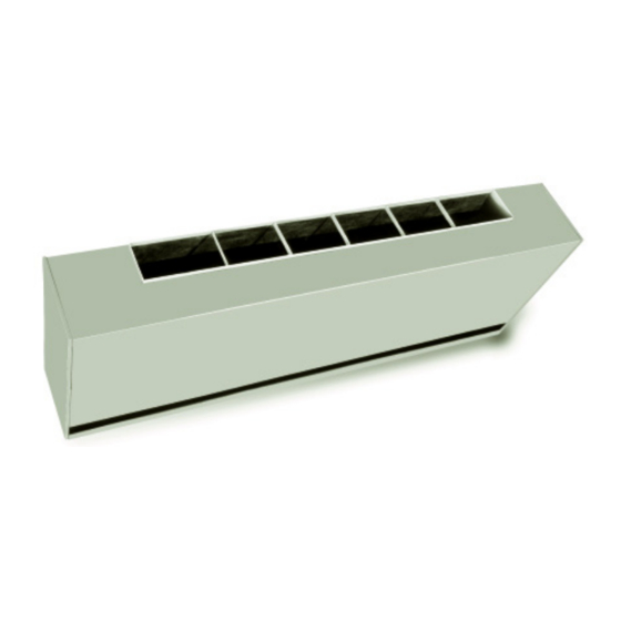
Page 108: Accessories Wallboxes
Accessories Wallboxes General Instructions Trane wallboxes are illustrated below. Each lists the wall The following instructions are general recommendations for openings required for wallboxes. installing wall intake boxes. Consult the architectural plans for Vertical louvers in the wall intake box provide extra strength for specific requirements. - Page 109 Accessories Figure 70. Vertical louver wallbox (V1, V3, V2, and V6) dimensions UV-SVX004E-EN...
-
Page 110: Installation In Curtain Walls
Accessories Installation in Masonry Walls A typical method of installing the wallbox in a masonry wall opening is illustrated below. Grout the top and bottom of the wall box frame as noted. A sloped water dam located in the space between the unit and wall facilitates moisture drainage. -
Page 111: Wiring Diagrams
Wiring Diagrams Table 56. Wiring diagram matrix Number Description Power 2311-4198 Power Schematic, HUV - UC400-B/Symbio™ 400-B Without Electric Heat 2311-4276 Power Schematic, HUV - ZN520 and CSTI Without Electric Heat 4619-4482 Power Schematic, HUV - UC400-B/Symbio™ 400-B With Electric Heat 4619-4483 Power Schematic, HUV - ZN520 and CSTI With Electric Heat Controls... - Page 112 Trane - by Trane Technologies (NYSE: TT), a global climate innovator - creates comfortable, energy efficient indoor environments for commercial and residential applications. For more information, please visit trane.com or tranetechnologies.com. Trane has a policy of continuous product and product data improvement and reserves the right to change design and specifications without notice. We are committed to using environmentally conscious print practices.
Need help?
Do you have a question about the HUV075 and is the answer not in the manual?
Questions and answers