Chapters
Table of Contents

Related Manuals for Stahl 9482/33 Series


Summary of Contents for Stahl 9482/33 Series
- Page 1 Betriebsanleitung Additional languages r-stahl.com Temperatur Input Modul für Zone 2 / Div. 2 Reihe 9482/33...
-
Page 2: Table Of Contents
Inhaltsverzeichnis Allgemeine Angaben ...................3 Hersteller ......................3 Angaben zur Betriebsanleitung ................3 Weitere Dokumente ....................3 Konformität zu Normen und Bestimmungen ............3 Erläuterung der Symbole ..................3 Symbole in der Betriebsanleitung ...............3 Warnhinweise .....................4 Symbole am Gerät ....................4 Sicherheitshinweise ....................5 Aufbewahrung der Betriebsanleitung ..............5 Qualifikation des Personals ................5 Sichere Verwendung ...................5 Umbauten und Änderungen ................6... -
Page 3: De De
Die Originalbetriebsanleitung ist die englische Ausgabe. Diese ist rechtsverbindlich in allen juristischen Angelegenheiten. Weitere Dokumente • Kopplungsbeschreibung IS1+ (Download unter r-stahl.com) • Anleitung "Erdung und Schirmung" (Download unter r-stahl.com) • Datenblatt Dokumente in weiteren Sprachen, siehe r-stahl.com. Konformität zu Normen und Bestimmungen Zertifikate und EU-Konformitätserklärung, siehe r-stahl.com. -
Page 4: 2.2 Warnhinweise
Erläuterung der Symbole Warnhinweise Warnhinweise unbedingt befolgen, um das konstruktive und durch den Betrieb bedingte Risiko zu minimieren. Die Warnhinweise sind wie folgt aufgebaut: • Signalwort: GEFAHR, WARNUNG, VORSICHT, HINWEIS • Art und Quelle der Gefahr/des Schadens • Folgen der Gefahr •... -
Page 5: Sicherheitshinweise
Normen und Bestimmungen umfasst. Für Tätigkeiten in explosionsgefährdeten Bereichen sind weitere Kenntnisse erforderlich! R. STAHL empfiehlt einen Kenntnisstand, der in folgenden Normen beschrieben wird: • IEC/EN 60079-14 (Projektierung, Auswahl und Errichtung elektrischer Anlagen) • IEC/EN 60079-17 (Prüfung und Instandhaltung elektrischer Anlagen) •... -
Page 6: Umbauten Und Änderungen
Sicherheitshinweise • Stromkreise der Zündschutzart "Ex i", die mit Stromkreisen anderer Zündschutzarten betrieben wurden, dürfen danach nicht mehr als Stromkreise der Zündschutzart "Ex i" betrieben werden. • Bei Einsatz in Zone 2 oder Zone 22 ist das Gerät in ein schützendes Gehäuse oder einen Schrank entsprechend der IEC/EN 60079-0 einzubauen, die eine geeignete Schutzart bieten. -
Page 7: Funktion Und Geräteaufbau
Funktion und Geräteaufbau Funktion und Geräteaufbau GEFAHR Explosionsgefahr durch zweckentfremdete Verwendung! Nichtbeachten führt zu schweren oder tödlichen Verletzungen. • Gerät nur entsprechend den in dieser Betriebsanleitung festgelegten Betriebsbedingungen verwenden. • Gerät nur entsprechend dem in dieser Betriebsanleitung genannten Einsatzzweck verwenden. Funktion Einsatzbereich Das Temperatur Input Modul Typ 9482/33 dient zum Anschluss von bis zu... -
Page 8: 4.2 Geräteaufbau
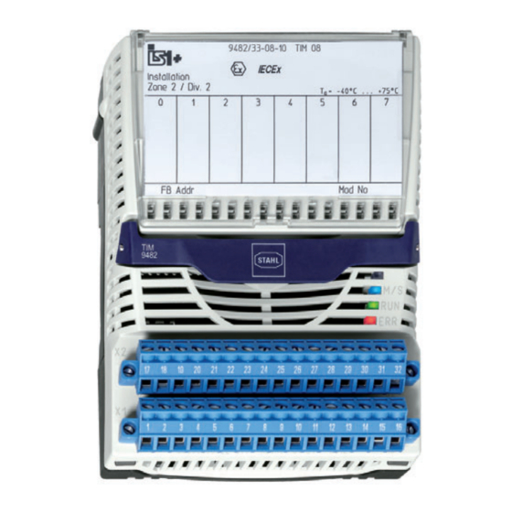
Funktion und Geräteaufbau Geräteaufbau Gerätelement Beschreibung Abdeckklappe Abdeckklappe mit Einlegeschild und Anschlussplan (geöffnet) Beschriftung Angaben zum Modul (Seriennummer, Hardware- Revisionsnummer, Software- Revisionsnummer, Herstelldatum, z.B.: 12345678914-004 Rev. A 01-01 0514) Rasthebel Rasthebel zum Entfernen des Moduls von der BusRail LED zur Anzeige Wartung ("M/S", blau), Betrieb ("RUN", grün) und Fehler ("ERR", rot) -
Page 9: Technische Daten
Technische Daten Technische Daten Explosionsschutz Global (IECEx) Gas und Staub IECEx DEK 13.0046X Ex nA ia [ia Ga] IIC T4 Gc [Ex ia Da] IIIC Europa (ATEX) Gas und Staub DEKRA 13 ATEX 0140 X E II 3 (1) G Ex nA ia [ia Ga] IIC T4 Gc E II (1) D [Ex ia Da] IIIC Bescheinigungen und Zertifikate Bescheinigungen... - Page 10 Technische Daten Technische Daten Einfluss der 0,025 % / 10 K Umgebungs- temperatur Linearität temperaturlinear / widerstandslinear (parametrier- bar) Anschließbare Referenz Messbereich Mittlere Widerstands- (ITS-90) Auflösung thermometer / Widerstands- Pt100 IEC 60751 -200 ... +850 °C 0,1 K geber Pt500 IEC 60751 -200 ...
- Page 11 Technische Daten Technische Daten Reaktionszeit Schaltungs- Betriebsart Betriebsart 4 Kanal schnell 8 Kanal genau Fehlerüberwachung Fehlerüberwachung aktiviert deaktiviert aktiviert deaktiviert 2-Leiter 400 ms 400 ms 750 ms 720 ms 3-Leiter 400 ms 400 ms 750 ms 720 ms 4-Leiter 400 ms 400 ms 750 ms 720 ms...
- Page 12 Technische Daten Technische Daten Reaktionszeit Schaltungs- Betriebsart Betriebsart 4 Kanal schnell 8 Kanal genau Fehlerüberwachung Fehlerüberwachung aktiviert deaktiviert aktiviert deaktiviert Thermo- 2-Leiter 500 ms 450 ms 800 ms 750 ms element 0 ... 100 2-Leiter 500 ms 450 ms 800 ms 750 ms Damit die Zeiten mit "Fehlerüberwachung deaktiviert"...
- Page 13 Technische Daten Technische Daten Galvanische Trennung Prüfspannung gemäß Norm EN 60079-11 Zwischen ) 1500 V AC Hilfsenergie / System- komponenten Zwischen zwei ) 500 V AC I/O-Modulen Zwischen ) 500 V AC I/O-Kanälen / System- komponenten Zwischen ) 500 V AC I/O-Kanälen / Erde (PA) Elektromagnetische...
- Page 14 Technische Daten Technische Daten Gerätespezifische Daten Einstellungen Modul Diagnose- EIN / AUS Meldung Betriebsart 8 Kanal genau / 4 Kanal schnell Auswahl intern / extern 3-Leiter Vergleichsstelle Typ externe PT100, PT1000, PT100 GOST Vergleichsstelle Signal Verhalten im letzten Wert halten Fehlerfall Fehler- EIN / AUS...
- Page 15 Montage / Installation Einbaubedingungen Montageart auf 35 mm DIN-Schiene NS 35/15 (DIN EN 60715) Einbaulage waagrecht oder senkrecht (Betriebsanleitung beachten) Weitere technische Daten, siehe r-stahl.com. 218150 / 948260310020 Temperatur Input Modul für Zone 2 / Div. 2 2019-07-29·BA00·III·de·02 Reihe 9482/33...
-
Page 16: Projektierung
Projektierung Projektierung HINWEIS Ausfall der installierten Geräte im Schaltschrank durch zu hohe Umgebungstemperatur! Nichtbeachten kann zu Sachschäden führen. • Schaltschrank so aufbauen und einrichten, dass er immer innerhalb des zulässigen Temperaturbereichs betrieben wird. Bei der Projektierung folgende Bedingungen beachten: • Installation des Geräts zur bestimmungsgemäßen Verwendung nur auf der IS1 BusRail 9494. -
Page 17: Anschlussbelegung Steckbare Klemmen X1 Und X2
Projektierung Anschlussbelegung steckbare Klemmen X1 und X2 Für das Modul sind zwei steckbare Klemmen X1 und X2 (Schraubklemmen 162702 und 162718 oder Federzugklemmen 162695 und 162716) zum Anschluss von Feldgeräten als Zubehör erhältlich (nicht im Lieferumfang des Moduls enthalten). Die steckbaren Klemmen X1 und X2 haben je 16 Klemmstellen zum Anschluss der Feldkabel. -
Page 18: 6.2 Leitungsfehlerunterdrückung
Projektierung Leitungsfehlerunterdrückung Nicht verwendete Kanäle können zur Unterdrückung von Leitungsfehler-Meldungen optional mit Widerständen (einfaches elektrisches Betriebsmittel für eigensichere Stromkreise gemäß EN 60079-11) beschaltet werden. Die Widerstände sind als Zubehör erhältlich. Je nach Signal-Typ kann wie folgt bestückt werden, z.B. Kanal 0: 2-Leiter TC/Vm-Geber 62R zwischen Klemmstelle 2 und 3 2-Leiter RTD... -
Page 19: Anschlussbeispiel
Projektierung Anschlussbeispiel Anschluss von bis zu 8 Thermoelementen oder mV-Gebern zusammen mit Widerstandsthermometern und externer Vergleichsstelle. Mögliche Mischung unterschiedlicher Signale, z.B.: • Thermoelemente oder mV-Geber am Kanal 0, 2, 6 und 7 • Widerstandsthermometer oder Widerstandsferngeber am Kanal 1, 3 und 5 •... - Page 20 Projektierung 6.4.1 Flussdiagramm zur Auswahl der sicherheitstechnischen Daten 16556E00 Legende = Widerstandsthermometer und / oder Widerstandsferngeber = Thermoelemente und / oder mV-Geber Ext. / Int. CJC = externe / interne Vergleichsstelle ungrounded / = isoliert / geerdet grounded Temperatur Input Modul für Zone 2 / Div. 2 218150 / 948260310020 Reihe 9482/33 2019-07-29·BA00·III·de·02...
- Page 21 Projektierung 6.4.2 Mögliche Beschaltungsarten Die folgenden sicherheitstechnischen Daten gelten nur für die • Beschaltung mit Widerstandsthermometern und Widerstandsgebern (Beschaltungsart A) • Beschaltung mit Thermoelementen und mV-Gebern (Beschaltungsart B – E) • Beschaltungs-Kombinationen mit Widerstandsthermometern und Widerstandgebern sowie Thermoelementen und mV-Gebern (Beschaltungsarten F –...
- Page 22 Projektierung Beschaltungsart A: only RTD, ungrounded 17810E00 Bis zu 8 Widerstandsthermometer oder Widerstandsgeber Hinweis keine Thermoelemente / mV-Geber angeschlossen, keine Vergleichsstelle angeschlossen Installationsart isoliert Max. Ausgangsspannung 6,42 V o ext 2 Leiter 3 Leiter 4 Leiter Max. Strom I 6,5 mA 7,8 mA 9,8 mA Max.
- Page 23 Projektierung Beschaltungsart B: TC with int. CJC, grounded 16553E00 Bis zu 8 geerdete Thermoelemente oder mV-Geber mit interner Vergleichsstelle Installationsart geerdet Vergleichsstelle intern Max. Ausgangsspannung 12,92 V o ext Max. Strom I 25,0 mA Max. Leistung P 81,0 mW Max. Eingangsspannung 6,5 V (für U = 3,5 V siehe Tabelle im Zertifikat) Max.
- Page 24 Projektierung Beschaltungsart D: TC with ext. CJC, grounded 16558E00 Bis zu 8 geerdete Thermoelemente oder mV-Geber mit externer Vergleichsstelle Installationsart geerdet Vergleichsstelle extern Max. Ausgangsspannung 12,92 V o ext Max. Strom I 25,0 mA Max. Leistung P 81,0 mW Max. Eingangsspannung 6,5 V (für U = 3,5 V siehe Tabelle im Zertifikat) Max.
- Page 25 Projektierung Beschaltungsart E: TC with ext. CJC, ungrounded 16496E00 Bis zu 8 isolierte Thermoelemente oder mV-Geber mit externer Vergleichsstelle Installationsart isoliert Vergleichsstelle extern Max. Ausgangsspannung 12,92 V o ext Max. Strom I 6,53 mA Max. Leistung P 21,1 mW Max. Eingangsspannung 6,5 V (für U = 3,5 V siehe Tabelle im Zertifikat) Max.
- Page 26 Projektierung Beschaltungsart F: RTD and TC Mixed with int. CJC, grounded 16560E00 Bis zu 8 geerdete Thermoelemente oder mV-Geber mit interner Vergleichsstelle Installationsart geerdet Vergleichsstelle intern Max. Ausgangsspannung 12,92 V o ext Max. Strom I 25,0 mA Max. Leistung P 81,0 mW Max.
- Page 27 Projektierung Beschaltungsart G: RTD and TC Mixed with int. CJC, ungrounded 16559E00 Bis zu 8 isolierte Thermoelemente oder mV-Geber mit interner Vergleichsstelle Installationsart isoliert Vergleichsstelle intern Max. Ausgangsspannung 12,92 V o ext Max. Strom I 6,53 mA Max. Leistung P 21,1 mW Max.
- Page 28 Projektierung Beschaltungsart H: RTD and TC Mixed with ext. CJC, grounded 16561E00 Bis zu 8 geerdete Thermoelemente oder mV-Geber mit externer Vergleichsstelle Installationsart geerdet Vergleichsstelle extern Max. Ausgangsspannung 12,92 V o ext Max. Strom I 25,0 mA Max. Leistung P 81,0 mW Max.
- Page 29 Projektierung Geerdete externe Vergleichsstelle Installationsart geerdet Vergleichsstelle extern (3 Leiter) Max. Ausgangsspannung 12,92 V o ext Max. Strom I 68,8 mA Max. Leistung P 222,0 mW Max. Eingangsspannung 6,5 V (für U = 3,5 V siehe Tabelle im Zertifikat) Max. anschließbare Kapazität C 0,25 μF 0,27 μF...
-
Page 30: Transport Und Lagerung
Transport und Lagerung Bis zu 8 isolierte Widerstandsthermometer oder Widerstandsgeber Installationsart isoliert Max. Ausgangsspannung 12,92 V o ext 2 Leiter 3 Leiter 4 Leiter Max. Strom I 13,1 mA 15,7 mA 19,6 mA Max. Leistung P 42,2 mW 50,6 mW 63,3 mW Max. -
Page 31: Montage Und Installation
Montage und Installation Montage und Installation Das Gerät ist für den Einsatz in gasexplosionsgefährdeten Bereichen der Zone 2, in staubexplosionsgefährdeten Bereichen der Zone 22 sowie auch im sicheren Bereich zugelassen. Wenn in der Anlage starke elektromagnetische Störquellen vorhanden sind oder die Leitungen länger als 30 m sind, wird empfohlen, geschirmte Feldkabel zu verwenden, um die spezifizierte Genauigkeit zu erreichen. - Page 32 Montage und Installation 2073E00 Montage auf BusRail • Modul senkrecht auf vorgesehenen Steckplatz der BusRail aufsetzen und durch leichtes Drücken einrasten. • Um sicherzustellen, dass das Modul richtig eingerastet ist, nochmals links und rechts das Modul auf die BusRail drücken! Zwischen Modul und BusRail sollte keine Lücke sein! Modul darf sich ohne Betätigen des...
- Page 33 Montage und Installation 8.2.2 Voraussetzungen für Demontage / Modulwechsel Vor der Demontage bzw. dem Wechsel des Moduls Folgendes beachten: • Bei Betrieb im Nicht Ex Bereich ist ein Stecken/Ziehen der Klemmen X1, X2 jederzeit funktionell möglich. Ebenfalls darf auch das Modul auf die BusRail gesteckt oder abgezogen werden (Hot Swap).
-
Page 34: Installation
Montage und Installation Austausch von Modulen Beim Austausch des Moduls durch ein baugleiches Modul werden die eingestellten Parameter übernommen. Es sind keine weiteren Einstellungen notwendig. Beim Austausch des Moduls durch ein Modul mit anderer Funktion meldet das Modul einen Konfigurationsfehler (rote LED "ERR" blinkt). -
Page 35: Inbetriebnahme
Inbetriebnahme Inbetriebnahme Vor Inbetriebnahme Folgendes sicherstellen: • Vorschriftsmäßige Installation des Gerätes. • Richtiger Anschluss der Kabel. • Keine Schäden am Gerät und an Anschlusskabeln. • Fester Sitz der Schrauben an den Klemmen. Richtiges Anzugsdrehmoment: 0,5 ... 0,6 Nm. Abgleich für 2-Leiter-Widerstandsthermometer •... -
Page 36: Potentiometer Im Betrieb "4 Leiter Schnell" (Joystick)
Betrieb Potentiometer im Betrieb "4 Leiter schnell" (Joystick) In dieser Betriebsart werden sehr kurze Signalverzögerungen erreicht, wodurch spezielle Applikationen wie z.B. Joystick möglich sind. • TIM 9482 konfigurieren • Modul Betriebsart auf "4 Kanal R schnell" setzen. • Kanal auf Schaltungsart "4 Leiter" setzen. •... -
Page 37: Fehlerbeseitigung
Ende der Lebensdauer Modulausfall erreicht Wenn sich der Fehler mit den genannten Vorgehensweisen nicht beheben lässt: • An R. STAHL Schaltgeräte GmbH wenden. Zur schnellen Bearbeitung folgende Angaben bereithalten: • Typ und Seriennummer des Geräts • DCS/SPS • Protokoll •... -
Page 38: Instandhaltung, Wartung, Reparatur
GEFAHR Explosionsgefahr durch unsachgemäße Reparatur! Nichtbeachten führt zu schweren oder tödlichen Verletzungen. • Reparaturen an den Geräten ausschließlich durch R. STAHL Schaltgeräte GmbH ausführen lassen. Temperatur Input Modul für Zone 2 / Div. 2 218150 / 948260310020 Reihe 9482/33 2019-07-29·BA00·III·de·02... -
Page 39: Rücksendung
Reinigung 11.4 Rücksendung • Rücksendung bzw. Verpackung der Geräte nur in Absprache mit R. STAHL durchführen! Dazu mit der zuständigen Vertretung von R. STAHL Kontakt aufnehmen. Für die Rücksendung im Reparatur- bzw. Servicefall steht der Kundenservice von R. STAHL zur Verfügung. - Page 41 Operating instructions Additional languages r-stahl.com Temperature Input Module for Zone 2 / Div. 2 Series 9482/33...
- Page 42 Contents General Information ....................3 Manufacturer .......................3 Information regarding the Operating Instructions ..........3 Further Documents .....................3 Conformity with Standards and Regulations ............3 Explanation of the Symbols ................3 Symbols in these Operating Instructions ............3 Warning Notes ....................4 Symbols on the Device ..................4 Safety Notes .......................5 Operating Instructions Storage ................5 Personnel Qualification ..................5...
-
Page 43: En En
They are legally binding in all legal affairs. Further Documents • IS1+ coupling description (download from r-stahl.com) • "Earthing and shielding" instructions (download from r-stahl.com) • Data sheet For documents in additional languages, see r-stahl.com. Conformity with Standards and Regulations See certificates and EU Declaration of Conformity: r-stahl.com. -
Page 44: 2.2 Warning Notes
Explanation of the Symbols Warning Notes Warnings must be observed under all circumstances, in order to minimize the risk due to construction and operation. The warning notes have the following structure: • Signalling word: DANGER, WARNING, CAUTION, NOTICE • Type and source of danger/damage •... -
Page 45: Safety Notes
• Use the device in accordance with its intended and approved purpose only. • Always consult with R. STAHL Schaltgeräte GmbH if using the device under operating conditions which are not covered by the technical data. • Make sure that the device is not damaged. -
Page 46: Modifications And Alterations
Safety Notes • Electrical circuits with the "Ex i" type of protection can no longer be operated as circuits with this protection type after being operated with circuits with other types of protection. • When used in Zone 2 or Zone 22, the device is to be installed in a protective enclosure or in a cabinet that offers a suitable degree of protection in accordance with IEC/EN 60079-0. -
Page 47: Function And Device Design
Function and Device Design Function and Device Design DANGER Explosion hazard due to improper use! Non-compliance results in severe or fatal injuries. • Use the device only in accordance with the operating conditions described in these operating instructions. • Use the device only for the intended purpose specified in these operating instructions. -
Page 48: 4.2 Device Design
Function and Device Design Device Design Device component Description Cover flap Cover flap with insert disc and connection diagram (open) Labelling Module data (serial number, hardware revision number, software revision number, date of manufacture, e.g.: 12345678914-004 Rev.A 01-01 0514) Notch lever Notch lever for removing the module from the BusRail LED for indication... -
Page 49: Technical Data
Technical Data Technical Data Explosion Protection Global (IECEx) Gas and dust IECEx DEK 13.0046X Ex nA ia [ia Ga] IIC T4 Gc [Ex ia Da] IIIC Europe (ATEX) Gas and dust DEKRA 13 ATEX 0140 X E II 3 (1) G Ex nA ia [ia Ga] IIC T4 Gc E II (1) D [Ex ia Da] IIIC Certifications and certificates Certificates... - Page 50 Technical Data Technical Data Ambient 0.025 % / 10 K temperature influence Linearity Temperature linear / resistance linear (adjustable parameters) Connectable Type Reference Measuring range Medium resistance (ITS-90) resolution temperature detectors / Pt100 IEC 60751 -200 to +850 °C 0.1 K resistance Pt500 IEC 60751...
- Page 51 Technical Data Technical Data Reaction time Type Type of Operating mode Operating mode connection 4 channel fast 8 channel accurate Error control Error control Activated Deactiva- Activated Deactiva- 2-conductor 400 ms 400 ms 750 ms 720 ms 3-conductor 400 ms 400 ms 750 ms 720 ms...
- Page 52 Technical Data Technical Data Reaction time Type Type of Operating mode Operating mode connection 4 channel fast 8 channel accurate Error control Error control Activated Deactiva- Activated Deactiva- Thermo- 2-conductor 500 ms 450 ms 800 ms 750 ms couple 0 to 2-conductor 500 ms 450 ms...
- Page 53 Technical Data Technical Data Galvanic separation Test voltage acc. to standard EN 60079-11 Between ) 1500 V AC auxiliary power / system components Between two ) 500 V AC I/O modules Between ) 500 V AC I/O channels / system components Between ) 500 V AC...
- Page 54 Technical Data Technical Data Device-specific data Settings Module Diagnostics ON / OFF message Operating mode 8 channel precise / 4 channel fast Selection internal / external 3-conductor reference junction Type external PT100, PT1000, PT100 GOST reference junction Signal Behaviour in hold last value case of error Error control...
- Page 55 Mounting type On 35 mm DIN rail NS 35/15 (DIN EN 60715) Mounting horizontal or vertical (observe operating instructions) orientation For further technical data, see r-stahl.com. 218150 / 948260310020 Temperature Input Module for Zone 2 / Div. 2 2019-07-29·BA00·III·en·02 Series 9482/33...
-
Page 56: Engineering
Engineering Engineering NOTICE An ambient temperature that is too high may cause failure of the devices installed in the cabinet. Non-compliance can result in material damage. • Install and adjust the cabinet in such a way that it is always operated within the permissible temperature range. -
Page 57: Terminal Assignment Of The Pluggable Terminals X1 And X2
Engineering Terminal Assignment of the pluggable Terminals X1 and X2 For the module, two pluggable terminals X1 and X2 (screw terminals 162702 and 162718 or spring clamp terminals 162695 and 162716) for connection of field devices are available as accessories (not included in the scope of delivery of the module!). The pluggable terminals X1 and X2 have 16 clamping units for connection of the field cables. -
Page 58: 6.2 Line Fault Suppression
Engineering Line Fault Suppression Optionally, non-used channels can be wired to resistors for suppressing line fault indications (simple electrical equipment for intrinsically safe circuits in acc. with EN 60079-11). The resistors are available as accessories. Can be equipped as follows based on the signal type, e.g. channel 0: 2-conductor TC/Vm transmitter 62R between clamping unit 2 and 3 2-conductor RTD... -
Page 59: Connection Example
Engineering Connection Example Up to 8 thermocouples or mV transmitters as well as resistance temperature detectors and an external reference junction are connected. A mixture of different signals is possible, for example: • Thermocouples or mV transmitters on channel 0, 2, 6 and 7 •... - Page 60 Engineering 6.4.1 Flow Chart for Selection of the Safety Data 16556E00 Legend = Resistance temperature detectors and/or resistance temperature detectors = Thermocouples and/or mV transmitters Ext. / int. CJC = External / internal reference junction Unearthed / = Insulated / earthed earthed Temperature Input Module for Zone 2 / Div.
- Page 61 Engineering 6.4.2 Possible Types of Circuitry The following safety data are only applicable to • Circuitry with resistance temperature detectors and resistance transmitters (combination of connection A) • Circuitry with thermocouples and mV transmitters (combinations of connection B – E) •...
- Page 62 Engineering Combination of connection A: only RTD, unearthed 17810E00 Up to 8 resistance temperature detectors or resistance transmitters Note No thermocouples / mV transmitters connected, no reference junction connected Installation type insulated Max. output voltage U 6.42 V o ext 2-conductor 3-conductor 4-conductor...
- Page 63 Engineering Combination of connection B: TC with int. CJC, earthed 16553E00 Up to 8 earthed thermocouples or mV transmitters with internal reference junction Installation type earthed Reference junction internal Max. output voltage U 12.92 V o ext Max. current I 25.0 mA Max.
- Page 64 Engineering Combination of connection D: TC with ext. CJC, earthed 16558E00 Up to 8 earthed thermocouples or mV transmitters with external reference junction Installation type earthed Reference junction external Max. output voltage U 12.92 V o ext Max. current I 25.0 mA Max.
- Page 65 Engineering Combination of connection E: TC with ext. CJC, unearthed 16496E00 Up to 8 insulated thermocouples or mV transmitters with external reference junction Installation type insulated Reference junction external Max. output voltage U 12.92 V o ext Max. current I 6.53 mA Max.
- Page 66 Engineering Combination of connection F: RTD and TC Mixed with int. CJC, earthed 16560E00 Up to 8 earthed thermocouples or mV transmitters with internal reference junction Installation type earthed Reference junction internal Max. output voltage U 12.92 V o ext Max.
- Page 67 Engineering Combination of connection G: RTD and TC Mixed with int. CJC, unearthed 16559E00 Up to 8 insulated thermocouples or mV transmitters with internal reference junction Installation type insulated Reference junction internal Max. output voltage U 12.92 V o ext Max.
- Page 68 Engineering Combination of connection H: RTD and TC Mixed with ext. CJC, earthed 16561E00 Up to 8 earthed thermocouples or mV transmitters with external reference junction Installation type earthed Reference junction external Max. output voltage U 12.92 V o ext Max.
- Page 69 Engineering Earthed external reference junction Installation type earthed Reference junction external (3 conductors) Max. output voltage U 12.92 V o ext Max. current I 68.8 mA Max. power P 222.0 mW Max. input voltage U 6.5 V (for U = 3.5 V, see table in certificate) Max.
-
Page 70: Transport And Storage
Transport and Storage Up to 8 insulated resistance temperature detectors or resistance transmitters Installation type insulated Max. output voltage U 12.92 V o ext 2-conductor 3-conductor 4-conductor Max. current I 13.1 mA 15.7 mA 19.6 mA Max. power P 42.2 mW 50.6 mW 63.3 mW Max. -
Page 71: Mounting And Installation
Mounting and Installation Mounting and Installation The device is approved for use in gas explosion hazardous areas of Zone 2 and dust explosion hazardous area of Zone 22 and in safe areas. If the installation has strong electromagnetic sources of interference or the electrical lines are more than 30 m long, use of shielded field cables is recommended to achieve the specified data. - Page 72 Mounting and Installation 2073E00 Mounting on BusRail • Position the module vertically at the intended slot of the BusRail and press lightly to snap it into place. • Press the module down onto the BusRail to ensure that it is properly secured! There should not be any gap between the module and BusRail! The module must not be able to...
- Page 73 Mounting and Installation 8.2.2 Requirements for Dismounting / Module Replacement Observe the following before dismounting and replacing the module: • During operation in a non-hazardous area, it is functionally possible to insert/remove terminals X1 and X2 at any time. In addition, the module may also be mounted on the BusRail or removed (hot swap).
-
Page 74: Installation
Mounting and Installation Replacing modules When replacing the module with a module with identical design, the set parameters are maintained. No further user adjustments are necessary. When replacing the module with a module with a different function, the module reports a configuration error (red "ERR" LED flashes). The module must be either re-configured or replaced with a module of correct type. -
Page 75: Commissioning
Commissioning Commissioning Before commissioning, ensure the following: • Installation of the device according to regulations. • Correct connection of the cables. • No damage at the device and connection cables. • Tight seat of the screws at the terminals. Correct tightening torque: 0.5 to 0.6 Nm. Compensation for 2-Wire Resistance Temperature Detector •... -
Page 76: Potentiometer In Quick 4-Wire Operation (Joystick)
Operation Potentiometer in quick 4-Wire Operation (Joystick) In this operating mode, very short signal delays are achieved, which allows for special applications, such as joystick applications. • Configuration of TIM 9482 • Set the operating mode of the module to "4 channel R fast". •... -
Page 77: Troubleshooting
If the error cannot be eliminated using the specified procedures: • Contact R. STAHL Schaltgeräte GmbH. For rapid processing, have the following information ready: • Type and serial number of the device •... -
Page 78: Maintenance, Overhaul, Repair
Explosion hazard due to improper repair! Non-compliance results in severe or fatal injuries. • Repair work on the devices must be performed only by R. STAHL Schaltgeräte GmbH. Temperature Input Module for Zone 2 / Div. 2 218150 / 948260310020 Series 9482/33 2019-07-29·BA00·III·en·02... -
Page 79: Returning The Device
• Only return or package the devices after consulting R. STAHL! Contact the responsible representative from R. STAHL. R. STAHL's customer service is available to handle returns if repair or service is required. • Contact customer service personally. • Go to the r-stahl.com website. - Page 81 Nonhazardous Connection allocation example thermocouples or mV-sources and Class I, II, III, Division 2, Group A-G external CJC – Temperature Input Module Type 9482 or Class I, Zone 2, Group IIC/IIB Hazardous (Classified) Locations External External External Thermocouple 2 Wire 3 Wire 4 Wire Terminals...
- Page 82 Entity parameters for wiring configuration – Temperature Input Module Type 9482 General explanations: Grounded - the channels are connected via a common ground together by installation. Ungrounded - the channels are installed galvanically separated to each other and to ground The source is linear in all applications.
- Page 83 Grounded RTD or potentiometer connected in a mixed configuration with Vi For connection of up to 8 passive I.S. circuits. Thermocouples and external CJC circuit might also be connected, their calculation is below. Calculated with the following maximum values: Connector X1 / X2 – Channel 0 (1/4); Channel 1 (5/8) up to Channel 7 (29/32) 2-Wire: Input Voc = 6.42 V...
- Page 84 Ungrounded RTD for external CJC connected in a mixed configuration with Vi For connection of up to 8 passive, galvanically isolated and ungrounded I.S. circuits. Thermocouples and RTD and potentiometer might also be connected, their calculation is above. Calculated with the following maximum values: Connector X2 –...
Need help?
Do you have a question about the 9482/33 Series and is the answer not in the manual?
Questions and answers