Chapters
Table of Contents

Related Manuals for Stahl 9470/32 Series


Summary of Contents for Stahl 9470/32 Series
- Page 1 Betriebsanleitung Additional languages www.r-stahl.com Digital Input Output Modul für Zone 1 Reihe 9470/32...
-
Page 2: Table Of Contents
Inhaltsverzeichnis Allgemeine Angaben ...................3 Hersteller ......................3 Angaben zur Betriebsanleitung ................3 Weitere Dokumente ....................3 Konformität zu Normen und Bestimmungen ............3 Erläuterung der Symbole ..................4 Symbole in der Betriebsanleitung ...............4 Warnhinweise .....................4 Symbole am Gerät ....................5 Sicherheitshinweise ....................5 Aufbewahrung der Betriebsanleitung ..............5 Qualifikation des Personals ................5 Sichere Verwendung ...................6 Umbauten und Änderungen ................7... -
Page 3: De De
2018-07-03·BA00·III·de·02 Die Originalbetriebsanleitung ist die englische Ausgabe. Diese ist rechtsverbindlich in allen juristischen Angelegenheiten. Weitere Dokumente • Kopplungsbeschreibung IS1 (Download unter www.r-stahl.com) • Datenblatt Dokumente in weiteren Sprachen, siehe www.r-stahl.com. Konformität zu Normen und Bestimmungen Zertifikate und EU-Konformitätserklärung, siehe www.r-stahl.com. -
Page 4: Erläuterung Der Symbole
Erläuterung der Symbole Erläuterung der Symbole Symbole in der Betriebsanleitung Symbol Bedeutung Tipps und Empfehlungen zum Gebrauch des Geräts Gefahr durch explosionsfähige Atmosphäre Warnhinweise Warnhinweise unbedingt befolgen, um das konstruktive und durch den Betrieb bedingte Risiko zu minimieren. Die Warnhinweise sind wie folgt aufgebaut: •... -
Page 5: Symbole Am Gerät
Normen und Bestimmungen umfasst. Für Tätigkeiten in explosionsgefährdeten Bereichen sind weitere Kenntnisse erforderlich! R. STAHL empfiehlt einen Kenntnisstand, der in folgenden Normen beschrieben wird: • IEC/EN 60079-14 (Projektierung, Auswahl und Errichtung elektrischer Anlagen) • IEC/EN 60079-17 (Prüfung und Instandhaltung elektrischer Anlagen) •... -
Page 6: 3.3 Sichere Verwendung
• Bei Betriebsbedingungen, die durch die technischen Daten des Geräts nicht abgedeckt werden, unbedingt bei der R. STAHL Schaltgeräte GmbH rückfragen. • Sicherstellen, dass das Gerät unbeschädigt ist. • Für Schäden, die durch fehlerhaften oder unzulässigen Einsatz des Geräts sowie durch Nichtbeachtung dieser Betriebsanleitung entstehen, besteht keine Haftung. -
Page 7: Umbauten Und Änderungen
Funktion und Geräteaufbau Inbetriebnahme, Wartung, Reparatur • Inbetriebnahme und Instandsetzung nur durch qualifizierte und autorisierte Personen (siehe Abschnitt "Qualifikation des Personals") durchführen lassen. • Vor Inbetriebnahme sicherstellen, dass das Gerät unbeschädigt ist. • Nur Wartungsarbeiten durchführen, die in dieser Betriebsanleitung beschrieben sind. •... -
Page 8: Funktion
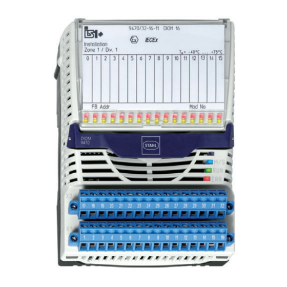
Funktion und Geräteaufbau Funktion Einsatzbereich Das Digital Input Output Modul dient dem Anschluss von bis zu 16 eigensicheren Digitalsignalen an das IS1 Remote I/O-System. Es ist für den Einsatz in explosionsgefährdeten Bereichen der Zone 1, 2, 21, 22 und im sicheren Bereich zugelassen. -
Page 9: Technische Daten
Technische Daten Technische Daten Explosionsschutz Global (IECEx) Gas und Staub IECEx DEK 12.0044X Ex ia [ia Ga] IIC T4 Gb [Ex ia Da] IIIC Europa (ATEX) Gas und Staub DEKRA 12ATEX0099X E II 2 (1) G Ex ia [ia Ga] IIC T4 Gb E II (1) D [Ex ia Da] IIIC USA (FM) in Vorbereitung... - Page 10 Technische Daten Explosionsschutz 2 Kanäle parallel Max. Strom I 20,8 mA Max. Leistung P 51 mW Max. innere 5 nF Kapazität C Max. anschließbare Induktivität L Kapazität C [mH] 100 50 0,02 [μF] 0,44 0,57 0,67 0,77 0,93 1,1 IIB/IIIC [mH] 270 100 50 0,01 [μF]...
- Page 11 Technische Daten Technische Daten Frequenzeingang Max. Anzahl Kanäle Max. 20 kHz (bei Frequenzen > 1 kHz verringert sich die maximale Leitungslänge, Schaltfrequenz z.B. bei 5 kHz auf ca. 75 m) Min. Pulsbreite 25 μs Messbereich 0,1 … 600 Hz 1 Hz … 3 kHz 1 Hz …...
- Page 12 Technische Daten Technische Daten Signalübertragung Max. < 1 мс Verzögerung von Signal / interner Bus Max. Filter ohne klein mittel groß Verzögerung Frequenz Frequenz- eingang / 0,1 Hz ( f < 1 Hz 1/f + 1 ms interner Bus 1 Hz ( f < 10 Hz 1/f + 1 ms 18/f 10 Hz ( f <...
- Page 13 Technische Daten Technische Daten Hilfsenergie Ausführung Eigensicher Ex ia über BusRail Max. 120 mA Stromaufnahme Max. Leistungs- 2,5 W aufnahme Max. 2,5 W Verlustleistung Gerätespezifische Daten Einstellungen Modul Diagnose- EIN / AUS Meldung Signal Signal-Typ Eingang / Ausgang*) Impuls- 0 s / Aus; 0,6 s / Klein; 1,2 s / Mittel; 2,4 s / Groß *) verlängerung / Frequenzfilter Invertieren...
- Page 14 Bei Ausgängen ist Drahtbruch-/Kurzschlusserkennung nur im EIN-Zustand möglich. Montage / Installation Einbaulage waagrecht oder senkrecht (Betriebsanleitung beachten) Montageart auf 35-mm-DIN-Schiene NS 35/15 (DIN EN 60715) Weitere technische Daten, siehe www.r-stahl.com. Digital Input Output Modul für Zone 1 218129 / 9470612310 Reihe 9470/32 2018-07-03·BA00·III·de·02...
-
Page 15: Projektierung
Temperaturbereichs betrieben wird. • "Installationsanleitung Schaltschrank" sorgfältig beachten. Detaillierte Angaben zur Projektierung finden Sie in der "Installationsanleitung Schaltschrank" (Download über www.r-stahl.com, Produktdokumentation, Unterpunkt "Projektierung"). Bei der Projektierung folgende Bedingungen beachten: • Installation des Geräts zur bestimmungsgemäßen Verwendung nur auf der IS1 BusRail 9494. -
Page 16: Betriebsmodus "Frequenz" Oder "Zähler
Grenzsignalgeber Typ 3775 Magnetventil Typ 3962 Magnetventil Typ 3963 Stellungsregler Typ 3766 Festo (Seitz) Magnetventil PV12 F73 Xio H 6,4 V R. Stahl Schaltgeräte LED Leuchtmelder 8010/C1661 Digital Input Output Modul für Zone 1 218129 / 9470612310 Reihe 9470/32 2018-07-03·BA00·III·de·02... -
Page 17: Transport Und Lagerung
Transport und Lagerung Transport und Lagerung • Gerät nur in Originalverpackung transportieren und lagern. • Gerät trocken (keine Betauung) und erschütterungsfrei lagern. • Gerät nicht stürzen. Montage und Installation Das Gerät ist für den Einsatz in gasexplosionsgefährdeten Bereichen der Zonen 1 und 2, in staubexplosionsgefährdeten Bereichen der Zonen 21 und 22 sowie auch im sicheren Bereich zugelassen. -
Page 18: Maßangaben / Befestigungsmaße
Montage und Installation Maßangaben / Befestigungsmaße Maßzeichnungen (alle Maße in mm [Zoll]) – Änderungen vorbehalten 128,5 [5,06] 15254E00 9470/32 Montage / Demontage, Gebrauchslage 8.2.1 Montage / Demontage auf BusRail HINWEIS Fehlfunktion oder Geräteschaden durch unsachgemäße Montage. Nichtbeachten kann Sachschaden verursachen! •... - Page 19 Montage und Installation 8.2.2 Demontage / Modulwechsel GEFAHR Explosionsgefahr durch unzulässigen Betriebszustand des Moduls! Nichtbeachten führt zu schweren oder tödlichen Verletzungen! • Klemme X1 und X2 vom auszutauschenden Modul abziehen, wenn eine Trennwand zum Erreichen des Abstandes von 50 mm montiert ist.
-
Page 20: Installation
Montage und Installation Installation GEFAHR Explosionsgefahr durch falsche Auslegung und Einrichtung von Feldgeräten und Feldstromkreisen! Nichtbeachten führt zu schweren oder tödlichen Verletzungen. • Nationale Errichtungsbestimmungen (z.B.: IEC/EN 60079-14) beachten. • Eigensichere und nicht-eigensichere Feldstromkreise nur in getrennten Kabelkanälen führen, niemals zusammen. •... -
Page 21: Parametrierung Und Inbetriebnahme
Parametrierung und Inbetriebnahme Parametrierung und Inbetriebnahme GEFAHR Explosionsgefahr durch fehlerhafte Installation! Nichtbeachten führt zu schweren oder tödlichen Verletzungen. • Gerät vor der Inbetriebnahme auf korrekte Installation prüfen. • Nationale Bestimmungen einhalten. Vor Inbetriebnahme Folgendes sicherstellen: • Vorschriftsmäßige Installation des Gerätes. •... -
Page 22: Fehlerbeseitigung
16 x LED (gelb) leuchtet Ausgangssignal aktiv lediglich Statusanzeige, keine Maßnahme notwendig Wenn sich der Fehler mit den genannten Vorgehensweisen nicht beheben lässt: • An R. STAHL Schaltgeräte GmbH wenden. Zur schnellen Bearbeitung folgende Angaben bereithalten: • Typ und Seriennummer des Geräts • Kaufdaten •... -
Page 23: Instandhaltung, Wartung, Reparatur
11.3 Reparatur GEFAHR Explosionsgefahr durch unsachgemäße Reparatur! Nichtbeachten führt zu schweren oder tödlichen Verletzungen. • Reparaturen an den Geräten ausschließlich durch R. STAHL Schaltgeräte GmbH ausführen lassen. 218129 / 9470612310 Digital Input Output Modul für Zone 1 2018-07-03·BA00·III·de·02 Reihe 9470/32... -
Page 24: Rücksendung
Reinigung 11.4 Rücksendung • Rücksendung bzw. Verpackung der Geräte nur in Absprache mit R. STAHL durchführen! Dazu mit der zuständigen Vertretung von R. STAHL Kontakt aufnehmen. Für die Rücksendung im Reparatur- bzw. Servicefall steht der Kundenservice von R. STAHL zur Verfügung. - Page 25 Operating instructions Additional languages www.r-stahl.com Digital Input Output Module for Zone 1 Series 9470/32...
- Page 26 Contents General Information ....................3 Manufacturer .......................3 Information regarding the Operating Instructions ..........3 Further Documents .....................3 Conformity with Standards and Regulations ............3 Explanation of the Symbols ................4 Symbols in these Operating Instructions ............4 Warning Notes ....................4 Symbols on the Device ..................5 Safety Notes .......................5 Operating Instructions Storage ................5 Personnel Qualification ..................5...
-
Page 27: En En
• Data sheet For documents in additional languages, see www.r-stahl.com. Conformity with Standards and Regulations See certificates and EU Declaration of Conformity: www.r-stahl.com. The device has IECEx approval. For certificate please refer to the IECEx homepage: http://iecex.iec.ch/ Further national certificates can be downloaded via the following link: https://r-stahl.com/en/global/products/support/downloads/. -
Page 28: Explanation Of The Symbols
Explanation of the Symbols Explanation of the Symbols Symbols in these Operating Instructions Symbol Meaning Tips and recommendations on the use of the device Danger due to explosive atmosphere Warning Notes Warnings must be observed under all circumstances, in order to minimize the risk due to construction and operation. -
Page 29: Symbols On The Device
Specialists who perform these tasks must have a level of knowledge that meets applicable national standards and regulations. Additional knowledge is required for tasks in hazardous areas! R. STAHL recommends having a level of knowledge equal to that described in the following standards: •... -
Page 30: 3.3 Safe Use
• Use the device in accordance with its intended and approved purpose only. • Always consult with R. STAHL Schaltgeräte GmbH if using the device under operating conditions which are not covered by the technical data. • Before installation, make sure that the device is not damaged. -
Page 31: Modifications And Alterations
Function and Device Design Commissioning, maintenance, repair • Only have commissioning and repairs performed by qualified and authorised persons (see "Personnel qualification" section). • Before commissioning, make sure that the device is not damaged. • Perform only maintenance work described in these operating instructions. •... -
Page 32: 4.1 Function
Function and Device Design Function Application range The digital input output module is used for connecting up to 16 intrinsically safe digital signals to the IS1 Remote I/O system. It is approved for use in hazardous areas of Zones 1, 2, 21 and 22 and in safe areas. Mode of operation All channels can be parameterised in pairs as input for connection of passive contacts or NAMUR proximity switches (EN 60947-5-6) or as output for connection of low power... -
Page 33: Technical Data
Technical Data Technical Data Explosion Protection Global (IECEx) Gas and dust IECEx DEK 12.0044X Ex ia [ia Ga] IIC T4 Gb [Ex ia Da] IIIC Europe (ATEX) Gas and dust DEKRA 12ATEX0099X E II 2 (1) G Ex ia [ia Ga] IIC T4 Gb E II (1) D [Ex ia Da] IIIC USA (FM) in preparation... - Page 34 Technical Data Explosion Protection 2 channels in parallel Max. current I 20.8 mA Max. power P 51 mW Max. internal 5 nF capacity C Max. connectable inductance L capacity C [mH] 100 50 0.02 [μF] 0.44 0.57 0.67 0.77 0.93 1.1 IIB/IIIC [mH] 270 100 50 0.01...
- Page 35 Technical Data Technical Data Frequency input Max. number of channels Max. switching 20 kHz (at frequencies > 1 kHz the maximum conductor length is reduced, frequency e.g. at 5 kHz to approx. 75 m) Min. pulse width 25 μs Measuring range 0.1 … 600 Hz 1 Hz …...
- Page 36 Technical Data Technical Data Signal transmission Max. delay < 1 ms from signal / internal bus Max. delay from Filter without small medium large frequency input Frequency / internal bus 0.1 Hz ( f < 1 Hz 1/f + 1 ms 1 Hz ( f <...
- Page 37 Technical Data Technical Data Auxiliary power Version Intrinsically safe Ex ia via BusRail Max. current 120 mA consumption Max. power 2.5 W consumption Max. power 2.5 W dissipation Device-specific data Settings Module Diagnostics ON / OFF message Signal Signal type Input / output*) Pulse 0 s / off;...
- Page 38 Mounting / Installation Mounting orientation horizontal or vertical (observe operating instructions) Mounting type on 35 mm DIN rail NS 35/15 (DIN EN 60715) For further technical data, see www.r-stahl.com. Digital Input Output Module for Zone 1 218129 / 9470612310 Series 9470/32 2018-07-03·BA00·III·en·02...
-
Page 39: Engineering
• Carefully observe the "Cabinet installation guide". You can find detailed information about project engineering in the "Cabinet installation guide" (download from www.r-stahl.com, Product documentation, subitem "Engineering"). The following conditions must be observed during project engineering: •... -
Page 40: Frequency" Or "Counter" Operating Mode
Solenoid valve Type 3962 Solenoid valve Type 3963 Positioner Type 3766 Festo (Seitz) Solenoid valve PV12 F73 Xio H 6.4 V R. Stahl Schaltgeräte LED indicator lamp 8010/C1661 Digital Input Output Module for Zone 1 218129 / 9470612310 Series 9470/32 2018-07-03·BA00·III·en·02... -
Page 41: Transport And Storage
Transport and Storage Transport and Storage • Transport and store the device only in the original packaging. • Store the device in a dry place (no condensation) and vibration-free. • Do not drop the device. Mounting and Installation The device is approved for use in gas explosion hazardous areas of Zones 1 and 2 and dust explosion hazardous area of Zones 21 and 22 and in safe areas. -
Page 42: Dimensions / Fastening Dimensions
Mounting and Installation Dimensions / Fastening Dimensions Dimensional Drawings (All Dimensions in mm [inches]) – Subject to Alterations 128,5 [5,06] 15254E00 9470/32 Mounting / Dismounting, Operating Position 8.2.1 Mounting / Dismounting on BusRail NOTICE Malfunction or device damage caused by improper mounting. Non-compliance may lead to material damage! •... - Page 43 Mounting and Installation 8.2.2 Dismounting / Replacement of the Module DANGER Explosion hazard due to impermissible module operating conditions! Non-compliance results in severe or fatal injuries! • Remove the terminals X1 and X2 from the module to be replaced if a partition is mounted to guarantee a distance of 50 mm. •...
-
Page 44: Installation
Mounting and Installation Installation DANGER Explosion hazard due to incorrect field device and field circuit designs or settings! Non-compliance results in severe or fatal injuries. • Comply with national installation regulations (e.g. IEC/EN 60079-14). • Guide intrinsically safe and non-intrinsically safe field circuits only in separate cable ducts, never together. -
Page 45: Parameterization And Commissioning
Parameterization and Commissioning Parameterization and Commissioning DANGER Explosion hazard due to incorrect installation! Non-compliance results in severe or fatal injuries. • Check the device for proper installation before commissioning. • Comply with national regulations. Before commissioning, ensure the following: • Installation of the device according to regulations. •... -
Page 46: Troubleshooting
16 x LED (yellow) is on Output signal active Purely a status indication, no action required If the error cannot be eliminated using the mentioned procedures: • Contact R. STAHL Schaltgeräte GmbH. For fast processing, have the following information ready: • Type and serial number of the device •... -
Page 47: Maintenance And Repair
DANGER Explosion hazard due to improper repair! Non-compliance results in severe or fatal injuries. • Repair work on the devices must be performed only by R. STAHL Schaltgeräte GmbH. 218129 / 9470612310 Digital Input Output Module for Zone 1 2018-07-03·BA00·III·en·02... -
Page 48: Returning The Device
• Only return or package the devices after consulting R. STAHL! Contact the responsible representative from R. STAHL. R. STAHL's customer service is available to handle returns if repair or service is required. • Contact customer service personally. • Go to the www.r-stahl.com website. - Page 50 Nonhazardous The Type 9470 Digital Input Output Module is designed to receive up Class I, II, III, Division 1, Group A-G to 16 discrete input signals from dry contacts and NAMUR proximity or Class I, Zone 1, Group IIC/IIB sensors etc. and transmit them to the IS1 CPU & Power Module. It is Hazardous (Classified) Locations also possible to drive low power valves.
Need help?
Do you have a question about the 9470/32 Series and is the answer not in the manual?
Questions and answers