Table of Contents
Advertisement
Available languages
Available languages
Quick Links
Advertisement
Chapters
Table of Contents

Related Manuals for Stahl 9477/15 Series


Summary of Contents for Stahl 9477/15 Series
- Page 1 Betriebsanleitung Additional languages r-stahl.com Digital Output Modul Relais Ex nA Ausgänge, 8 Kanäle für Zone 2 / Div. 2 Reihe 9477/15...
-
Page 2: Table Of Contents
Inhaltsverzeichnis Inhaltsverzeichnis Allgemeine Angaben....................3 Hersteller......................3 Angaben zur Betriebsanleitung................3 Weitere Dokumente .....................3 Konformität zu Normen und Bestimmungen ............3 Erläuterung der Symbole ..................4 Symbole in der Betriebsanleitung ................4 Warnhinweise ......................4 Symbole am Gerät ....................5 Sicherheitshinweise .....................5 Aufbewahrung der Betriebsanleitung..............5 Qualifikation des Personals .................5 Sichere Verwendung....................6 Umbauten und Änderungen.................7 Funktion und Geräteaufbau .................8... -
Page 3: En Fr
2023-10-09·BA00·III·de·07 Die Originalbetriebsanleitung ist die deutsche Ausgabe. Diese ist rechtsverbindlich in allen juristischen Angelegenheiten. Weitere Dokumente • Kopplungsbeschreibung IS1+ (Download unter r-stahl.com) • Datenblatt • Nationale Informationen und Dokumente zum Einsatz in explosionsgefährdeten Bereichen (siehe auch Kapitel 1.4) Dokumente in weiteren Sprachen, siehe r-stahl.com. -
Page 4: Erläuterung Der Symbole
Erläuterung der Symbole Erläuterung der Symbole Symbole in der Betriebsanleitung Symbol Bedeutung Tipps und Empfehlungen zum Gebrauch des Geräts Gefahr durch explosionsfähige Atmosphäre Warnhinweise Warnhinweise unbedingt befolgen, um das konstruktive und durch den Betrieb bedingte Risiko zu minimieren. Die Warnhinweise sind wie folgt aufgebaut: •... -
Page 5: Symbole Am Gerät
Normen und Bestimmungen umfasst. Für Tätigkeiten in explosionsgefährdeten Bereichen sind weitere Kenntnisse erforderlich! R. STAHL empfiehlt einen Kenntnisstand, der in folgenden Normen beschrieben wird: • IEC/EN 60079-14 (Projektierung, Auswahl und Errichtung elektrischer Anlagen) • IEC/EN 60079-17 (Prüfung und Instandhaltung elektrischer Anlagen) •... -
Page 6: Sichere Verwendung
• Bei Betriebsbedingungen, die durch die technischen Daten des Geräts nicht abgedeckt werden, unbedingt bei der R. STAHL Schaltgeräte GmbH rückfragen. • Sicherstellen, dass das Gerät unbeschädigt ist. • Für Schäden, die durch fehlerhaften oder unzulässigen Einsatz des Geräts sowie durch Nichtbeachtung dieser Betriebsanleitung entstehen, besteht keine Haftung. -
Page 7: Umbauten Und Änderungen
Sicherheitshinweise Inbetriebnahme, Wartung, Reparatur • Inbetriebnahme und Instandsetzung nur durch qualifizierte und autorisierte Personen (siehe Kapitel "Qualifikation des Personals") durchführen lassen. • Vor Inbetriebnahme sicherstellen, dass das Gerät unbeschädigt ist. • Nur Wartungsarbeiten durchführen, die in dieser Betriebsanleitung beschrieben sind. •... -
Page 8: Funktion Und Geräteaufbau
Funktion und Geräteaufbau Funktion und Geräteaufbau Funktion Einsatzbereich Das Digital Output Modul Relais Typ 9477/15 wird zur Ansteuerung von nicht-eigensicheren Magnetventilen oder Leuchtmeldern eingesetzt. Es dient dem Anschluss von bis zu 8 nicht-eigensicheren Signalen an das IS1+ Remote I/O-System. Das Digital Output Modul Relais Typ 9477/15 ist – bei Einbau in ein entsprechend geeignetes Feldgehäuse –... -
Page 9: Technische Daten
Technische Daten Technische Daten Explosionsschutz Global (IECEx) PTB 06.0001X Ex nA nC nL [ib] IIC T4 Europa (ATEX) PTB 01 ATEX 2187 E II 3 (2) G Ex nA nC ic [ib Gb] IIC T4 Gc Bescheinigungen und Zertifikate Bescheinigungen IECEx, ATEX, Kanada (FM), USA (FM) Schiffszertifikate EU RO Mutual Recognition... - Page 10 Technische Daten Technische Daten Kennwerte Maximale 10 ms Signalverzögerung vom internen Bus zum Ausgang Galvanische Trennung Prüfspannung gemäß Norm EN 60079-11 Zwischen 1500 V AC Hilfsenergie / System- komponenten Zwischen zwei 500 V AC I/O-Modulen zwischen 375 V AC Eingängen / System- komponenten Ausgänge...
- Page 11 Montage / Installation Einbaulage waagrecht oder senkrecht (Betriebsanleitung beachten) Montageart auf 35-mm-DIN-Schiene NS 35/15 (DIN EN 60715) Weitere technische Daten, siehe r-stahl.com. 201521 / 9477605310 Digital Output Modul Relais 2023-10-09·BA00·III·de·07 Ex nA Ausgänge, 8 Kanäle für Zone 2 / Div. 2...
-
Page 12: Projektierung
Projektierung Projektierung HINWEIS Ausfall der installierten Geräte im Schaltschrank durch zu hohe Umgebungstemperatur! Nichtbeachten kann zu Sachschäden führen. • Schaltschrank so aufbauen und einrichten, dass alle darin installierten Geräte immer innerhalb ihres zulässigen Temperaturbereichs betrieben werden. Bei der Projektierung folgende Bedingungen beachten: •... -
Page 13: 7 Transport Und Lagerung
Transport und Lagerung Transport und Lagerung • Gerät nur in Originalverpackung transportieren und lagern. • Gerät trocken (keine Betauung) und erschütterungsfrei lagern. • Gerät nicht stürzen. Montage und Installation Das Gerät ist für den Einsatz in gasexplosionsgefährdeten Bereichen der Zone 2, in staubexplosionsgefährdeten Bereichen der Zone 22 sowie auch im sicheren Bereich zugelassen. -
Page 14: Montage / Demontage, Gebrauchslage
Montage und Installation Montage / Demontage, Gebrauchslage 8.2.1 Montage / Demontage HINWEIS Fehlfunktion oder Geräteschaden durch unsachgemäße Montage. Nichtbeachten kann Sachschaden verursachen! • Gerät nur in vertikaler oder horizontaler Lage montieren und betreiben! (Orientierung horizontal: Lese-Richtung von unten) BusRail BusRail 05683E00 Digital Output Modul Relais 201521 / 9477605310... - Page 15 Montage und Installation Montage auf BusRail • Modul senkrecht auf vorgesehenen Steckplatz der BusRail aufsetzen und durch leichtes Drücken einrasten. • Um sicherzustellen, dass das Modul richtig eingerastet ist, nochmals links und rechts das Modul auf die BusRail drücken! Zwischen Modul und BusRail sollte keine Lücke sein! Modul darf sich ohne Betätigen des Griffs nicht mehr lösen lassen.
- Page 16 Montage und Installation 8.2.2 Voraussetzungen für Demontage / Modulwechsel Vor der Demontage bzw. dem Wechsel des Moduls Folgendes beachten: • Bei Betrieb im Nicht Ex Bereich ist ein Stecken/Ziehen der Klemme X1 jederzeit funktionell möglich. Ebenfalls darf auch das Modul auf die BusRail gesteckt oder abgezogen werden (Hot Swap).
-
Page 17: Installation
Inbetriebnahme Austausch von Modulen Beim Austausch des Moduls durch ein baugleiches Modul werden die eingestellten Parameter übernommen. Es sind keine weiteren Einstellungen notwendig. Beim Austausch des Moduls durch ein Modul mit anderer Funktion meldet das Modul einen Konfigurationsfehler (rote LED "ERR" blinkt). -
Page 18: Anzeigen
LED "ERR" (rot) Modul defekt Modul austauschen leuchtet Wenn sich der Fehler mit den genannten Vorgehensweisen nicht beheben lässt: • An R. STAHL Schaltgeräte GmbH wenden. Zur schnellen Bearbeitung folgende Angaben bereithalten: • Typ und Seriennummer des Geräts • Kaufdaten • Fehlerbeschreibung •... -
Page 19: Cn 11 Instandhaltung, Wartung, Reparatur
• Bestimmungsgemäße Funktion. 11.2 Wartung Das Gerät benötigt keine regelmäßige Wartung. Die geltenden nationalen Bestimmungen im Einsatzland beachten. 11.3 Reparatur Reparaturen an den Geräten ausschließlich durch R. STAHL Schaltgeräte GmbH ausführen lassen. 201521 / 9477605310 Digital Output Modul Relais 2023-10-09·BA00·III·de·07 Ex nA Ausgänge,... -
Page 20: Rücksendung
Reinigung 11.4 Rücksendung • Rücksendung bzw. Verpackung der Geräte nur in Absprache mit R. STAHL durchführen! Dazu mit der zuständigen Vertretung von R. STAHL Kontakt aufnehmen. Für die Rücksendung im Reparatur- bzw. Servicefall steht der Kundenservice von R. STAHL zur Verfügung. - Page 21 Operating instructions Additional languages r-stahl.com Digital output module relay Ex nA outputs, 8 channels for Zone 2/Div. 2 Series 9477/15...
- Page 22 Contents Contents General Information .....................3 Manufacturer......................3 Information regarding the Operating Instructions..........3 Further Documents ....................3 Conformity with Standards and Regulations............3 Explanation of Symbols ..................4 Symbols used in these Operating Instructions.............4 Warning Notes .....................4 Symbols on the Device ..................5 Safety Notes ......................5 Operating Instructions Storage ................5 Personnel Qualification ..................5 Safe Use ......................6...
-
Page 23: En Fr
The original instructions are the German edition. They are legally binding in all legal affairs. Further Documents • IS1+ coupling description (download from r-stahl.com) • Data sheet • National information and documents relating to use in hazardous areas (see also chapter 1.4) For documents in other languages, see r-stahl.com. -
Page 24: Explanation Of Symbols
Explanation of Symbols Explanation of Symbols Symbols used in these Operating Instructions Symbol Meaning Tips and recommendations on the use of the device Danger due to explosive atmosphere Warning Notes Warning notes must be observed under all circumstances, in order to minimise the risk resulting from design engineering and operation. -
Page 25: Symbols On The Device
Additional knowledge is required for any activity in hazardous areas! R. STAHL recommends having a level of knowledge equal to that described in the following standards: • IEC/EN 60079-14 (Electrical installations design, selection and erection) •... -
Page 26: Safe Use
• Use the device in accordance with its intended and approved purpose only. • Always consult R. STAHL Schaltgeräte GmbH if using the device under operating conditions which are not covered by the technical data. • Make sure that the device is not damaged. -
Page 27: Modifications And Alterations
Safety Notes Commissioning, maintenance, repair • Only have commissioning and repairs performed by qualified and authorised persons (see chapter "Personnel qualification"). • Before commissioning, make sure that the device is not damaged. • Only perform the maintenance work described in these operating instructions. •... -
Page 28: Function And Device Design
Function and Device Design Function and Device Design Function Application range The digital output module relay type 9477/15 is used to control non-intrinsically safe solenoid valves and indicator lamps. It is used to connect up to eight non-intrinsically safe signals to the IS1+ Remote I/O system. When installed in a corresponding suitable field enclosure, the digital output module relay type 9477/15 is permitted for use in hazardous areas where gas or dust are present in Zone 2 and Zone 22 or in safe areas. -
Page 29: Technical Data
Technical Data Technical Data Explosion protection Global (IECEx) PTB 06.0001X Ex nA nC nL [ib] IIC T4 Europe (ATEX) PTB 01 ATEX 2187 E II 3 (2) G Ex nA nC ic [ib Gb] IIC T4 Gc Certifications and certificates Certifications IECEx, ATEX, Canada (FM), USA (FM) Ship certificates... - Page 30 Technical Data Technical data Characteristic values Maximum signal 10 ms delay from internal bus to output Galvanic separation Test voltage according to EN 60079-11 standard Between 1500 V AC auxiliary power and system components Between two 500 V AC I/O modules Between inputs 375 V AC and system...
- Page 31 Mounting/installation Mounting orientation horizontal or vertical (observe operating instructions) Mounting type On 35 mm DIN rail NS 35/15 (DIN EN 60715) For further technical data, see r-stahl.com. 201521 / 9477605310 Digital output module relay 2023-10-09·BA00·III·en·07 Ex nA outputs, 8 channels for Zone 2/Div. 2...
-
Page 32: Project Engineering
Project Engineering Project Engineering NOTICE An ambient temperature that is too high may cause failure of the devices installed in the cabinet. Non-compliance can result in material damage. • Install and set up the cabinet in such a way that all devices installed within it are always operated within their permissible temperature range. -
Page 33: 7 Transport And Storage
Transport and Storage Transport and Storage • Transport and store the device only in the original packaging. • Store the device in a dry place (no condensation) free of vibrations. • Do not drop the device. Mounting and Installation The device is approved for use in gas hazardous areas of Zone 2, in dust hazardous areas of Zone 22 and in safe areas. -
Page 34: Mounting/Dismounting, Operating Position
Mounting and Installation Mounting/Dismounting, Operating Position 8.2.1 Mounting/Dismounting NOTICE Malfunction or device damage caused by improper mounting. Non-compliance may lead to material damage. • Only install and operate the device in a vertical or horizontal position. (Horizontal orientation: Reading direction from below) BusRail BusRail 05683E00... - Page 35 Mounting and Installation Mounting on BusRail • Position the module vertically at the intended slot of the BusRail and press lightly to snap it into place. • Press the module down onto the BusRail on the left and right again to ensure that it is properly secured.
- Page 36 Mounting and Installation 8.2.2 Requirements for Dismounting/Module Replacement Observe the following before dismounting or replacing the module: • During operation in a non-Ex area, it is functionally possible to insert/remove terminal X1 at any time. In addition, the module may also be mounted on the BusRail or removed (hot swap).
-
Page 37: Installation
Commissioning Replacing modules When replacing the module with an identical one, the set parameters will be transferred over. No further user adjustments are necessary. When replacing the module with a module with a different function, the module reports a configuration error (red "ERR" LED blinks). Either the module parameters need to be adjusted or a module of the correct type must be used. -
Page 38: Indicators
Replace the module lights up If the error cannot be eliminated using the specified procedures: • Contact R. STAHL Schaltgeräte GmbH. For rapid processing, have the following information ready: • Type and serial number of the device • Purchase information •... -
Page 39: Cn 11 Maintenance, Overhaul, Repair
The device does not require regular maintenance. Observe the relevant national regulations in the country of use. 11.3 Repair Repair work on the devices must be performed only by R. STAHL Schaltgeräte GmbH. 201521 / 9477605310 Digital output module relay 2023-10-09·BA00·III·en·07... -
Page 40: Returning The Device
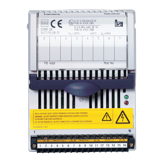
• Only return or package the devices after consulting R. STAHL! Contact the responsible representative from R. STAHL. R. STAHL's customer service is available to handle returns if repair or service is required. • Contact customer service personally. • Go to the r-stahl.com website. - Page 42 Nonhazardous (Unclassified) The Digital Output Module Relay Type 9477/15-08-12 is designed to Class I, Division 2, Groups A, B, C, D or receive a digital signal from the IS1 CPU & Power Module to control up Class I, Zone 2, Group IIC to eight Non-I.S.
Need help?
Do you have a question about the 9477/15 Series and is the answer not in the manual?
Questions and answers