
Related Manuals for Stahl 9445 Series


Summary of Contents for Stahl 9445 Series
- Page 1 Betriebsanleitung Additional languages r-stahl.com Power Modul für Zone 1 Reihe 9445/32...
-
Page 2: Table Of Contents
Inhaltsverzeichnis Inhaltsverzeichnis Allgemeine Angaben....................3 Hersteller......................3 Zu dieser Betriebsanleitung .................3 Weitere Dokumente .....................3 Konformität zu Normen und Bestimmungen ............3 Erläuterung der Symbole ..................4 Symbole in der Betriebsanleitung ................4 Symbole am Gerät ....................4 Sicherheit ......................5 Bestimmungsgemäße Verwendung..............5 Qualifikation des Personals .................5 Restrisiken ......................6 Transport und Lagerung ..................8 Produktauswahl und Projektierung ..............8 Anschluss Hilfsenergie X1 ...................9... -
Page 3: Allgemeine Angaben
▶ Betriebsanleitung dem Bedien- und Wartungspersonal jederzeit zugänglich machen. ▶ Betriebsanleitung an jeden folgenden Besitzer oder Benutzer des Geräts weitergeben. ▶ Betriebsanleitung bei jeder von R. STAHL erhaltenen Ergänzung aktualisieren. ID-Nr.: 279966 / 944560310110 Publikationsnummer: 2022-03-09·BA00·III·de·00 Die Originalbetriebsanleitung ist die deutsche Ausgabe. -
Page 4: Erläuterung Der Symbole
Erläuterung der Symbole Erläuterung der Symbole Symbole in der Betriebsanleitung Symbol Bedeutung Hinweis zum leichteren Arbeiten Gefahrensituation, die bei Nichtbeachtung der GEFAHR! Sicherheitsmaßnahmen zum Tod oder zu schweren Verletzungen mit bleibenden Schäden führen kann. Gefahrensituation, die bei Nichtbeachtung der WARNUNG! Sicherheitsmaßnahmen zu schweren Verletzungen führen kann. -
Page 5: Se Fi
Normen und Bestimmungen umfasst. Für Tätigkeiten in explosionsgefährdeten Bereichen sind weitere Kenntnisse erforderlich! R. STAHL empfiehlt einen Kenntnisstand, der in folgenden Normen beschrieben wird: • IEC/EN 60079-14 (Projektierung, Auswahl und Errichtung elektrischer Anlagen) • IEC/EN 60079-17 (Prüfung und Instandhaltung elektrischer Anlagen) •... -
Page 6: Restrisiken
Umgebungsbedingungen (siehe Kapitel "Technische Daten") berücksichtigen. ▶ Gerät nicht belasten. ▶ Verpackung und Gerät auf Beschädigung prüfen. Beschädigungen umgehend an R. STAHL melden. Beschädigtes Gerät nicht in Betrieb nehmen. ▶ Gerät in Originalverpackung, trocken (keine Betauung), in stabiler Lage und sicher vor Erschütterungen lagern. ▶... - Page 7 Nur kompatible Komponenten anschließen (Remote I/O-System IS1+/IS1). Im Zweifelsfall Rücksprache mit R. STAHL halten. ▶ Reparaturen am Gerät nur durch R. STAHL durchführen lassen. ▶ Gerät nur mit feuchtem Tuch und ohne kratzende, scheuernde oder aggressive Reinigungsmittel oder Lösungen schonend reinigen.
-
Page 8: Gr 4 Transport Und Lagerung
Transport und Lagerung 3.3.2 Beschädigung elektrischer Komponenten Empfindliche elektronische Bauteile können durch elektrostatische Entladung (ESD) beschädigt werden. ▶ Vor dem Kontakt mit dem Gerät an einem geerdeten metallischen Körper entladen. ▶ Direkte Berührung von Steckverbindern oder Kontakten der Modulsteckplätze vermeiden. ▶... -
Page 9: Anschluss Hilfsenergie X1
Produktauswahl und Projektierung Projektierungsvorgaben in Abhängigkeit der Umgebungstemperatur Befestigung je nach maximaler Umgebungstemperatur ausrichten, siehe Kapitel "Technische Daten". Update/Austausch von Modulen Kapitel 6.2 beachten. Anschluss Hilfsenergie X1 Für den Anschluss der Hilfsenergie mittels Hilfsenergie-Set 24 V (Art. Nr. 261232 oder 272278) siehe Kapitel 6.3. -
Page 10: 6 Montage Und Installation
Montage und Installation Montage und Installation GEFAHR! Explosionsgefahr durch falsche Montage! Nichtbeachten führt zu schweren oder tödlichen Verletzungen! ▶ Gerät nur auf saubere Kontaktflächen montieren. ▶ Gerät mit Sicherungsschrauben befestigen. ▶ Sicherungsschrauben mit Anzugsdrehmoment 1,5 ... 1,9 Nm anziehen. Montage / Demontage ▶... -
Page 11: Austausch Und Upgrade Des Moduls
Montage und Installation Austausch und Upgrade des Moduls 6.2.1 Austausch des Power Moduls 9445/32 ▶ Stromversorgung des IS1+ Remote I/O-System abschalten. ▶ Sicherungsschraube am blauen Hilfsenergiestecker lösen und Stecker mit Aderleitungen abziehen, siehe Kapitel 6.3.1. ▶ Sicherungsschraube (1) mit einem Schraubendreher (Torx T20) lösen, Modul nach vorne ausschwenken (2) und vom Sockel entnehmen (3). -
Page 12: Installation
Montage und Installation 6.2.3 Upgrade der IS1 Ethernet CPU Reihe 9441/12 auf IS1+ CPU 9442/32 ▶ Stromversorgung der IS1 Remote I/O-Station abschalten. ▶ Anschlussleitungen für Kommunikation (LWL) trennen (siehe Betriebsanleitung 9441/12). ▶ IS1 Ethernet CPU 9441/12, Power Modul 9444/12 und Sockel 9492 demontieren (siehe Betriebsanleitung CPU 9441/12, Power Modul 9444 und Sockel 9492). -
Page 13: 7 Parametrierung Und Inbetriebnahme
Parametrierung und Inbetriebnahme ▶ Anschlussleitung gemäß folgender Tabelle anschließen: Variante Art. Nr. Adernfarbe Anschluss 261232 dunkelblau Versorgungsspannung "+24 V" dunkelblau / weiß Versorgungsspannung "GND" 272278 violett Versorgungsspannung "+24 V" dunkelblau Versorgungsspannung "GND" ▶ Anschlussleitung gegen Zugbelastung und Scheuern sichern. Trennen ▶... -
Page 14: Fehlerbeseitigung
Betrieb Fehlerbeseitigung Fehlerhinweise können über das IS1+ Detect Tool ausgelesen werden. Status- bzw. Fehleranzeige des Power Modul LED Zustand Status Fehlerursache Fehlerbehebung LED "PWR IN" Betriebsanzeige Kein Fehler – (grün) leuchtet LED "PWR IN" Keine Funktion • Keine oder • Angeschlossene, (grün) erloschen zu geringe zulässige... - Page 15 LED "PWR IN" leuchtet) Wenn sich der Fehler mit den genannten Vorgehensweisen nicht beheben lässt: ▶ An R. STAHL Schaltgeräte GmbH wenden. Zur schnellen Bearbeitung folgende Angaben bereithalten: • Typ und Seriennummer des Geräts • DCS/SPS • Protokoll • Revision-Nr./Firmware-Version •...
-
Page 16: Instandhaltung
▶ Rücksendung bzw. Verpackung der Geräte nur in Absprache mit R. STAHL durchführen! Dazu mit der zuständigen Vertretung von R. STAHL Kontakt aufnehmen. Für die Rücksendung im Reparatur- bzw. Servicefall steht der Kundenservice von R. STAHL zur Verfügung. ▶ Kundenservice persönlich kontaktieren. -
Page 17: Reinigung
Zubehör und Ersatzteile HINWEIS! Fehlfunktion oder Geräteschaden durch den Einsatz nicht originaler Bauteile. Nichtbeachten kann zu Sachschäden führen. ▶ Nur Original-Zubehör und Original-Ersatzteile der R. STAHL Schaltgeräte GmbH (siehe Datenblatt) verwenden. 279966 / 944560310110 Power Modul für Zone 1 2022-03-09·BA00·III·de·00... -
Page 18: Anhang A
Anhang A Anhang A 14.1 Technische Daten Explosionsschutz Global (IECEx) IECEx PTB 17.0042X Ex eb mb [ia Ga] [ib Gb] IIC T4 Gb Europa (ATEX) PTB 17 ATEX 2026 X E II 2 (1) (2) G Ex eb mb [ia Ga] [ib Gb] IIC T4 Gb Bescheinigungen und Zulassungen Bescheinigungen IECEx, ATEX... -
Page 19: Technische Daten
Anhang A Technische Daten Galvanische Trennung Prüfspannung gemäß Norm EN 60079-11 zwischen 1500 V AC Hilfsenergie und BusRail / CPU / Sockel Elektromagnetische Geprüft nach folgenden Normen und Vorschriften: Verträglichkeit EN 61326-1 (2013) IEC 61000-4-1...6, NAMUR NE 21 Elektrischer Anschluss Anschluss der 2-polig über steckbare Klemme mit Aderleitung 3 m;... - Page 20 Einbaubedingungen Montageart Power Modul 9445/32 nur auf den Sockel 9496/32 aufstecken Einbaulage horizontal oder vertikal (Betriebsanleitung des Sockels 9496/32 beachten) Ausführung Schrauben Torx 20 Weitere technische Daten, siehe r-stahl.com. Power Modul für Zone 1 279966 / 944560310110 Reihe 9445/32 2022-03-09·BA00·III·de·00...
-
Page 21: Anhang B
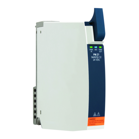
Anhang B Anhang B 15.1 Geräteaufbau Gerätelement Beschreibung Sicherungs- Sicherungsschrauben schrauben für mechanischen Steckverbinder Sicherungs- Torx T20 zum schraube Befestigen am Sockel Hilfsenergie Mechanische Anschluss- Steckverbinder mit kontakte X1 Sicherungsschrauben und Aderleitungen LEDs LEDs zur Status- bzw. Fehleranzeige des Power Moduls 20020E00 Beschriftung Angaben zum Modul... -
Page 22: 15.2 Maßangaben / Befestigungsmaße
Anhang B 15.2 Maßangaben / Befestigungsmaße Maßzeichnungen (alle Maße in mm [Zoll]) – Änderungen vorbehalten 170 [6,69] 155 [6,10] 19757E00 Power Modul 9445/32 18 [7, 66 6,54 67 6,57 19756E00 Power Modul 9445/32 mit Sockel 9496/32-03 Power Modul für Zone 1 279966 / 944560310110 Reihe 9445/32 2022-03-09·BA00·III·de·00... - Page 23 Anhang B Maßzeichnungen (alle Maße in mm [Zoll]) – Änderungen vorbehalten 21456E00 Power Modul 9445/32 mit Sockel 9496/32-04 279966 / 944560310110 Power Modul für Zone 1 2022-03-09·BA00·III·de·00 Reihe 9445/32...
- Page 25 Operating instructions Additional languages r-stahl.com Power module for Zone 1 Series 9445/32...
- Page 26 Contents Contents General Information .....................3 Manufacturer......................3 About these Operating Instructions..............3 Further Documents ....................3 Conformity with Standards and Regulations............3 Explanation of Symbols ..................4 Symbols used in these Operating Instructions.............4 Symbols on the Device ..................4 Safety........................5 Intended Use......................5 Personnel Qualification ..................5 Residual Risks .....................6 Transport and Storage ..................8 Product Selection and Project Engineering ............8 X1 Auxiliary Power Connection................9...
-
Page 27: General Information
Make the operating instructions accessible to operating and maintenance staff at all times. ▶ Pass the operating instructions on to each subsequent owner or user of the device. ▶ Update the operating instructions every time R. STAHL issues an amendment. ID no.: 279966 / 944560310110 Publication code: 2022-03-09·BA00·III·en·00... -
Page 28: Explanation Of Symbols
Explanation of Symbols Explanation of Symbols Symbols used in these Operating Instructions Symbol Meaning Handy hint for making work easier Dangerous situation which can result in fatal or severe injuries DANGER! causing permanent damage if the safety measures are not complied with. -
Page 29: Se Fi
Specialists who perform these activities must have a level of knowledge that meets applicable national standards and regulations. Additional knowledge is required for any activity in hazardous areas! R. STAHL recommends having a level of knowledge equal to that described in the following standards: •... -
Page 30: Residual Risks
▶ Do not place any loads on the device. ▶ Check the packaging and the device for damage. Report any damage to R. STAHL immediately. Do not commission a damaged device. ▶ Store the device in its original packaging in a dry place (with no condensation), and make sure that it is stable and protected against the effects of vibrations and knocks. - Page 31 Only connect compatible components (IS1+/IS1 Remote I/O system). If in doubt, consult R. STAHL. ▶ Repair work on the device must be performed only by R. STAHL. ▶ Gently clean the device with a damp cloth only – do not use scratching, abrasive or aggressive cleaning agents or solutions.
-
Page 32: Gr 4 Transport And Storage
Transport and Storage 3.3.2 Damage to electrical Components Sensitive electronic components can be damaged by electrostatic discharge (ESD). ▶ Before making contact with the device, discharge the charge to a grounded metal body. ▶ Avoid direct contact with connectors or the contacts on the module slots. ▶... -
Page 33: X1 Auxiliary Power Connection
Product Selection and Project Engineering Project engineering specifications depending on the ambient temperature Adjust mounting processes based on the maximum ambient temperature, see the "Technical data" chapter. Updating/replacing modules Observe chapter 6.2. X1 Auxiliary Power Connection To connect the auxiliary power using a 24 V auxiliary power set (item no. 261232 or 272278), see chapter 6.3. -
Page 34: 6 Mounting And Installation
Mounting and Installation Mounting and Installation DANGER! Explosion hazard due to incorrect mounting! Non-compliance results in severe or fatal injuries! ▶ Only mount the device on clean contact surfaces. ▶ Fit the device using safety screws. ▶ Tighten the safety screws using a tightening torque of 1.5 to 1.9 Nm. Mounting/Dismounting ▶... -
Page 35: Replacing And Upgrading The Module
Mounting and Installation Replacing and Upgrading the Module 6.2.1 Replacing the 9445/32 Power Module ▶ Switch off the power supply to the IS1+ Remote I/O System. ▶ Loosen the safety screw on the blue auxiliary power plug and detach the plug with single cores, see chapter 6.3.1. -
Page 36: Installation
Mounting and Installation 6.2.3 Upgrading the 9441/12 IS1 Ethernet CPU Series to 9442/32 IS1+ CPU ▶ Switch off the power supply to the IS1 Remote I/O station. ▶ Disconnect the connection lines for communication (FO) (see 9441/12 operating instructions). ▶ Dismount the 9441/12 IS1 Ethernet CPU, 9444/12 power module and 9492 socket (see operating instructions for 9441/12 CPU, 9444 power module and 9492 socket). -
Page 37: 7 Parameterisation And Commissioning
Parameterisation and Commissioning ▶ Connect the connection line in accordance with the following table: Variant Item no. Core colour Connection 261232 dark blue "+24 V" supply voltage dark blue/white "GND" supply voltage 272278 violet "+24 V" supply voltage dark blue "GND"... -
Page 38: Troubleshooting
Operation Troubleshooting Error notifications can be read out using the IS1+ detect tool. Status or error indication for the power module LED status Status Cause of error Troubleshooting "PWR IN" LED Operation No error – (green) lights up indication "PWR IN" LED No function •... - Page 39 LED lights up at the same time) If the error cannot be eliminated using the specified procedures: ▶ Contact R. STAHL Schaltgeräte GmbH. For rapid processing, have the following information ready: • Type and serial number of the device • DCS/PLC •...
-
Page 40: Ee 9 Maintenance, Overhaul, Repair
Returning the Device ▶ Only return or package the devices after consulting R. STAHL! Contact the responsible representative from R. STAHL. R. STAHL's customer service is available to handle returns if repair or service is required. ▶ Contact customer service personally. ▶... -
Page 41: Cleaning
NOTICE! Malfunction or damage to the device due to the use of non-original components. Non-compliance can result in material damage. ▶ Use only original accessories and spare parts from R. STAHL Schaltgeräte GmbH (see data sheet). 279966 / 944560310110 Power module for Zone 1 2022-03-09·BA00·III·en·00... - Page 42 Appendix A Appendix A 14.1 Technical Data Explosion protection Global (IECEx) IECEx PTB 17.0042X Ex eb mb [ia Ga] [ib Gb] IIC T4 Gb Europe (ATEX) PTB 17 ATEX 2026 X E II 2 (1) (2) G Ex eb mb [ia Ga] [ib Gb] IIC T4 Gb Certificates and approvals Certifications IECEx, ATEX...
-
Page 43: Technical Data
Appendix A Technical data Galvanic separation Test voltage according to EN 60079-11 standard Between the 1500 V AC auxiliary power and BusRail/ CPU/socket Electromagnetic Tested to the following standards and regulations: compatibility EN 61326-1 (2013), IEC 61000-4-1 to 61000-4-6, NAMUR NE 21 Electrical connection Auxiliary power 2-pole via a pluggable terminal with a 3 m single core;... - Page 44 Only connect the 9445/32 power module to the 9496/32 socket Mounting orientation horizontal or vertical (Observe the 9496/32 socket operating instructions) Screw versions Torx 20 For further technical data, see r-stahl.com. Power module for Zone 1 279966 / 944560310110 Series 9445/32 2022-03-09·BA00·III·en·00...
-
Page 45: 15.1 Device Design
Appendix B Appendix B 15.1 Device Design Device element Description Safety screws Safety screws for mechanical plug connectors Safety screw Torx T20 for mounting on the socket X1 connector Mechanical plug contacts connector with safety auxiliary power screws and single cores LEDs LEDs for status or error indication for the... -
Page 46: 15.2 Dimensions/Fastening Dimensions
Appendix B 15.2 Dimensions/Fastening Dimensions Dimensional drawings (all dimensions in mm [inch]) – Subject to change 170 [6,69] 155 [6,10] 19757E00 9445/32 power module 18 [7, 66 6,54 67 6,57 19756E00 9445/32 power module with 9496/32-03 socket Power module for Zone 1 279966 / 944560310110 Series 9445/32 2022-03-09·BA00·III·en·00... - Page 47 Appendix B Dimensional drawings (all dimensions in mm [inch]) – Subject to change 21456E00 9445/32 power module with 9496/32-04 socket 279966 / 944560310110 Power module for Zone 1 2022-03-09·BA00·III·en·00 Series 9445/32...
Need help?
Do you have a question about the 9445 Series and is the answer not in the manual?
Questions and answers