Chapters
Table of Contents

Related Manuals for Stahl 9472/35 Series


Summary of Contents for Stahl 9472/35 Series
- Page 1 Betriebsanleitung Additional languages r-stahl.com Digital Input Output Modul 24 V für Zone 2 Ex n Reihe 9472/35...
-
Page 2: Table Of Contents
Inhaltsverzeichnis Allgemeine Angaben ...................3 Hersteller ......................3 Angaben zur Betriebsanleitung ................3 Weitere Dokumente ....................3 Konformität zu Normen und Bestimmungen ............3 Erläuterung der Symbole ..................3 Symbole in der Betriebsanleitung ...............3 Warnhinweise .....................4 Symbole am Gerät ....................4 Sicherheitshinweise ....................5 Aufbewahrung der Betriebsanleitung ..............5 Qualifikation des Personals ................5 Sichere Verwendung ...................5 Umbauten und Änderungen ................6... -
Page 3: De De
Die Originalbetriebsanleitung ist die englische Ausgabe. Diese ist rechtsverbindlich in allen juristischen Angelegenheiten. Weitere Dokumente • Kopplungsbeschreibung IS1+ (Download unter r-stahl.com) • Anleitung "Erdung und Schirmung" (Download unter r-stahl.com) • Datenblatt • FMEDA Report SIL Dokumente in weiteren Sprachen, siehe r-stahl.com. -
Page 4: 2.2 Warnhinweise
Erläuterung der Symbole Warnhinweise Warnhinweise unbedingt befolgen, um das konstruktive und durch den Betrieb bedingte Risiko zu minimieren. Die Warnhinweise sind wie folgt aufgebaut: • Signalwort: GEFAHR, WARNUNG, VORSICHT, HINWEIS • Art und Quelle der Gefahr/des Schadens • Folgen der Gefahr •... -
Page 5: Sicherheitshinweise
Normen und Bestimmungen umfasst. Für Tätigkeiten in explosionsgefährdeten Bereichen sind weitere Kenntnisse erforderlich! R. STAHL empfiehlt einen Kenntnisstand, der in folgenden Normen beschrieben wird: • IEC/EN 60079-14 (Projektierung, Auswahl und Errichtung elektrischer Anlagen) • IEC/EN 60079-17 (Prüfung und Instandhaltung elektrischer Anlagen) •... -
Page 6: Umbauten Und Änderungen
Sicherheitshinweise • Beigelegtes Warnschild "Warning: Do not separate terminals when energized unless location is known to be non hazardous" ("Warnung: Klemmen erst dann vom Modul trennen, sobald sichergestellt ist, dass die Betriebsumgebung nicht explosionsgefährdet (sicherer Bereich) ist.") in der Nähe der Klemmen anbringen. •... -
Page 7: Funktion Und Geräteaufbau
Funktion und Geräteaufbau Funktion und Geräteaufbau GEFAHR Explosionsgefahr durch zweckentfremdete Verwendung! Nichtbeachten führt zu schweren oder tödlichen Verletzungen. • Gerät nur entsprechend den in dieser Betriebsanleitung festgelegten Betriebsbedingungen verwenden. • Gerät nur entsprechend dem in dieser Betriebsanleitung genannten Einsatzzweck verwenden. Funktion Einsatzbereich Das Digital Input Output Modul 24 V Typ 9472/35 ist –... -
Page 8: Geräteaufbau
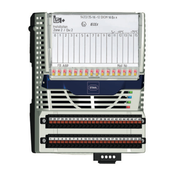
Funktion und Geräteaufbau Geräteaufbau Gerätelement Beschreibung Abdeckung Abdeckung mit Einlegeschild und Anschlussplan (geöffnet) Beschriftung Angaben zum Modul (Seriennummer, Hardware- Revisionsnummer, Software- Revisionsnummer, Herstelldatum, z.B.: 12345678914-004 Rev.A 01-01 0516) LEDs (rot) zur Fehleranzeige (Drahtbruch/Kurzschluss) je Kanal. LEDs (gelb) zur Statusanzeige (AN/AUS) je Kanal. -
Page 9: Technische Daten
Technische Daten Technische Daten Explosionsschutz Global (IECEx) IECEx DEK 16.0010X Ex ec ic [ia Ga] IIC T4 Gc oder Ex nA ic [ia Ga] IIC T4 Gc Europa (ATEX) DEKRA 16 ATEX 0016 X E II 3 (1) G Ex ec ic [ia Ga] IIC T4 Gc oder E II 3 (1) G Ex nA ic [ia Ga] IIC T4 Gc Bescheinigungen und Zertifikate... - Page 10 Technische Daten Technische Daten Frequenzeingang und Zählereingang Max. Anzahl 8 (Kanal 8 ... 15) Kanäle Max. NAMUR-Signal: 20 kHz Schaltfrequenz (bei Frequenzen > 1 kHz verringert sich die maximale Leitungslänge, z.B. bei 5 kHz auf ca. 75 m) 3-Leiter- ( 300 Hz (20 kHz nur mit push-pull Geber) PNP-Initiator / Die Eingänge müssen nach +24 V und nach 0 V geschaltet werden.
- Page 11 Technische Daten Technische Daten Ausgänge Max. Anzahl 16 (Kanal 0 ... 15) Kanäle Externe für 3-Leiter-PNP-Initiatoren, aktive 24 V Signale und digitale Ausgänge Versorgung X0 Externe 18 ... 32 V DC (max. zulässige Spannung U = 32 V DC) Versorgungs- spannung U Max.
- Page 12 Technische Daten Technische Daten Steuereingang X0 "Anlagen-AUS" Funktion "Anlagen-AUS" zum Abschalten aller Ausgänge Eignung Abschaltung bis SIL 2, low demand (IEC 61058) Steuereingang Klemmen X0.3; X0.4 Ausgangsspannung ohne Last 9,7 ... 14,0 V (bei ext. Versorgung 18 ... 32 V) Kurzschlussstrom 0,36 ...
- Page 13 Technische Daten Technische Daten Externe Versorgung Steckbare, schwarze Klemmen, 4-polig, und "Anlagen-AUS" Schraubklemmen Ausführung mit Arretierung (enthalten) Anschluss einadrig - starr 0,2 ... 1,5 mm (AWG 28 ... 14) - flexibel mit Aderendhülsen 0,25 ... 1,5 mm (ohne Kunststoffhülse) - flexibel mit Aderendhülsen 0,25 ...
- Page 14 Technische Daten Technische Daten Gerätespezifische Daten Einstellungen Modul Diagnose-Meldung EIN / AUS Signal Signal-Typ NAMUR-Initiator / Kontakt (Default); 3-Leiter-PNP-Initiatoren mit externer Speisung; Ausgang Impuls- 0 s / aus; 0,6 s / klein; 1,2 s / mittel; 2,4 s / groß *) verlängerung / Frequenzfilter Invertieren...
- Page 15 R < 25 Ω im AUS-Zustand Montage / Installation Einbaulage waagrecht oder senkrecht (Betriebsanleitung beachten) Montageart auf 35-mm-DIN-Schiene NS 35/15 (DIN EN 60715) Weitere technische Daten, siehe r-stahl.com. 230244 / 947260310010 Digital Input Output Modul 24 V 2019-03-08·BA00·III·de·01 für Zone 2 Ex n Reihe 9472/35...
-
Page 16: Projektierung
Projektierung Projektierung HINWEIS Ausfall der installierten Geräte im Schaltschrank durch zu hohe Umgebungstemperatur! Nichtbeachten kann zu Sachschäden führen. • Schaltschrank so aufbauen und einrichten, dass er immer innerhalb des zulässigen Temperaturbereichs betrieben wird. Bei der Projektierung folgende Bedingungen beachten: • Installation des Geräts zur bestimmungsgemäßen Verwendung nur auf der IS1 BusRail 9494. -
Page 17: Anschlussbelegung Steckbare Klemmen X1 Und X2
Projektierung Anschlussbelegung steckbare Klemmen X1 und X2 Für das Modul sind steckbare Klemmen X1 und X2 (Federkraftklemme 245090 und 245091) zum Anschluss von Feldgeräten als Zubehör erhältlich (nicht im Lieferumfang des Moduls enthalten). Die steckbaren Klemmen X1 und X2 haben je 24 Klemmstellen zum Anschluss der Feldkabel. -
Page 18: Anschlussplan Aktive 24 V Signale
Projektierung Anschlussplan aktive 24 V Signale 26 27 28 29 30 31 32 33 34 35 36 37 38 39 40 41 42 43 44 45 46 47 48 3 4 5 6 7 8 9 10 11 12 13 14 15 16 17 18 19 20 21 22 23 24 +24 V 7 ... -
Page 19: Leitungsfehlerunterdrückung
Transport und Lagerung Frequenzeingänge oder Zähler mit Schaltfrequenzen bis 20 kHz sind nur mit push-pull Geber möglich! Die Eingänge müssen nach + 24 V und nach 0 V geschaltet werden. 26 27 28 29 30 31 32 33 34 3 4 5 6 7 8 9 +24 V 20336E00 Leitungsfehlerunterdrückung... -
Page 20: Montage Und Installation
Montage und Installation Montage und Installation Das Gerät ist für den Einsatz in gasexplosionsgefährdeten Bereichen der Zone 2, in staubexplosionsgefährdeten Bereichen der Zone 22 sowie auch im sicheren Bereich zugelassen. Störfrequenzen im Bereich der Frequenzmessbereiche können die Frequenz / Zählerfunktion stören. Wenn in der Anlage starke elektromagnetische Störquellen vorhanden sind oder die Leitungen länger als 30 m sind, wird empfohlen, geschirmte Feldkabel zu verwenden, um die spezifizierte Genauigkeit zu erreichen. -
Page 21: Montage / Demontage, Gebrauchslage
Montage und Installation Montage / Demontage, Gebrauchslage 8.2.1 Montage / Demontage HINWEIS Fehlfunktion oder Geräteschaden durch unsachgemäße Montage. Nichtbeachten kann Sachschaden verursachen! • Gerät nur in vertikaler oder horizontaler Lage montieren und betreiben! (Orientierung horizontal: Lese-Richtung von unten) Montage auf BusRail •... - Page 22 Montage und Installation 8.2.2 Montage der IP30-Abdeckung Die beiliegende IP30-Abdeckung muss am Modulgehäuse montiert werden. Dabei kann sie vor oder nach der Installation angebracht werden. Bitte beachten: Eine montierte Abdeckung lässt sich später nicht mehr demontieren! • Klemme X0 stecken und mit Sicherungsschrauben sichern.
- Page 23 Montage und Installation • Steckbare Klemmen X0, X1 und X2 auf Modul stecken und mit Schrauben gegen Lockern sichern (Anzugsdrehmoment 0,5 ... 0,6 Nm). • IP30-Abdeckung auf X0 anbringen (siehe oben). Austausch von Modulen Beim Austausch des Moduls durch ein baugleiches Modul werden die eingestellten Parameter übernommen.
-
Page 24: 8.3 Installation
Inbetriebnahme Installation Bei Betrieb unter erschwerten Bedingungen wie insbesondere auf Schiffen sind zusätzliche Maßnahmen zur korrekten Installation je nach Einsatzort zu treffen. Weitere Informationen und Anweisungen hierzu erhalten Sie gerne auf Anfrage von Ihrem zuständigen Vertriebskontakt. In der Abdeckklappe befindet sich ein Einlegeschild, in das die Zuordnung der Feldgeräte zu den Kanälen eingetragen werden kann. -
Page 25: Betrieb
Betrieb Betrieb 10.1 Anzeigen Entsprechende LEDs am Gerät zeigen den Betriebszustand des Geräts an (siehe auch Kapitel "Funktion und Geräteaufbau"). Farbe Bedeutung LED "RUN" grün Betriebsanzeige LED "ERR" Anzeige Modulfehler LED "M/S" blau Wartungsbedarf oder Umgebungstemperatur zu hoch LED "24 V" grün/ grün: 24 V vorhanden (18 ... - Page 26 "Leitungsbruch bei deaktiviertem Prüfstrom" ist nur bei eingeschaltetem Ausgang erkennbar. Wenn sich der Fehler mit den genannten Vorgehensweisen nicht beheben lässt: • An R. STAHL Schaltgeräte GmbH wenden. Zur schnellen Bearbeitung folgende Angaben bereithalten: • Typ und Seriennummer des Geräts • DCS/SPS •...
-
Page 27: Instandhaltung, Wartung, Reparatur
GEFAHR Explosionsgefahr durch unsachgemäße Reparatur! Nichtbeachten führt zu schweren oder tödlichen Verletzungen. • Reparaturen an den Geräten ausschließlich durch R. STAHL Schaltgeräte GmbH ausführen lassen. 230244 / 947260310010 Digital Input Output Modul 24 V 2019-03-08·BA00·III·de·01 für Zone 2 Ex n... -
Page 28: Rücksendung
Reinigung 11.4 Rücksendung • Rücksendung bzw. Verpackung der Geräte nur in Absprache mit R. STAHL durchführen! Dazu mit der zuständigen Vertretung von R. STAHL Kontakt aufnehmen. Für die Rücksendung im Reparatur- bzw. Servicefall steht der Kundenservice von R. STAHL zur Verfügung. - Page 29 Operating instructions Additional languages r-stahl.com Digital Input Output Module 24 V for Ex n Zone 2 Series 9472/35...
- Page 30 Contents General Information ....................3 Manufacturer .......................3 Information regarding the Operating Instructions ..........3 Further Documents .....................3 Conformity with Standards and Regulations ............3 Explanation of the Symbols ................3 Symbols in these Operating Instructions ............3 Warning Notes ....................4 Symbols on the Device ..................4 Safety Notes .......................5 Operating Instructions Storage ................5 Personnel Qualification ..................5...
-
Page 31: En En
The original instructions are the English edition. They are legally binding in all legal affairs. Further Documents • IS1+ coupling description (download from r-stahl.com) • "Earthing and shielding" instructions (download from r-stahl.com) • Data sheet • FMEDA Report SIL For documents in additional languages, see r-stahl.com. -
Page 32: 2.2 Warning Notes
Explanation of the Symbols Warning Notes Warnings must be observed under all circumstances, in order to minimize the risk due to construction and operation. The warning notes have the following structure: • Signalling word: DANGER, WARNING, CAUTION, NOTICE • Type and source of danger/damage •... -
Page 33: Safety Notes
• Use the device in accordance with its intended and approved purpose only. • Always consult with R. STAHL Schaltgeräte GmbH if using the device under operating conditions which are not covered by the technical data. • Before installation, make sure that the device is not damaged. -
Page 34: Modifications And Alterations
Safety Notes • Attach the warning sign supplied: "Warning: Do not separate terminals when energized unless location is known to be non hazardous" near to the terminals. • It is only permissible to insert or remove pluggable terminals for non-intrinsically safe electrical circuits when these are de-energised or if it can be guaranteed that an explosive atmosphere is not present (hot work permit, gas warning device or in the case of installation in a non-Ex area). -
Page 35: Function And Device Design
Function and Device Design Function and Device Design DANGER Explosion hazard due to improper use! Non-compliance results in severe or fatal injuries. • Use the device only in accordance with the operating conditions described in these operating instructions. • Use the device only for the intended purpose specified in these operating instructions. -
Page 36: 4.2 Device Design
Function and Device Design Device Design Device component Description Covering Covering with insert disc and connection diagram (open) Labelling Module data (Serial number, hardware revision number, software revision number, date of manufacture, e.g.: 12345678914-004 Rev.A 01-01 0516) LEDs (red) for error indication (wire breakage/short circuit) for each channel. -
Page 37: Technical Data
Technical Data Technical Data Explosion Protection Global (IECEx) IECEx DEK 16.0010X Ex ec ic [ia Ga] IIC T4 Gc Ex nA ic [ia Ga] IIC T4 Gc Europe (ATEX) DEKRA 16 ATEX 0016 X E II 3 (1) G Ex ec ic [ia Ga] IIC T4 Gc E II 3 (1) G Ex nA ic [ia Ga] IIC T4 Gc Certifications and certificates Certificates... - Page 38 Technical Data Technical Data Frequency and counter inputs Max. number of 8 (channel 8 to 15) channels Max. switching NAMUR signal: 20 kHz frequency (at frequencies > 1 kHz the maximum conductor length is reduced, e.g. at 5 kHz to approx. 75 m) 3-conductor PNP ( 300 Hz (20 kHz only with push-pull transmitter) proximity switch /...
- Page 39 Technical Data Technical Data Outputs Max. number of 16 (channel 0 to 15) channels X0 external supply For 3-conductor PNP proximity switches, active 24 V signals and digital outputs External supply 18 to 32 V DC (max. permissible voltage U = 32 V DC) voltage U Max.
- Page 40 Technical Data Technical Data X0 "Plant STOP" control input Function "Plant STOP" to switch off all outputs Suitability Disconnection up to SIL 2, low demand (IEC 61508) Control input Terminals X0.3; X0.4 Output voltage without load 9.7 to 14.0 V (for 18 to 32 V external power supply) Short-circuit current...
- Page 41 Technical Data Technical Data External supply and Pluggable, black terminals, 4-pin, "Plant OFF" X0 screw terminal version with lock (included) Single-wire connection - rigid 0,2 to 1,5 mm (AWG 28 to 14) - flexible with core end sleeves 0,25 to 1,5 mm (without plastic sleeve) - flexible with core end sleeves 0,25 to 1,5 mm...
- Page 42 Technical Data Technical Data Device-specific data Settings Module Diagnostics ON / OFF message Signal Signal type NAMUR proximity switch / contact (default); 3-conductor PNP proximity switches with external supply; output Pulse extension / 0 s / off; 0.6 s / small; 1.2 s / medium; 2.4 s / large *) frequency filter Inverting input/ normal / inverted*)
- Page 43 Installation position Horizontal or vertical (observe operating instructions) Mounting type on 35 mm DIN rail NS 35/15 (DIN EN 60715) For further technical data, see r-stahl.com. 230244 / 947260310010 Digital Input Output Module 24 V 2019-03-08·BA00·III·en·01 for Ex n Zone 2...
-
Page 44: Engineering
Engineering Engineering NOTICE An ambient temperature that is too high may cause failure of the devices installed in the cabinet. Non-compliance can result in material damage. • Install and adjust the cabinet in such a way that it is always operated within the permissible temperature range. -
Page 45: Terminal Assignment Of The Pluggable Terminals X1 And X2
Engineering Terminal Assignment of the pluggable Terminals X1 and X2 For the module, two pluggable terminals X1 and X2 (spring clamp terminals 245090 and 245091) for connection of field devices are available as accessories (not included in delivery of the module). The pluggable terminals X1 and X2 have 24 clamping units for connection of the field cables. -
Page 46: Connection Diagram, Active 24 V Signals
Engineering Connection Diagram, active 24 V Signals 26 27 28 29 30 31 32 33 34 35 36 37 38 39 40 41 42 43 44 45 46 47 48 3 4 5 6 7 8 9 10 11 12 13 14 15 16 17 18 19 20 21 22 23 24 +24 V 7 ... -
Page 47: Line Fault Suppression
Transport and Storage Frequency inputs of counters with switching frequencies up to 20 kHz are possible only with push-pull transmitters! The inputs must be switched to +24 V and 0 V. 26 27 28 29 30 31 32 33 34 3 4 5 6 7 8 9 +24 V 20336E00... -
Page 48: Mounting And Installation
Mounting and Installation Mounting and Installation The device is approved for use in gas explosion hazardous areas of Zone 2 and dust explosion hazardous area of Zone 22 and in safe areas. Interfering frequencies in the frequency measuring ranges can interfere with the frequency/counter function. -
Page 49: Mounting / Dismounting, Operating Position
Mounting and Installation Mounting / Dismounting, Operating Position 8.2.1 Mounting / Dismounting NOTICE Malfunction or device damage caused by improper mounting. Non-compliance may lead to material damage! • Only install and operate the device in a vertical or horizontal position! (Horizontal orientation: Reading direction from below) Mounting on BusRail •... - Page 50 Mounting and Installation 8.2.2 Mounting the IP30 Cover The supplied IP30 cover must be mounted on the module enclosure. It can be attached before or after installation. Please note: Once the cover has been mounted, it cannot be removed at a later time. •...
- Page 51 Mounting and Installation • Plug the pluggable terminals X0, X1 and X2 into the module and secure them against loosening using screws (tightening torque 0.5 to 0.6 Nm). • Attach the IP30 cover to X0 (see above). Replacing modules When replacing the module with a module with identical design, the set parameters are maintained.
-
Page 52: 8.3 Installation
Commissioning Installation Operation under difficult conditions, such as, in particular, on ships, requires additional measures to be taken for correct installation, depending on the place of use. Further information and instructions on this can be obtained from your regional sales contact on request. The cover flap features an insert disc which can be used to enter the assignment of the field devices to the channels. -
Page 53: Operation
Operation Operation 10.1 Indications The corresponding LEDs on the device indicate the operating state of the device (see also the chapter "Function and device design"). Colour Meaning "RUN" LED green Operation indication "ERR" LED Module error indication "M/S" LED blue Maintenance required or ambient temperature too high "24 V"... - Page 54 If the error cannot be eliminated using the specified procedures: • Contact R. STAHL Schaltgeräte GmbH. For rapid processing, have the following information ready: • Type and serial number of the device •...
-
Page 55: Maintenance, Overhaul, Repair
DANGER Explosion hazard due to improper repair! Non-compliance results in severe or fatal injuries. • Repair work on the devices must be performed only by R. STAHL Schaltgeräte GmbH. 230244 / 947260310010 Digital Input Output Module 24 V 2019-03-08·BA00·III·en·01 for Ex n Zone 2... -
Page 56: Returning The Device
• Only return or package the devices after consulting R. STAHL! Contact the responsible representative from R. STAHL. R. STAHL's customer service is available to handle returns if repair or service is required. • Contact customer service personally. • Go to the r-stahl.com website. - Page 58 National Electrical Code, ANSI/NFPA 70 Article 500 or Canadian Electrical Code, CSA C22. Installation with the use of an appropriate fieldbus isolator for nonincendive fieldbus circuits (e.g. R. STAHL type 9185). The Ethernet interface is achieved with the use of media converters and switches providing optical Ethernet.
- Page 59 Block Diagram of an RS485 Field Station: I.S. Inputs and Outputs Class I, II, III, DIV 1, Groups A-G; Class I, Zone 0, IIC/IIB or Non I.S. or Nonincendive circuits, Class I, II, III, DIV 2, Group A-G; Class I, Zone 2, Group IIC/IIB Block Diagram of an Ethernet Field Station: I.S.
- Page 60 Examples for System Topology interfacing The IS1+ Remote I/O System is a DIN rail mounted system designed Automation control systems with DIV 2 / Zone 2 to record and output process control signals between hazardous installation of IS1+ Remote I/O System: location transducers and sensors and a nonhazardous location automation system.
- Page 61 2018 08.03. Bagusch IS1+ Remote I/O System Kaiser for CL I, DIV 2 / Zone 2 2 of 2 Overview 9400 6 031 006 1...
- Page 62 Nonhazardous (Unclassified), The Digital Input Output Module Type 9472/35-16-12 is designed to Class I, II, III, Division 2, Group A-D receive up to 16 discrete input signals from dry contacts and NAMUR or Class I, Zone 2, Group IIC/IIB proximity sensors etc. and transfer them to the IS1 CPU & Power Hazardous (Classified) Locations Module.
Need help?
Do you have a question about the 9472/35 Series and is the answer not in the manual?
Questions and answers