
Subscribe to Our Youtube Channel
Related Manuals for Stahl 9470/33


Summary of Contents for Stahl 9470/33
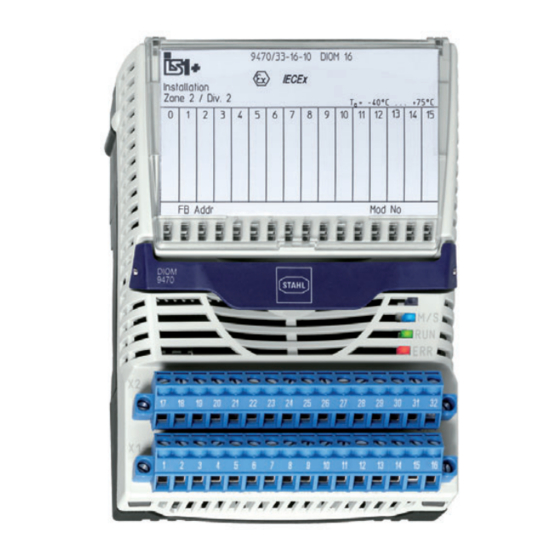
- Page 1 Betriebsanleitung/Operating Instructions Digital Input Output Modul für Zone 2 Digital Input Output Module for Zone 2 > 9470/33...
- Page 3 Betriebsanleitung Digital Input Output Modul für Zone 2 > 9470/33...
-
Page 4: Table Of Contents
Maßangaben / Befestigungsmaße ..............11 Einbaubedingungen ....................11 Montage und Gebrauchslage ................11 LED-Anzeigen und Fehlerbehebung ..............12 Demontage / Modulwechsel ................13 Instandhaltung, Wartung und Störbeseitigung ............14 10.1 Instandhaltung .....................14 10.2 Reparaturhinweise ....................15 Entsorgung ......................15 Zubehör und Ersatzteile ..................15 Digital Input Output Modul für Zone 2 9470/33... -
Page 5: Allgemeine Angaben
2.3 Konformität zu Normen und Bestimmungen Die Konformität zu Normen und Bestimmungen kann den entsprechenden Zertifikaten und der EG-Konformitätserklärung entnommen werden. Diese Dokumente können auf unserer Homepage www.stahl-ex.com abgerufen werden. Verwendete Symbole Sicherheitshinweise Nichtbeachtung kann zu Sachschäden, schweren Verletzungen oder zum Tod führen. -
Page 6: Sicherheitshinweise
Kennwerte und Bemessungsbetriebsbedingungen der Typ- und Datenschilder Zusätzliche Hinweisschilder auf dem Gerät Zusätzliche Sicherheitshinweise: Das Digital Input Output Modul Typ 9470/33 ist für den Einsatz in gas-explosionsgefährdeten Bereichen der Zone 2 und im sicheren Bereich zugelassen. -
Page 7: Umbauten Und Änderungen
162718 oder Federkraftklemmen 162695, 162716) zum Anschluss von Feldgeräten als Zubehör erhältlich (nicht im Lieferumfang des Moduls enthalten!). Die steckbaren Klemmen X1 und X2 haben 16 Klemmen zum Anschluss der Feldkabel. 218130 / 9470613310 Digital Input Output Modul 2015-12-16·BA00·III·de·01 für Zone 2 9470/33... -
Page 8: Technische Daten
Zweiter Kanal (9, 11, 13, 15) = Richtung (0 = vorwärts, 1 = rückwärts) Sensor 1 Sensor 2 ch 1 Richtung vorwärts ch 1 Richtung rückwärts 15340E00 Technische Daten Explosionsschutz Global (IECEx) Gas und Staub IECEx DEK 12.0044X Digital Input Output Modul 218130 / 9470613310 für Zone 2 2015-12-16·BA00·III·de·01 9470/33... - Page 9 Max. Strom I 41,6 mA Max. Leistung P 102 mW Max. innere Kapazität C 10 nF Max. anschließbare Induktivität L /Kapazität C [mH] 0,01 [μF] 0,32 0,41 0,56 0,69 0,88 218130 / 9470613310 Digital Input Output Modul 2015-12-16·BA00·III·de·01 für Zone 2 9470/33...
- Page 10 4 (je zwei Eingänge parallel geschaltet) Funktion Up/Down-Zähler; Frequenz mit Richtung Auflösung 16 Bit / 32 Bit Ausgänge Max. Anzahl Kanäle Anwendung Ex i Low-Power-Magnetventile Leerlaufspannung 8,2 V Digital Input Output Modul 218130 / 9470613310 für Zone 2 2015-12-16·BA00·III·de·01 9470/33...
- Page 11 Arretierung Hilfsenergie Ausführung Eigensicher Ex ia über BusRail Max. Stromaufnahme 120 mA Max. Leistungsaufnahme 2,5 W Max. Verlustleistung 2,5 W Gerätespezifische Daten Einstellungen Modul Diagnose-Meldung EIN / AUS 218130 / 9470613310 Digital Input Output Modul 2015-12-16·BA00·III·de·01 für Zone 2 9470/33...
-
Page 12: Transport Und Lagerung
35-mm-DIN-Schiene NS 35/15 (DIN EN 60715) Transport und Lagerung Transport und Lagerung sind nur in Originalverpackung gestattet. Die Geräte sind trocken und erschütterungsfrei zu lagern. Digital Input Output Modul 218130 / 9470613310 für Zone 2 2015-12-16·BA00·III·de·01 9470/33... -
Page 13: Installation
Montage senkrecht mit steckbaren Klemmen unten, links oder rechts. BusRail BusRail 05683E00 Modul senkrecht auf vorgesehenen Steckplatz der BusRail aufsetzen Modul durch leichtes Drücken einrasten 218130 / 9470613310 Digital Input Output Modul 2015-12-16·BA00·III·de·01 für Zone 2 9470/33... -
Page 14: Led-Anzeigen Und Fehlerbehebung
I/O-Modul vorhanden oder • CPM oder CPU&PM prüfen I/O-Modul defekt. • BusRail prüfen • I/O-Modul richtig auf BusRail aufrasten • I/O-Modul tauschen LED „ERR“, rot Kein Fehler Digital Input Output Modul 218130 / 9470613310 für Zone 2 2015-12-16·BA00·III·de·01 9470/33... -
Page 15: Demontage / Modulwechsel
Modulausfall der Lebensdauer erreicht 9.5 Demontage / Modulwechsel WARNUNG Wenn eine Trennwand montiert ist, müssen als Erstes die Klemmen X1 und X2 vom auszutauschenden Modul abgezogen werden. 218130 / 9470613310 Digital Input Output Modul 2015-12-16·BA00·III·de·01 für Zone 2 9470/33... -
Page 16: Instandhaltung, Wartung Und Störbeseitigung
10 Instandhaltung, Wartung und Störbeseitigung 10.1 Instandhaltung Das Modul benötigt keine regelmäßige Wartung. Beachten Sie die bestimmungsgemäße Funktion Halten Sie sich an die Richtlinien nach IEC/EN 60079-17 Digital Input Output Modul 218130 / 9470613310 für Zone 2 2015-12-16·BA00·III·de·01 9470/33... -
Page 17: Reparaturhinweise
Explosionsgefahr durch falsche oder unzureichende Ersatzteile oder falsches Zubehör! Bei EX-Schutz relevanten Bauteilen nur passende, zertifizierte Ersatzteile bzw. entsprechendes Zubehör der R. STAHL Schaltgeräte GmbH oder anderer Hersteller verwenden. Ansonsten kann der Explosionsschutz nicht mehr gewährleistet sein. - Page 18 Zur Montage zwischen eigensicheren und Trennwand 220101 0,000 nicht-eigensicheren Anschlüssen der I/O-Module, um die 50 mm Fadenmaß einzuhalten 15196E00 Warnschild „Module nur mit feuchtem Tuch säubern“ 162796 0,001 05872E00 Digital Input Output Modul 218130 / 9470613310 für Zone 2 2015-12-16·BA00·III·de·01 9470/33...
- Page 19 Operating instructions Digital Input Output Module for Zone 2 > 9470/33...
- Page 20 Mounting and operating position .................11 LED indications and troubleshooting ..............12 Dismounting / replacement of the module ............13 Maintenance, overhaul and repair ...............14 10.1 Maintenance ......................14 10.2 Repair instructions ....................15 Disposal .......................15 Accessories and spare parts ................15 Digital Input Output Module for Zone 2 9470/33...
-
Page 21: General Information
General information General information 2.1 Manufacturer R. STAHL Schaltgeräte GmbH Am Bahnhof 30 74638 Waldenburg Germany Phone: +49 7942 943-0 Fax: +49 7942 943-4333 Internet: www.stahl-ex.com 2.2 Information regarding the operating instructions ID-No.: 218130 / 9470613310 Publication code: 2015-12-16·BA00·III·en·01 2.3 Conformity with standards and regulations Conformity with standards and regulations is specified in the corresponding certificates and the EC Declaration of Conformity. -
Page 22: Safety Notes
Additional information plates fixed directly to the device Additional safety notes: The digital input output module Type 9470/33 is approved for use in gas hazardous areas of Zone 2 and in the safe area. The digital input output module Type 9470/33 is approved for use in ... -
Page 23: Alterations And Modifications
(not included in the scope of delivery of the module!). The pluggable terminals X1 and X2 have 16 terminals for connection of the field cables. 218130 / 9470613310 Digital Input Output Module 2015-12-16·BA00·III·en·01 for Zone 2 9470/33... -
Page 24: Technical Data
Second channel (9, 11, 13, 15) = direction (0 = forward, 1 = backward) Sensor 1 Sensor 2 ch 1 Direction forwards ch 1 Direction backwards 15340E00 Technical data Explosion protection Global (IECEx) Digital Input Output Module 218130 / 9470613310 for Zone 2 2015-12-16·BA00·III·en·01 9470/33... - Page 25 41,6 mA Max. power P 102 mW Max. internal capacity C 10 nF Max. connectable inductance L /capacity C [mH] 0.01 [μF] 0.32 0.41 0.56 0.69 0.88 218130 / 9470613310 Digital Input Output Module 2015-12-16·BA00·III·en·01 for Zone 2 9470/33...
- Page 26 4 (each two inputs switched in parallel) Function Up/down counter; Frequency with direction Resolution 16 bit / 32 bit Outputs Max. number of channels Application Ex i low-power solenoid valves Open-circuit voltage 8.2 V Digital Input Output Module 218130 / 9470613310 for Zone 2 2015-12-16·BA00·III·en·01 9470/33...
- Page 27 Intrinsically safe Ex ia via BusRail Max. current consumption 120 mA Max. power consumption 2.5 W Max. power dissipation 2.5 W Device-specific data Settings Module Diagnostics message ON / OFF 218130 / 9470613310 Digital Input Output Module 2015-12-16·BA00·III·en·01 for Zone 2 9470/33...
-
Page 28: Transport And Storage
35 mm DIN rail NS 35/15 (DIN EN 60715) Transport and storage Transport and storage are only permitted in the original packaging. The devices must be stored in a dry place and vibration-free. Digital Input Output Module 218130 / 9470613310 for Zone 2 2015-12-16·BA00·III·en·01 9470/33... -
Page 29: Installation
Position the module vertically on the provided slot of the BusRail Snap module into place by slightly pressing it Connecting field devices to the module 218130 / 9470613310 Digital Input Output Module 2015-12-16·BA00·III·en·01 for Zone 2 9470/33... -
Page 30: Led Indications And Troubleshooting
• Check CPM or CPU&PM defective. • Check the BusRail • Engage the I/O module correctly on the BusRail • Replace the I/O module LED "ERR", red No error Digital Input Output Module 218130 / 9470613310 for Zone 2 2015-12-16·BA00·III·en·01 9470/33... -
Page 31: Dismounting / Replacement Of The Module
When replacing the module by a module with a different function, the module reports a configuration error (red LED "ERR" flashes). The module must be either re-parameterised or it is necessary to connect a module of the right type. 218130 / 9470613310 Digital Input Output Module 2015-12-16·BA00·III·en·01 for Zone 2 9470/33... -
Page 32: Maintenance, Overhaul And Repair
If the blue LED "M/S" lights up continuously, it is recommended to replace the module in the foreseeable future. Otherwise there is a high probability that the module will fail in 12 months (see "LED indications and troubleshooting"). Digital Input Output Module 218130 / 9470613310 for Zone 2 2015-12-16·BA00·III·en·01 9470/33... -
Page 33: Repair Instructions
For components with relevant Ex protection, use only suitable, certified spare parts or corresponding accessories of R. STAHL Schaltgeräte GmbH or other manufacturers. Otherwise, explosion protection cannot be guaranteed any longer. R. STAHL Schaltgeräte GmbH cannot be held liable for damage caused by ignoring this danger. Designation Figure Description Art. - Page 34 I/O modules, in order to adhere to the required 50 mm distance 15196E00 Warning sign "Clean modules only with a damp cloth." 162796 0.001 05872E00 Digital Input Output Module 218130 / 9470613310 for Zone 2 2015-12-16·BA00·III·en·01 9470/33...
- Page 36 Approved NAMUR proximity switches, optocouplers, low power valves 12.0 Wiring legend 23.0 0.02 0.01 Connection allocation – Digital Input Output Module Type 9470/33 4 ch. connected parallel 0.32 9.8 V 0.41 41.6 mA 0.56 channel 0...
Need help?
Do you have a question about the 9470/33 and is the answer not in the manual?
Questions and answers