Table of Contents
Advertisement
Quick Links
Advertisement
Table of Contents

Subscribe to Our Youtube Channel
Related Manuals for HIKVISION UD05108B


Summary of Contents for HIKVISION UD05108B
- Page 1 Thermal Bi-spectrum Network Positioning System Quick Start Guide UD05108B...
- Page 2 YOU FOR ANY SPECIAL, CONSEQUENTIAL, INCIDENTAL, OR INDIRECT DAMAGES, INCLUDING, AMONG OTHERS, DAMAGES FOR LOSS OF BUSINESS PROFITS, BUSINESS INTERRUPTION, OR LOSS OF DATA OR DOCUMENTATION, IN CONNECTION WITH THE USE OF THIS PRODUCT, EVEN IF HIKVISION HAS BEEN ADVISED OF THE POSSIBILITY OF SUCH DAMAGES.
- Page 3 Thermal Network Positioning System·Quick Start Guide REGARDING TO THE PRODUCT WITH INTERNET ACCESS, THE USE OF PRODUCT SHALL BE WHOLLY AT YOUR OWN RISKS. HIKVISION SHALL NOT TAKE ANY RESPONSIBILITES FOR ABNORMAL OPERATION, PRIVACY LEAKAGE OR OTHER DAMAGES RESULTING FROM CYBER ATTACK, HACKER ATTACK, VIRUS INSPECTION, OR OTHER INTERNET SECURITY RISKS;...
- Page 4 Thermal Network Positioning System·Quick Start Guide 2006/66/EC (battery directive): This product contains a battery that cannot be disposed of as unsorted municipal waste in the European Union. See the product documentation for specific battery information. The battery is marked with this symbol, which may include lettering to indicate cadmium (Cd), lead (Pb), or mercury (Hg).
- Page 5 Thermal Network Positioning System·Quick Start Guide Cautions Do not drop the device or subject it to physical shock. Wipe the device gently with a clean cloth and a small quantity of ethanol, if necessary. Do not aim the lens at the sun or any other bright light. ...
-
Page 6: Table Of Contents
Thermal Network Positioning System·Quick Start Guide Table of Contents 1 Preparation....................1 2 Appearance Description ................2 2.1 Type I Positioning System Appearance .............. 2 2.2 Type II Positioning System Appearance ............. 3 2.3 Cable Descriptions ....................4 Alarm In/Out Connections ................5 3 Installing the Positioning System ............ -
Page 7: Preparation
Thermal Network Positioning System·Quick Start Guide 1 Preparation Basic Requirement All the electronic operation should be strictly compliance with the electrical safety regulations, fire prevention regulations and other related regulations in your local region. Check the package contents and make sure that the device in the package is ... -
Page 8: Appearance Description
Thermal Network Positioning System·Quick Start Guide 2 Appearance Description There are two kinds of thermal network positioning systems: Type I positioning system, and Type II positioning system. The appearance description of two cameras are shown below. 2.1 Type I Positioning System Appearance Refer to the following figures for Type I thermal positioning system overview and dimensions. -
Page 9: Type Ii Positioning System Appearance
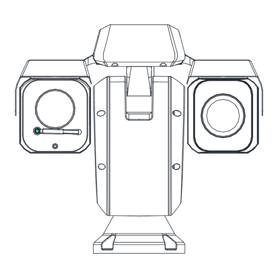
Thermal Network Positioning System·Quick Start Guide 330mm (12.99″) 450mm (17.72″) Figure 2-3 Type I Thermal Positioning System Dimensions (2) 2.2 Type II Positioning System Appearance Refer to the following figures for Type II thermal positioning system overview and dimensions. Figure 2-4 Type II Thermal Positioning System Overview... -
Page 10: Cable Descriptions
Thermal Network Positioning System·Quick Start Guide 351.6mm (13.8″) Figure 2-5 Type II Thermal Positioning System Dimensions (1) 486.1 mm (19.1″) Figure 2-6 Type II Thermal Positioning System Dimensions (2) 2.3 Cable Descriptions The cable interfaces of positioning system are shown in Figure 2-7. The cables of RS-485, power supply, alarm inputs, alarm outputs, etc. -
Page 11: Alarm In/Out Connections
Thermal Network Positioning System·Quick Start Guide Power Cable RS485- RS485+ Video Cable Audio Input / Output Alarm Outputs Alarm Inputs Network Cable Figure 2-7 Cables of Other Positioning Systems 1.1 Alarm In/Out Connections This section is only for the positioning system with alarm in/out functions. The positioning system can be connected with alarm inputs (0~5VDC) and alarm outputs. -
Page 12: Installing The Positioning System
Thermal Network Positioning System·Quick Start Guide 3 Installing the Positioning System 3.1 Monitoring Distance Range Electric lens is adopted for the thermal channel of positioning system. It supports auto-focus function and remote focus function. For different lens focal length, the monitoring range is shown in the table below: Table 3-1 Monitoring Range (Pixel Interval: 17um) Lens Focal Length/mm... -
Page 13: Wiring
Thermal Network Positioning System·Quick Start Guide Lens Focal Length/mm Identification Range (Vehicle)/m Identification Range (Human)/m This table is for reference only, and the actual detection range may vary according to different camera settings, mounting condition, monitor and so When the weather is fine and the atmospheric visibility is normal, the ... -
Page 14: Memory Card Installation
Thermal Network Positioning System·Quick Start Guide Under normal circumstances, the wiring is completed by the professional technicians. However, when the device cannot work normally, you can check the above information to look for reason. 3.3 Memory Card Installation Steps: 1. Open the memory card cover of the right side of the positioning system with cross screwdriver. -
Page 15: Finishing Installing
Thermal Network Positioning System·Quick Start Guide 2. Fix the positioning system onto the bracket base, as shown in Figure 3-3. If no screw thread is found on the screw holes of the bracket base, lock the screw nut. The length of the screws should be 30mm and the diameter of screws should be 8mm. -
Page 16: Setting The System Over The Lan
Thermal Network Positioning System·Quick Start Guide 4 Setting the System over the LAN You shall acknowledge that the use of the product with Internet access might be under network security risks. For avoidance of any network attacks and information leakage, please strengthen your own protection. If the product does not work properly, please contact with your dealer or the nearest service center. -
Page 17: Activation Via Web Browser
Thermal Network Positioning System·Quick Start Guide 4.2.1 Activation via Web Browser Steps: 1. Power on the system, and connect the system to the network. 2. Input the IP address into the address bar of the web browser, and click Enter to enter the activation interface. -
Page 18: Modifying The Ip Address
Thermal Network Positioning System·Quick Start Guide Figure 4-3 SADP Interface 3. Create a password and input the password in the password field, and confirm the password. STRONG PASSWORD RECOMMENDED– We highly recommend you create a strong password of your own choosing (using a minimum of 8 characters, including upper case letters, lower case letters, numbers, and special characters) in order to increase the security of your product. - Page 19 Thermal Network Positioning System·Quick Start Guide Please refer to section 3.2 to activate the system if it is inactive. 3. Change the device IP address to the same subnet with your computer by either modifying the IP address manually or checking the checkbox of Enable DHCP. Figure 4-4 Modify the IP Address 4.
-
Page 20: Operating Via Web Browser
Thermal Network Positioning System·Quick Start Guide 5 Operating via Web browser 5.1 Accessing the System System Requirement: Operating System: Microsoft Windows XP SP1 and above version / Vista / Win7 / Server 2003 / Server 2008 32bits CPU: Intel Pentium IV 3.0 GHz or higher RAM: 1G or higher Display: 1024×... - Page 21 Thermal Network Positioning System·Quick Start Guide Figure 5-1 Login Interface 5. Install the plug-in before viewing the live video and managing the network positioning system. Please follow the installation prompts to install the plug-in. You may have to close the web browser to finish the installation of the plug-in.
-
Page 22: Live View Page
Thermal Network Positioning System·Quick Start Guide 5.2 Live View Page The live video page allows you to view live video, capture images, realize PTZ control, set/call presets and configure video parameters. Menu Bar PTZ Control Show or hide PTZ control panel Live View Window Live View... -
Page 23: Appendix
Thermal Network Positioning System·Quick Start Guide Appendix Frequently Asked Questions (FAQ) Device Running Error Question: The device fails to start up or reboots repeatedly. The device constantly powers off unexpectedly when you pan/tilt the device or call preset. ... - Page 24 Thermal Network Positioning System·Quick Start Guide Question: Live view fails with good network connection. Answer: Examine if the IE plug-in is well installed. Change the Website Blocker settings if necessary. For cross-domain routing, enable the UPnP of device, or set manual mapping to port No.
-
Page 25: Common Material Emissivity Reference
Thermal Network Positioning System·Quick Start Guide Common Material Emissivity Reference Material Temperature (° C/° F) Emissivity Water 0 to 100/32 to 212 0.95~0.98 Soil (Dry) 20/68 0.92 Soil (Moist) 20/68 0.95 Wood 17/62.6 0.962 Sand 20/68 Sandstone 19/66.2 0.909~0.935 PVC (Polyvinyl Chloride) 70/158 0.93 Pitch...
Need help?
Do you have a question about the UD05108B and is the answer not in the manual?
Questions and answers