
Related Manuals for Avigilon 3 Series


Summary of Contents for Avigilon 3 Series
- Page 1 User Guide Avigilon Video Appliance Series 3 Models: VMA-AS3X-8P VMA-AS3-8P VMA-AS3X-16P VMA-AS3-16P VMA-AS3X-24P VMA-AS3-24P...
- Page 2 The use of EMC-compliant support and auxiliary equipment with this device is required in order to fully comply with the EMC regulatory standards. Do not insert anything into the device ventilation openings. Use only accessories recommended by Avigilon. Keep these safety instructions.
- Page 3 This is a Class A product. In a domestic environment this product may cause radio interference in which case the user may be required to take adequate measures. Changes or modifications made to this equipment not expressly approved by Avigilon Corporation or parties authorized by Avigilon Corporation could void the user’s authority to operate this equipment.
- Page 4 This Class B digital apparatus complies with Canadian ICES-003 (B)/NMB-3(B). This equipment satisfies the requirements for use within a residential location. Changes or modifications made to this equipment not expressly approved by Avigilon Corporation or parties authorized by Avigilon Corporation could void the user’s authority to operate this equipment.
- Page 5 Disposal and Recycling Information When this product has reached the end of its useful life, please dispose of it according to your local environmental laws and guidelines. Risk of fire, explosion, and burns. Do not disassemble, crush, heat above 100 °C (212 °F), or incinerate. European Union: This symbol means that according to local laws and regulations your product should be disposed of separately from household waste.
- Page 6 The contents of this document and the specifications of the products discussed herein are subject to change without notice. Avigilon Corporation reserves the right to make any such changes without notice. Neither Avigilon Corporation nor any of its affiliated companies: (1) guarantees the completeness or accuracy of the information contained in this document;...
-
Page 7: Table Of Contents
Connecting to Cameras with Static IP Addresses Configuring the Internal DHCP Server Connecting Additional Video Appliances to a Network Activate the ACC Software and Connect to Avigilon Cloud Services Activate ACC Software and Feature Licenses Connect to Avigilon Cloud Services (Optional) - Page 8 Offline Activation Reactivating a License LED Indicators Front Panel LEDs RJ45 Ethernet LEDs on the Back Panel Connecting to External Devices Adding Local Windows Accounts Restarting the Operating System Resetting the Internal PoE Switch to Factory Defaults Replacing a Hard Drive Enabling the Marvell Storage Utility Checking the Hard Drive Status Replacing a Hard Drive...
-
Page 9: Introduction
Built-in server and storage to run the Avigilon Control Center Server and retain recorded video content. Video ports to display live video and allow users to operate the Avigilon Control Center Client software directly from the appliance. Aggregate throughput of 400 Mbps (on the 16- and 24-port models) and 200 Mbps (on the 8-port model, for simultaneous recording, playback, and live streaming. -
Page 10: Package Contents
Package Contents Ensure the package contains the following: Avigilon Video Appliance Power cord Power supply and screwdriver to secure it (8-port appliance only) Wall installation hardware (8-port appliance only) Rack mounting rails and appliance rack mounting hardware (16- and 24-port appliances) -
Page 11: Before You Start
Before You Start Avigilon recommends the use of an uninterruptible power supply (UPS) system to protect your video surveillance system hardware. A UPS system is used to protect critical equipment from mains supply problems, including spikes, voltage dips, fluctuations and complete power failures using a dedicated battery. -
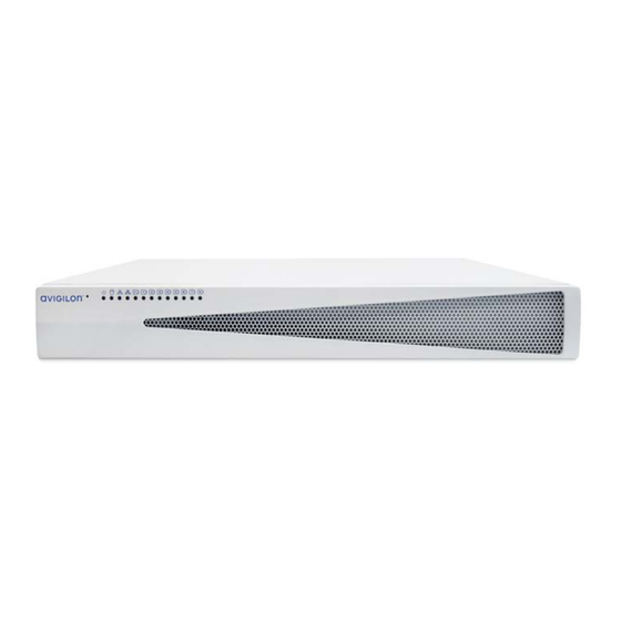
Page 12: Overview
Overview Front View Figure 1: Front view of VMA-AS3-8P / VMA-AS3X-8P, VMA-AS3-16P / VMA-AS3X-16P, and VMA-AS3-24P / VMA-AS3X-24P (top to bottom) 1. Reset button Use this button to reset the internal PoE switch, or restart the operating system of the appliance. For more information, see Resetting the Internal PoE Switch to Factory Defaults on page 43 Restarting the Operating System on... -
Page 13: Rear View
Rear View Figure 2: Rear view of VMA-AS3-8P / VMA-AS3X-8P, VMA-AS3-16P / VMA-AS3X-16P, and VMA-AS3-24P / VMA-AS3X-24P (top to bottom) 1. Digital I/O connector Provides connections to external input/output devices. For more information, see Connecting to External Devices on page 39. 2. - Page 14 component. Can be used to link to other PoE switches and cameras, and to access the web interface of any connected camera video. 6. Local camera connector with PoE Connect cameras to the 10/100 Mbps speed PoE switch component to power the cameras and record video.
-
Page 15: Wall Mounting An 8-Port Video Appliance
Wall Mounting an 8-Port Video Appliance You can mount the 8-port Video Appliance to a wall. This can be useful if you want to install the appliance in a location obscured from view, such as a closet or equipment room, or so that it doesn't take up shelf or counter space. -
Page 16: Installing A Video Appliance In A Rack Unit
Installing a Video Appliance in a Rack Unit To install a 16- or 24-port Video Appliance in a standard EIA-310 19-inch mounting rack, use the matched pair of mounting rails, matched pair of mounting ears, and pair of unit rails provided with the appliance. For more information, see Rack Mounting a 16- or 24-Port Video Appliance on the next page. -
Page 17: Rack Mounting A 16- Or 24-Port Video Appliance
The mounting rails are designed in pairs, with a right and left rail. Each rail is clearly marked to indicate the side of the rack unit it must be attached to, as well as the top and front edges. The rail length is adjustable from 641 mm to 910 mm (25.236"... - Page 18 Figure 6: Mounting the 16P/24P Video Appliance into a rack There is a risk of serious injury and damage to equipment if the Video Appliance falls out of a rack unit. It is extremely important that the Video Appliance is securely fastened to the mounting rails provided with the 16-port or 24-port Video Appliance.
-
Page 19: Rack Mounting An 8-Port Video Appliance
4. Lift the appliance and lower the back of the appliance onto the rails, slide it in against the back bracket of the rails. Slide the unit towards the back of the rack, and ensure the unit rails slide smoothly within the grooves of the mounting rails. - Page 20 Figure 7: Mounting the 8P Video Appliance into a rack There is a risk of serious injury and damage to equipment if the Video Appliance falls out of a rack unit. It is extremely important that the Video Appliance is securely fastened to the rack mount shelf. Refer to the figure above when mounting into a rack.
-
Page 21: Connecting Cables
Connecting Cables Refer to the diagrams in the Overview on page 4 for the location of the different connectors. Make the following connections as required: 1. Connect a KVM switch or separate keyboard, mouse and monitor to the appliance. The keyboard and mouse can be connected to any USB port on the appliance. The monitor can be connected to any HDMI connector at the back of the appliance. -
Page 22: Logging Into Windows 10 For The First Time
6.x.x. This older version of the ACC software will not support newer features such as facial recognition and the Focus of Attention interface. You are logged in to the Windows environment. The Avigilon Control Center Admin Tool and the ACC Client automatically start up. -
Page 23: Video Appliance Network Interface Connections
Video Appliance Network Interface Connections The Video Appliance is a combination of a built-in computer with storage for recorded video content and a network switch that supports IP camera connections. It supports three network interface connections (NICs), two network ports and either 8, 16, or 24 PoE ports (depending on the model). You can see the NICs in the Network Connections window of the operating system, shown in The Network Connections Control Panel showing the three NICs. -
Page 24: Video Appliance Port Connectors
Video Appliance Port Connectors In addition to the PoE port connectors for cameras, the Video Appliance has two network port connectors on the back panel, identified by the following icons: Corporate network uplink port Camera network uplink port Corporate Network Uplink Port Use the corporate network uplink port to connect the computer in the appliance to the corporate network. -
Page 25: Using The Switch Management Webui
Using the Switch Management WebUI The Switch Management WebUI can be accessed using a local web browser directly from the appliance, or from a laptop connected to the camera network uplink port connector if you are using the appliance with its default settings for the WebUI NIC. -
Page 26: Changing Passwords For Switch Management Webui Users
Figure 9: The Switch Management WebUI Log In screen. (Used with permission from Microsoft.) The browser displays a login screen for the Switch Management WebUI. 4. If this is the first time opening the Switch Management WebUI, refer to Changing Passwords for Switch Management WebUI Users below. -
Page 27: Configuring The Poe Budget From The Switch Management Webui
Figure 10: Switch Management WebUI Account | Password tab 4. Change the password for the administrator ID admin. 5. Click Apply. 6. Change the password for the user ID user. 7. Click Apply. 8. Click Logout to exit. 9. When the log in screen reappears, enter the user ID user and the new password. 10. - Page 28 Individual PoE ports can be configured up to a maximum of 36W. This may be useful if you are connecting a device that may occasionally draw more power than the default budget (such as a camera with an IR illuminator or a heater). In that case, you may want to decrease the power budget of other cameras to ensure that when the high-power device draws full power no cameras are dropped for lack of power.
- Page 29 4. Exit the Switch Management WebUI. Configuring the PoE Budget From the Switch Management WebUI...
-
Page 30: Connecting Devices To The Video Appliance
3. A network of connected cameras with previously assigned static IP addresses within a different subnet. This configuration is most likely used by a business that has existing third-party or Avigilon cameras with static IP address that were previously assigned, or if static IP addresses are desired for cameras. -
Page 31: Configuring A Network With An External Dhcp Server
The corporate LAN uplink port is separate from the numbered camera ports, so it will not interfere with video recording. After you connect cameras to the numbered ports, you can configure the Avigilon Control Center system. Activate the ACC Software and Connect to Avigilon Cloud Services on page 33. - Page 32 assign to the appliance. 1. Connect to the appliance: Directly: Connect a keyboard, mouse and monitor to the appliance. From a stand-alone computer, such as a laptop: Configure the laptop in the 192.168.2.0/14 subnet Connect the laptop to the camera network uplink port with an Ethernet cable. 2.
-
Page 33: Configuring The Internal Dhcp Server
4. In the Properties dialog box for the Internal Camera LAN, double-click Internet Protocol Version 4 (TCP/IPv4). Figure 12: The Network Connections window showing the Properties dialog box for the Internal Camera connection. (Used with permission from Microsoft.) 5. In the dialog box that appears, select the Use the following IP address: option and assign the static IP address in the same subnet as the cameras that you obtained. - Page 34 Note: After you setup the internal DHCP server, do not connect any external DHCP servers to the appliance or there may be address conflicts and cause connection issues. Tip: If you are only going to connect Avigilon cameras to the appliance, you do not need to set up a DHCP server. For more information, see Configuring a ZeroConf Device Network on page 22.
- Page 35 The corporate network ports are separate from the numbered camera ports, so they will not interfere with video recording. After you've made the required network and camera connections, you can configure the Avigilon Control Center system. See Activate the ACC Software and Connect to Avigilon Cloud Services on page 33.
-
Page 36: Connecting Additional Video Appliances To A Network
Connecting Additional Video Appliances to a Network Before you can connect an additional Video Appliance to an existing ACC site, you must change the IP addresses of the internal switch and the WebUI port to avoid IP addressing conflicts between the other Video Appliances connected to the same site. - Page 37 1. Connect to the appliance: Directly: Connect a keyboard, mouse and monitor to the appliance. From a stand-alone computer, such as a laptop: Configure the laptop in the same subnet as the internal switch and WebUI port (for example: the 192.168.100.0/24 subnet). Connect the laptop to the camera network uplink port with an Ethernet cable.
- Page 38 Figure 14: Switch Management WebUI IPv4 tab showing the default IP address of the internal switch. d. Change the IP address to a valid unused value in the IP subnet. (For example, if you are using the 192.168.100.0/24 IP subnet, the internal switch on the first appliance could be assigned 192.168.100.11, the second 192.168.100.21, and so on.) e.
- Page 39 c. In the Properties dialog box for the WebUI port, double-click Internet Protocol Version 4 (TCP/IPv4). Figure 15: The Network Connections window showing the Properties dialog box for the WebUI port and its default IP address. (Used with permission from Microsoft.) d.
- Page 40 5. Connect the Video Appliance to a network switch in your corporate network using the corporate network uplink port Connecting Additional Video Appliances to a Network...
-
Page 41: Activate The Acc Software And Connect To Avigilon Cloud Services
You can start to back up the system settings for your new site in the ACC Client software after it is configured. These settings include the ACC password, and the settings for the camera connections. For more information on backing up the site and server configurations, see the Avigilon ACC Client User Guide. Activating a License Once your license is activated, you can immediately use the new licensed features. -
Page 42: Online Activation
Tip: Finish organizing your multi-server site before activating a new license to avoid reactivating the site license each time a new server is added. Online Activation If you have internet access, use online activation. However, if your site is large and contains hundreds of licenses, the server may time out. -
Page 43: Reactivating A License
3. Click Upload. A capabilityResponse.bin file should download automatically. If not, allow the download to occur when you are prompted. 4. Complete the product registration page to receive product updates from Avigilon. 5. Copy the .bin file to a computer running the ACC Client software. - Page 44 d. In the License Management dialog box, click Apply…. e. Select the .bin file and click Open. f. Click OK to confirm your changes. Reactivating a License...
-
Page 45: Led Indicators
LED Indicators The following lists describe what the LEDs on the front and back of each Video Appliance indicate. Front Panel LEDs Icons LED Status Description Green Device is powered and the ACC server is running normally. Orange Device is powered but ACC has been stopped or has crashed and is not running, or device is restarting and the ACC server is not yet running. - Page 46 LED Status Description Orange For PoE ports: On for 100 Mbps speed. Off for 10 Mbps speed. For corporate and camera uplink ports: On for GigE speed. Off for 10/100 Mbps speed. RJ45 Ethernet LEDs on the Back Panel...
-
Page 47: Connecting To External Devices
Connecting to External Devices External devices are connected to the Video Appliance through the digital I/O connector. The pinout for the I/O connector is shown in the following diagram: Figure 16: Digital I/O connector pinout schema. Function Description Alarm Inputs — Active-Low inputs. To activate, connect the Input to the Ground pin (GND). - Page 48 Function Description OUT1 Relay Outputs — Form-A dry contact outputs. When active, terminals are connected. When inactive, terminals are disconnected. OUT2 Note: Contacts are normally open. The contacts are open when the energizing force (magnet or relay solenoid) is not present. When the OUT3 energizing force is present, the contact will close.
-
Page 49: Adding Local Windows Accounts
Adding Local Windows Accounts Not all methods for creating local Windows accounts are supported by the Video Appliance. Use the following method to reliably add local Windows user accounts: 1. Press the Windows key + R on your keyboard to open the Run dialog. 2. -
Page 50: Restarting The Operating System
Use the reset switch while the appliance is powered. An operating system reset does not affect the Ethernet switch component or the connected cameras. The reset switch is located at the front of the appliance and is the small unlabeled hole between the Avigilon logo and the status LED. -
Page 51: Resetting The Internal Poe Switch To Factory Defaults
Windows. Any Windows warning regarding an improper shutdown upon rebooting can be ignored after the reset switch is pressed. The reset switch is located at the front of the appliance and is the small unlabeled hole between the Avigilon logo and the status LED. -
Page 52: Replacing A Hard Drive
Important: Only use a hard drive for the Video Appliance available from your Avigilon dealer. Always replace a hard drive with the same size, make and model, or the appliance will continue to fail. - Page 53 1. Open the Windows system tray and click on the MarvellTray icon: Important: By default, this utility starts when the Video Appliance is powered up and runs in the background. If you don't see the icon in the system tray, you need to start it. From the Windows Start menu, select: 2.
-
Page 54: Replacing A Hard Drive
Physical Disk: port 0 is the hard drive installed on the far left and Physical Disk: port 1 to Physical Disk: port 3 are installed beside each other from left to right. If more than one drive has failed, immediately shut down your system and contact Avigilon Technical Support for possible recovery instructions. -
Page 55: Disabling The Marvell Storage Utility
c. Remove the silver-colored screws on the side that attach the hard drive to the caddy. d. Use some force to push the right-hand side of the hard drive out of the caddy. It is held in place by several pins on the left-hand side. 5. -
Page 56: Replacing The Power Supply In The 16- Or 24-Port Video Appliance
The power supply unit (PSU) in the 16- or 24-port Video Appliance is replaceable if the PSU becomes unreliable or fails. Important: Only use a PSU for the Video Appliance available from your Avigilon dealer. Important: If you are replacing a PSU before it has fully failed, ensure that you have powered down the appliance by exiting all running programs and shutting down the Windows operating system. -
Page 57: Connecting Multiple Video Appliances To The Same Network
Connecting Multiple Video Appliances to the Same Network If you add more Video Appliances to the same camera network, and you need to manage the internal network switch with the Switch Management WebUI, assign each added appliance a unique IP address in the local subnet. - Page 58 Limited Warranty Avigilon warranty terms for this product are provided at avigilon.com/warranty. Connecting Multiple Video Appliances to the Same Network...
-
Page 59: For More Information
For More Information For additional product documentation and software and firmware upgrades, visit support.avigilon.com. Technical Support Contact Avigilon Technical Support at support.avigilon.com/s/contactsupport. Product User Guides For product user guides, visit the Downloads page: Avigilon Workstations: avigilon.com/products/video-infrastructure/remote-monitoring For More Information...
Need help?
Do you have a question about the 3 Series and is the answer not in the manual?
Questions and answers