Sign In
Upload
Download
Table of Contents
Contents
Add to my manuals
Delete from my manuals
Share
URL of this page:
HTML Link:
Bookmark this page
Add
Manual will be automatically added to "My Manuals"
Print this page
×
Bookmark added
×
Added to my manuals
Manuals
Brands
Avigilon Manuals
Network Hardware
ENVR2 Plus
User manual
Avigilon ENVR2 Plus User Manual
Hide thumbs
Also See for ENVR2 Plus
:
User manual
(37 pages)
1
2
3
4
5
Table Of Contents
6
7
8
9
10
11
12
13
14
15
16
17
18
19
20
21
22
23
24
25
26
27
28
29
30
31
32
33
34
35
36
37
38
39
40
41
42
43
44
45
46
47
48
49
50
51
52
53
54
55
page
of
55
Go
/
55
Contents
Table of Contents
Troubleshooting
Bookmarks
Table of Contents
Table of Contents
Introduction
System Recommendations
Uninterruptible Power Supply
Camera Frame Rate
Web Browser
Networking
Passwords
Certificate Management
Package Contents
Optional Rack Mount Shelf Contents
Optional DIN Rail Mount Contents
Overview
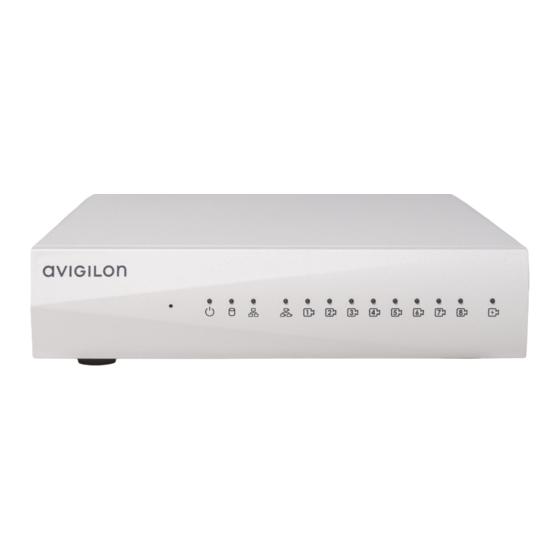
Front View
Rear View
Supported Network Configurations
Setting up the ENVR2 Plus Appliance
Installing the Hardware
Mounting to the Wall with the Supplied Brackets
Connecting the Hardware
Connect to the ENVR2 Plus Appliance (Using DHCP)
Connecting to the ENVR2 Plus Appliance (Using Static IP)
Configuring the ENVR2 Plus Appliance for the First Time
Troubleshooting
Network Configuration
Monitoring System Health
Installing the ACC Client
Activate the ACC Software and Connect to Avigilon Cloud Services
Activate ACC Software and Feature Licenses
Connect to Avigilon Cloud Services
Activating a License
Online Activation
Offline Activation
Reactivating a License
Starting up and Shutting down the ACC Client Software
Enabling Analytics on an ENVR2 Plus Appliance
Setting up License Plate Recognition
LPR Performance Mode
Using Server Management
Starting and Stopping Server Management
Viewing Poe Port Status
Manage ACC Services
Enable ACC Client Users to Archive Video
Provide Server Logs and System Logs for Support
Manage Device Settings
Change the ENVR2 Plus Appliance Administrator Password
Manage Time Settings
Manage Storage
Connect the Device to Cameras and ACC Client Users
Assigning a Poe Power Budget
Providing Device Logs for Support
Connecting to External Devices
LED Indicators
Front Panel Leds
Back Panel Leds
Budgeting Poe Power
Manage Certificates
Replace the Web Certificate
Upload a Trusted CA Certificate
Upgrade the Firmware
Using the Reset Button
Restarting the System
Restoring Factory Default Settings
Mounting with the Optional Rack Mount Kit
Mounting with the Optional DIN Rail Mount Kit
For more Information
Advertisement
Quick Links
1
Web Browser
2
Networking
3
Passwords
4
Setting up the Envr2 Plus Appliance
5
Network Configuration
Download this manual
User Guide
Avigilon ENVR2 Plus Appliance
ENVR2-PLUS-8P4
ENVR2-PLUS-8P8
Table of
Contents
Previous
Page
Next
Page
1
2
3
4
5
Advertisement
Table of Contents
Need help?
Do you have a question about the ENVR2 Plus and is the answer not in the manual?
Ask a question
Questions and answers
Related Manuals for Avigilon ENVR2 Plus
Measuring Instruments Avigilon ACC VMA-RPO-4P2 User Manual
Es hd recorder (37 pages)
Network Hardware Avigilon ENVR1 User Manual
(55 pages)
Network Hardware Avigilon VMA-AS1-8P User Manual
Hd video appliance (29 pages)
Network Hardware Avigilon VMA-RPO-4P4 User Manual
(28 pages)
Network Hardware Avigilon NVR6-AINVR2-FORM-D-10GBE Installation Manual
(17 pages)
Network Hardware Avigilon NVR5 User Manual
(15 pages)
Network Hardware Avigilon 3 Series User Manual
Video appliance (59 pages)
Network Hardware Avigilon AI NVR Installation Manual
Nvr standard 10gbe kit for ainvr-std (16 pages)
Network Hardware Avigilon VMA-AIA1-CG1 User Manual
Avigilon artificial intelligence appliance (31 pages)
Network Hardware Avigilon NVR5 Premium Installation Manual
(30 pages)
Network Hardware Avigilon VMA-AS3X-IPMI Installation And Operation Manual
(57 pages)
Network Hardware Avigilon NVR4-VAL-6TB Manual
(15 pages)
Network Hardware Avigilon HD-NVR3-STD-24TB Installation Manual
(29 pages)
Network Hardware Avigilon AINVR-STD-PRK Installation Manual
Standard performance kit (18 pages)
Network Hardware Avigilon ACC VMA-ENVR1-8P4 User Manual
Es 8 port appliance (42 pages)
Network Hardware Avigilon VMA-AIA1-CG1-UPGK Installation Manual
Ai appliance 1 to ai appliance 2 upgrade kit (19 pages)
This manual is also suitable for:
Envr1
Envr2-plus-8p4
Envr2-plus-8p8
Table of Contents
Save PDF
Print
Rename the bookmark
Delete bookmark?
Delete from my manuals?
Login
Sign In
OR
Sign in with Facebook
Sign in with Google
Upload manual
Upload from disk
Upload from URL


Need help?
Do you have a question about the ENVR2 Plus and is the answer not in the manual?
Questions and answers