
Related Manuals for Eneo APD-7SV2812MVA


Summary of Contents for Eneo APD-7SV2812MVA
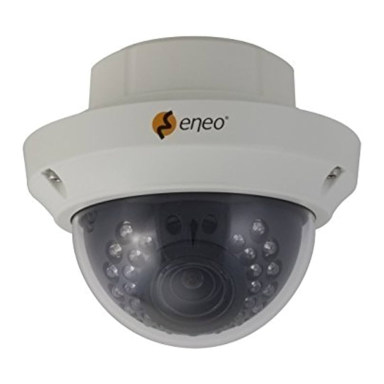
- Page 1 Installation Guide 1/3” Dome, Day&Night, E o-V(WDR)/E o-A(D-WDR), 2.8~12mm, 750TVL, Infrared, 12/24V, IP67 APD-7SV2812MVA APD-7SV2812MAA...
-
Page 3: Safety Precaution
ULTRA CLEAR RESOLUTION CAMERA Safety Precaution To prevent fire or shock hazard, do not expose the unit to rain or moisture. To prevent electric shocks and risk of fire hazards, do NOT use other than specific power source. CAUTION: TO REDUCE THE RISK OF ELECTIRC SHOCK, DO NOT REMOVE COVER (OR BACK). - Page 4 ULTRA CLEAR RESOLUTION CAMERA Safety Precaution NOTICE The image used in this instruction manual are processed to help comprehension and may differ from actual video of the camera. Avoid installing areas where has shock or vibration which results in the problems. Pay attention to safety when laying the connection cable and observe that the cable is not subjected to heavy loads, kinks or damage and no moisture can get in.
-
Page 5: Table Of Contents
ULTRA CLEAR RESOLUTION CAMERA Contents p.03~04 Safety Precaution p.05 Contents p.06 Features p.07 Composition p.08 Dimensions p.09 Part Names p.10~13 Installation Instructions p.14~33 Operating Instructions p.34~35 Specifications... -
Page 6: Features
Key Features • 1/3” High density Sony CCD (960H) • 750TVL High-Resolution • True WDR (Wide Dynamic Range) : APD-7SV2812MVA • D-WDR by ATR-EX : APD-7SV2812MAA • TDN with Dual Filter Switcher • Built-in f=2.8~12mm F1.4 Mega pixel DC Auto Iris Vari-focal Lens •... -
Page 7: Composition
- Delivers the crystal clear images providing 750TVL resolution in conjunction with SONY 960H High density CCD. - APD-7SV2812MVA is provided ‘TRUE WDR’ function - APD-7SV2812MAA is provided ‘D-WDR by ATR-EX’ function - Color signal processing provides the optimum balance between the luminance and chroma signals for high color reproducibility even for the detail scene which contains very high spatial frequency. -
Page 8: Dimensions
ULTRA CLEAR RESOLUTION CAMERA Dimensions (unit : mm) Ø140 Ø102 Ø140 PCD Ø120 3-Ø4.2... -
Page 9: Part Names
ULTRA CLEAR RESOLUTION CAMERA Part Names POWER CABLE FLUSH MOUNT OSD CONTROL JOY STICK FOCUS / ZOOM LENS SAFTY WIRE 3-AXIS GIMBAL DOME COVER BUBBLE DOME [ BOTTOM VIEW ] POWER CABLE POWER CABLE VIDEO (BNC) POWER SUPPLY CONNECTOR... -
Page 10: Installation Instructions
ULTRA CLEAR RESOLUTION CAMERA Installation Instructions 1. Locate the mounting template at the installation position and drill the ceiling or wall if needed. 2. Open the dome cover by loosening screws(4x12mm). Use the torque wrench supplied. - Place the dome base unit on pre-drilled position and fix it through using mounting screws (4x30mm). - Page 11 ULTRA CLEAR RESOLUTION CAMERA Installation Instructions Option 1. ■ Installation with Flush mount / Tilted Junction mount ① Cable is unfixed on the Dome base. ② Connect the power cable to their repective connections. * Refer to the instruction guide for Tilted Junction mount . Option 2.
- Page 12 ULTRA CLEAR RESOLUTION CAMERA Installation Instructions Limit of pan & tilt 1) Pan limit: Pan is limited to +/- 173°. Do NOT force to rotate the gimbal over the limit to prevent from the internal damage. 2) Tilt limit: Tilt is limited to 25° min ~ 90° max. with reference to the ceiling when the inclination of camera module is 0°, that is, the image is aligned horizontally.
-
Page 13: Operating Instructions
ULTRA CLEAR RESOLUTION CAMERA Operating Instructions Installation and commissioning Instructions • Make sure the power is removed before the installation. • Follow the order for applying power. First, connect the low voltage (AC24V or DC12V), then plug the AC adapter to AC outlets to avoid an improper reset from power jitter and a damage from the surge voltage when no load. - Page 14 ULTRA CLEAR RESOLUTION CAMERA Operating Instructions Using OSD controller Setup menu can be accessed and controlled by OSD control joy stick on the side of camera unit. Five commands are available with the joy stick. The design of OSD could be different according to the Model. OSD Control Joy Stick Video Sub-out Connector...
- Page 15 ULTRA CLEAR RESOLUTION CAMERA Operating Instructions OSD menu Startup Press the ‘OSD menu SET key’ down to access the setup menu mode. • : Selects previous page or next page. • EXIT : Enters ‘EXIT’ menu. • RETURN : Returns to the previous menu. SETUP MENU SETUP MENU 1 / 2...
- Page 16 ULTRA CLEAR RESOLUTION CAMERA Operating Instructions WDR for V-Series, ATR-EX for A-Series WDR / ATR-EX SCENE SELECT LEVEL AUTO DAY/NIGHT BURST CNTL SIGNAL EXT1 DELAY CNT DAY->NIGHT NIGHT->DAY NIGHT BURST MODE IR OPTIMIZER AUTO IR AREA LEVEL IR LED DAY/NIGHT / OFF/ FIX COLOR NIGHT OFF / ON...
- Page 17 ULTRA CLEAR RESOLUTION CAMERA Operating Instructions POSITION PRIVACY MASK COLOR TRANSP MOSAIC OFF (default) MOTION DET DETECT SENSE INTERVAL BLOCK DISP MASK AREA MONITOR AREA AREA SEL AREA MODE BOTTOM LEFT RIGHT TYPE LENS AUTO SYS SETTING MODE AUTO ADJUST SPEED FLIP OFF / V / H / HV...
- Page 18 ULTRA CLEAR RESOLUTION CAMERA Operating Instructions OSD menu Setup Press the OSD menu SET key down to access the setup menu mode. SETUP MENU ADVANCED MENU 1 / 2 1 / 2 SCENE SELECT FULL AUTO AUTO SHUTTER/AGC PICT ADJUST WHITE BAL EZOOM HLC/BLC...
- Page 19 ULTRA CLEAR RESOLUTION CAMERA Operating Instructions 1-1-2. MANUAL: Video level is manually controlled by the settings of SHUTTER, AGC MAX. In this mode, ‘DC Auto Iris Lens’ is only available. 1-1-3. FIX: Video level is fixed in any conditions by the setting of SHUTTER, AGC MAX. 1-2.
- Page 20 ULTRA CLEAR RESOLUTION CAMERA Operating Instructions • ENVIRONMENT (default: INDOOR): Selects INDOOR, SUNNY, SHADE or AUTO Their ATW is optimized for the limited application and can not cover > INDOOR : Optimized for Indoor installation and more easily compensates ATW for low color temperature such as incandescent lights.
- Page 21 ULTRA CLEAR RESOLUTION CAMERA Operating Instructions 1-3-2. HLC: HLC clips out the highlight area and masks it as black color. Video will be clipped out and masked for the area which exceeds CLIP LEVEL. • CLIP LEVEL (default: 010): Defines the threshold level for HLC. Lower value masks more. 1-3-3.
- Page 22 ULTRA CLEAR RESOLUTION CAMERA Operating Instructions 1-6. DAY/NIGHT This function is used to control the setting during day-time and night-time operation. 1-6-1. AUTO AUTO mode in DAY/NIGHT is used only for a camera which does not have a light sensor. Camera switches DAY from/to NIGHT automatically along with the amount of light through the lens.
- Page 23 ULTRA CLEAR RESOLUTION CAMERA Operating Instructions • NIGHT -> DAY (default: 120) NIGHT→DAY is a threshold level which determines to switch from NIGHT to DAY. Lower(Higher) value makes the camera switched from Night to Day at lower(higher) illumination. If it stays in Night(B/W) mode at day time, decrease NIGHT->DAY threshold value until it just switches to Day * Examine and verify Day/Night operation according to IMPORTANT ACTIVITY 1-6-2.
- Page 24 ULTRA CLEAR RESOLUTION CAMERA Operating Instructions 1-7. IR OPTIMIZER (default: OFF) This function is effective built-in LED models in NIGHT mode only. If subjects which can cause overexposure are located near the monitored area, you can adjust IR OPTIMIZER level or area. IR OPTIMIZER ON IR OPTIMIZER OFF ●...
- Page 25 ULTRA CLEAR RESOLUTION CAMERA Operating Instructions 1-7-4. IR LED: Sets the IR LED ON/OFF controlling • DAY/NIGHT : Follows the setting automatically DAY/NIGHT function. • OFF : Turns IR LED off. • FIX : Fixes the brightness of IR LED in any condition. IR LED AUTO IR LED FIX LEVEL MIN...
- Page 26 ULTRA CLEAR RESOLUTION CAMERA Operating Instructions 1-9. DEFOG (default: ON) This function is used to carry out defog function. Sets LEVEL to eliminate amount of fog on screen. If the DEFOG is set to ON, the WDR/BLC function will be deactivated. 1-10.
- Page 27 ULTRA CLEAR RESOLUTION CAMERA Operating Instructions 2-5. COLOR GAIN (default: 128): Increases or decreases the color saturation. 3. EZOOM (default: OFF): Sets the maximum digital zoom magnification. E.ZOOM function enlarges the pixel itself, which can cause deterioration of the picture quality. 3-1.
- Page 28 ULTRA CLEAR RESOLUTION CAMERA Operating Instructions 5-2. DISPLAY (default: OFF) Displays OFF/ON for the mask area which you selected ‘AREA SEL’ 5-3. POSITION : Adjusts the mask area X,Y-Axis position which you selected ‘AREA SEL’ • TOP/BOTTOM: ◄button moves up and ►button moves down the top (bottom) border of the selected window at AREA SEL.
- Page 29 ULTRA CLEAR RESOLUTION CAMERA Operating Instructions 6-4. MASK AREA 9 10 11 12 Sets MASK AREA for disabling 13 14 15 16 17 18 19 20 21 22 23 24 MOTION DETECTION. 25 26 27 28 29 30 31 32 33 34 35 36 Selects number of area sels to 37 38 39 40 41 42 43 44 45 46 47 48 set the area you need.
- Page 30 ULTRA CLEAR RESOLUTION CAMERA Operating Instructions 7. SYS SETTING Sets the system related functions. 7-1. LENS SYSTEM SETTING Selects the lens type, AUTO or MANUAL. AUTO supports DC LENS AUTO auto-iris lens only. FLIP LCD/CRT 7-1-1. AUTO COMMUNICATION CAMERA ID •...
- Page 31 ULTRA CLEAR RESOLUTION CAMERA Operating Instructions 7-5. CAMERA ID Sets ON/OFF for enabling/disabling of ID display. Factory default ID is Software version of camera. User programmed camera ID will be lost and restored with factory default ID by CAMERA RESET. Up to 40 characters can be input for camera ID.
- Page 32 ULTRA CLEAR RESOLUTION CAMERA Operating Instructions 10. MAINTENANCE Sets the OSD menu user environments and Camera reset. MAINTENANCE MANUAL W.PIX MASK CAMERA RESET RETURN 10-1. W.PIX MASK This function is used to compensate white pixels(defective pixels). MANUAL COMP AUTO COMP REGISTRATION LEVEL1 REG.POINT...
- Page 33 ULTRA CLEAR RESOLUTION CAMERA Operating Instructions 10-1-3. DATA CLEAR : Clear the W.PIX data or not. 10-2. CAMERA RESET This function is used to reset to the factory defaults of the camera settings. RESET and EXIT the OSD menu. 11. EXIT Exits SETUP MENU and returns to the normal display.
-
Page 34: Specifications
ULTRA CLEAR RESOLUTION CAMERA Specifications ITEM APD-7SV2812MVA Imaging Sensor 1/3" High density double scan Sony CCD (960H) Effective Pixels 976(H) x 582(V) Scan Frequency 50Hz(V), 15.625Khz(H) / 2:1 Interlace Synchronization Internal H. Resolution 750TV Lines Sensitivity 0.1 Lux (F1.4@40 IRE, Sens-up Off) - Page 35 ULTRA CLEAR RESOLUTION CAMERA Specifications ITEM APD-7SV2812MAA Imaging Sensor 1/3" High density Sony CCD (960H) Effective Pixels 976(H) x 582(V) Scan Frequency 50Hz(V), 15.625Khz(H) / 2:1 Interlace Synchronization Internal H. Resolution 750TV Lines Sensitivity 0.1 Lux (F1.4@40 IRE, Sens-up Off) S/N Ratio 52dB with AGC OFF at 50 IRE Electronic Iris...
- Page 36 VIDEOR E. Hartig GmbH Exclusive distribution through specialised trade channels only. VIDEOR E. Hartig GmbH Carl-Zeiss-Straße 8 63322 Rödermark/Germany Tel. +49 (0) 6074 / 888-0 Technical changes reserved Fax +49 (0) 6074 / 888-100 ©...
Need help?
Do you have a question about the APD-7SV2812MVA and is the answer not in the manual?
Questions and answers