
Related Manuals for DSE DSE705


Summary of Contents for DSE DSE705
- Page 1 COMPLEX SOLUTIONS MADE SIMPLE DEEP SEA ELECTRONICS PLC DSE705 ATS CONTROL MODULE OPERATING MANUAL...
- Page 2 Website: www.deepseaplc.com DSE Model 704 Control System Operators Manual © Deep Sea Electronics Plc All rights reserved. No part of this publication may be reproduced in any material form (including photocopying or storing in any medium by electronic means or other) without the written permission of the copyright holder except in accordance with the provisions of the Copyright, Designs and Patents Act 1988.
-
Page 3: Table Of Contents
705 ATS controller operators manual TABLE OF CONTENTS 1 INTRODUCTION ................... 4 2 DESCRIPTION OF OPERATION ............4 2.1 MANUAL RUN ON LOAD ................. 4 2.2 MANUAL RUN OFF LOAD ................4 2.3 AUTOMATIC MODE OF OPERATION ............. 5 3 CONFIGURATION INSTRUCTIONS ............. 6 4 CONFIGURATION TABLES .............. -
Page 4: Introduction
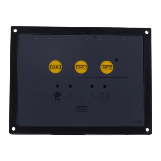
705 ATS controller operators manual 1 INTRODUCTION The 705 is a configurable Automatic Transfer Switch control module, and is designed to work in conjunction with generator control modules that will accept a remote start input. It monitors the incoming AC mains supply (1 or 3 phases) for under voltage. If the voltage falls out of limits the module will issue a start command to the generating set controller. -
Page 5: Automatic Mode Of Operation
705 ATS controller operators manual 2.3 AUTOMATIC MODE OF OPERATION This mode is activated by pressing the pushbutton. An LED indicator beside the button confirms this action. Whether the start sequence is initiated by mains (utility) failure, or by remote start input, the following sequence id followed: To allow for short term mains supply transient conditions or false remote start signals, the Mains Fail Delay timer is initiated. -
Page 6: Configuration Instructions
705 ATS controller operators manual 3 CONFIGURATION INSTRUCTIONS ♦ With the unit in Auto mode, Configuration Mode is selected by operation of a small switch on the rear, left-hand edge of the PCB. This is partially hidden to prevent accidental operation. -
Page 7: Configuration Tables
705 ATS controller operators manual 4 CONFIGURATION TABLES FUNCTIONS AND CONFIGURATION TABLE Function Value (Default in Bold) Start Delay 0 Seconds 5 Seconds 10 Seconds 15 Seconds 20 Seconds 30 Seconds 60 Seconds 180 Seconds Used to give a delay between mains failure and starting the engine. Used to prevent the generating from starting on brown outs (dips) or short mains outages. - Page 8 705 ATS controller operators manual FUNCTIONS AND CONFIGURATION TABLE Function Value (Default in Bold) Remote Start Remote Start Is Off load Function Remote Start Is On Load The remote start input can be configured to one of the following. ♦ Remote start is off load –...
-
Page 9: Terminal Description
DC Plant Supply Input 1.0mm Connected to plant battery positive (+ve) (Recommended Fuse 2A) Remote Start Output 1.0mm Remote Start Input to all DSE modules. Auxiliary Output relay 1 1.0mm Configurable output. Auxiliary Output relay 2 1.0mm Configurable output. NOT USED... -
Page 10: Specification
705 ATS controller operators manual 6 SPECIFICATION DC Supply: 8 Volts to 35 Volts DC Continuous. Cranking Dropouts: Able to survive 0 Volts for 50 mS, providing supply was at least 10 V before dropout and supply recovers to 5 Volts. This is achieved without the need for internal batteries. -
Page 11: Solid State Outputs
To Positive supply via fuse To Fuel Solenoid Example of relay pins connected to DSE solid state output to drive a fuel solenoid. See overleaf for overall typical wiring diagram NOTE: - The Close Mains Relay should be NORMALLY CLOSED when de-energised for fail safe reasons. -
Page 12: Dimensions
(see note) NOTES : The remote start inputs of all DSE modules can be connected directly to the start/run output (terminal 3) of the 705 ATS controller, providing that the DC supplies are common to each module. Wiring of remote start relay above is shown for connection to an engine controller requiring a battery negative signal Battery to start the set (such as DSE controllers). - Page 13 705 ATS controller operators manual << This page is intentionally blank >> 057-043 705 Operating Instructions Issue 1.1 18/06/2007 - 13 -...
Need help?
Do you have a question about the DSE705 and is the answer not in the manual?
Questions and answers