Table of Contents
Advertisement
Quick Links
DSEPOWER
SHARING
WITH
SIMPLICITY.
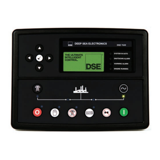
DSE7520
AUTO MAINS (UTILITY) FAILURE & INSTRUMENTATION CONTROL MODULE
The DSE7520 is an Automatic
Mains (Utility) Failure Control
Module designed to provide
advanced load share functionality
for diesel and gas generating sets
that include non electronic and
electronic engines, for single set
applications and parallel with
mains. The module also provides
excellent monitoring and protection
features.
The module monitors the mains
(utility) supply and upon detection
of a loss in power automatically
starts the generating set.
The module's synchronising
functions include automatic
synchronising with built in
synchroscope and closing onto dead
bus. Direct and flexible outputs from
the module are provided to allow
connection to the most commonly
used speed governors and
automatic voltage regulators (AVRs).
The module has the ability to
monitor generator under/over
volts, over current, generator
under/over frequency, under
speed, over speed, charge fail,
emergency stop, low oil pressure,
high engine temperature, fail to
start, low/high DC battery volts, fail
to stop, generator short circuit
protection, reverse power,
generator phase rotation error,
earth fault protection, loss of
speed signal, fail to open, fail to
close, out of sync, open circuit
failure, negative phase sequence
and loss of excitation.
FEATURES
•
Electronic engine capability
•
RS232 or RS485 remote
•
Modbus RTU
•
Pin number protected front panel
programming
•
Exercise timer
•
Back-lit LCD 4-line text display
•
Multiple language options
•
Voltage measurement
•
Configurable inputs (9)
•
Configurable outputs (5)
•
Automatic start
•
Manual start
•
Audible alarm
•
LED indicators
•
Built-in governor and AVR control
for easy operation and panel
engineering
•
Engine history event log
•
Engine protection
•
Fault condition notification to a
designated PC
•
Front panel mounting
•
PC configuration
•
Mains (utility) failure detection
•
Configurable alarm timers
•
Configurable start & stop timers
•
Automatic load transfer
•
SMS alert messaging
•
Multi set communications
•
Front panel mounting
•
Remote control and monitoring
•
Dedicated load test button
•
kW overload alarms
•
Engine temperature alarms
•
MV-LV synching
®
ELECTRONIC ENGINE CAPABILITY
LOAD SHARE FEATURES
•
No-break transfer
•
Peak shaving/peak lopping
•
kW on mains (utility) level
•
Mains (utility) decoupling test mode
•
Manual speed/frequency adjust
•
ROCOF & vector shift
•
Dead bus sensing
•
Direct governor & AVR
communication
•
Volts & frequency matching
•
kW and kVar load sharing
•
Manual voltage adjust
BENEFITS
•
Sends SMS messages to
engineers to notify specific engine
problems (GSM Modem and SIM
card required)
•
On-site and remote module
configuration (Modem required)
•
In-built engine diagnostics
removes the requirement for
service equipment
•
Full engine protection &
instrumentation without the need
for additional senders (Electronic
engines only)
•
Remote monitoring of the module
using comprehensive DSE PC
software
•
License free PC software
•
No-break return capability
SPECIFICATION
DC SUPPLY
8V to 35V continuous
CRANKING DROPOUTS
Able to survive 0V for 50mS, providing supply
was at least 10V before dropout and supply
recovers to 5V. This is achieved without the
need for internal batteries
MAXIMUM OPERATING CURRENT
460mA at 12V. 245mA at 24V
MAXIMUM STANDBY CURRENT
375mA at 12V. 200mA at 24V
ALTERNATOR INPUT RANGE
15V(L-N) to 333V AC (L-N) absolute maximum
ALTERNATOR INPUT FREQUENCY
50Hz - 60Hz at rated engine speed (Minimum:
15V AC L-N)
MAGNETIC PICK-UP VOLTAGE RANGE
+/- 0.5V to 70V Peak
1,000 Hz to 10,000 Hz
MAINS (UTILITY) SENSING RANGE
15V(L-N) to 333V AC (L-N) absolute maximum
MAINS (UTILITY) SENSING INPUT
FREQUENCY
50Hz-60Hz (Minimum: 15V AC L-N)
START OUTPUT
15A DC at supply voltage
FUEL OUTPUT
15A DC at supply voltage
AUXILIARY OUTPUTS
Three outputs 2A DC at supply voltage
Two outputs volt free 8A at 250V AC
GENERATOR LOADING RELAY OUTPUT
8A AC 250V AC
MAINS (UTILITY) LOADING RELAY OUTPUT
8A AC 250V AC
CHARGE FAIL/EXCITATION RANGE
0V to 35V
Fixed power source 2.5W
BUILT-IN GOVERNOR AND AVR CONTROL
Fully Isolated
Minimum Load Impedance:
1000Ω
Gain Volts: 0V-10V DC
Offset Volts: + / - 10V DC
DIMENSIONS
240mm x 172mm x 57mm
9.4" x 6.8" x 2.2"
PANEL CUTOUT
220mm x 160mm
8.7" x 6.3"
DEGREES OF PROTECTION PROVIDED
BY ENCLOSURES
BS EN 60529
IP65 - Front of module when installed into the
control panel with the supplied sealing gasket.
®
Advertisement
Table of Contents

Related Manuals for DSE DSE7520


Summary of Contents for DSE DSE7520
- Page 1 15V AC L-N) MAGNETIC PICK-UP VOLTAGE RANGE +/- 0.5V to 70V Peak 1,000 Hz to 10,000 Hz The DSE7520 is an Automatic failure, negative phase sequence MAINS (UTILITY) SENSING RANGE 15V(L-N) to 333V AC (L-N) absolute maximum Mains (Utility) Failure Control and loss of excitation.
- Page 2 Three shocks in each of three major axes 15gn in 11mS The DSE7520 module provides advanced metering and alarm functionality condition, it dials out to a PC via the LCD display. The information can be accessed using the display scroll notifying the user of the exact alarm pushbuttons.
- Page 3 DSE7520 Installation Instructions 053-053 DSE75xx PC Software Manual 057-078 DSE7510 Data Sheet 055-065 DSE7560 Data Sheet 055-067 Load Share Design and Commissioning 057-047 Guide to Synchronising and Load Sharing 057-045/6 CAN and DSE Wiring Guide 057-004 DSE850 Comms Software Data Sheet 055-072...
- Page 4 DEEP SEA ELECTRONICS PLC TELEPHONE EMAIL ® Highfield House +44 (0)1723 890099 sales@deepseaplc.com Hunmanby Industrial Estate Hunmanby, North Yorkshire FACSIMILE WEBSITE YO14 0PH England +44 (0)1723 893303 www.deepseaplc.com Registered in England & Wales No.01319649 VAT No.316923457 DEEP SEA ELECTRONICS INC TELEPHONE EMAIL 3230 Williams Avenue...
Need help?
Do you have a question about the DSE7520 and is the answer not in the manual?
Questions and answers