
Related Manuals for DSE DSE7210


Summary of Contents for DSE DSE7210
-
Page 1: Deep Sea Electronics
DEEP SEA ELECTRONICS DSE7200 / 7300 Series Operators Manual Document Number: 057-074 Author: Anthony Manton DSE7200 / 7300 Series Operators Manual ISSUE 13... - Page 2 Applications for the copyright holder’s written permission to reproduce any part of this publication should be addressed to Deep Sea Electronics Plc at the address above. The DSE logo and the names are UK registered trademarks of Deep Sea Electronics PLC. Any reference to trademarked product names used within this publication is owned by their respective companies.
- Page 3 DSE7200 / 7300 Series Operators Manual Amendments since last publication Amd. No. Comments Added Maintenance Alarm Added manual fuel pump and manual speed control (Issue 2.1) Added more detail to many sections of the manual (Issue 2.1) including CTs, Earth Fault, Overcurrent, RS232, Modem, RS485, external sounder, expansion modules (DSE2100 series), Added changes to Dual Mutual, Fuel usage, dummy load control, load shedding, protections disabled, 2500 series display (for version 4 module additions)
-
Page 4: Table Of Contents
DSE7200 / 7300 Series Operators Manual TABLE OF CONTENTS Section Page DEEP SEA ELECTRONICS ................... 1 BIBLIOGRAPHY ....................8 INSTALLATION INSTRUCTIONS .................. 8 TRAINING GUIDES ......................8 MANUALS ........................8 THIRD PARTY DOCUMENTS ..................8 INTRODUCTION ....................9 SPECIFICATIONS ..................10 PART NUMBERING ...................... - Page 5 4.4.9 CT LOCATION ....................... 56 TYPICAL ARRANGEMENT OF DSENET® ..............57 DESCRIPTION OF CONTROLS ..............58 DSE7210 / DSE7310 AUTOSTART CONTROL MODULE ..........58 DSE7220 / DSE7320 AMF CONTROL MODULE ............60 QUICKSTART GUIDE ....................62 5.3.1 STARTING THE ENGINE ..................62 5.3.2...
- Page 6 COMMISSIONING ..................113 9.1.1 PRE-COMMISSIONING ..................113 FAULT FINDING ..................114 MAINTENANCE, SPARES, REPAIR AND SERVICING ......116 11.1 PURCHASING ADDITIONAL CONNECTOR PLUGS FROM DSE ......116 11.1.1 DSE7200 SERIES ....................116 11.1.1.1 PACK OF PLUGS ............................116 11.1.1.2 INDIVIDUAL PLUGS ..........................116 11.1.2...
- Page 7 DSE7200 / 7300 Series Operators Manual WARRANTY ....................120 DISPOSAL ....................120 13.1 WEEE (WASTE ELECTRICAL AND ELECTRONIC EQUIPMENT) ......120 13.2 ROHS (RESTRICTION OF HAZARDOUS SUBSTANCES) ........120...
-
Page 8: Bibliography
DSE7200 / 7300 Series Operators Manual 1 BIBLIOGRAPHY This document refers to and is referred to by the following DSE publications which can be obtained from the DSE website www.deepseaplc.com 1.1 INSTALLATION INSTRUCTIONS Installation instructions are supplied with the product in the box and are intended as a ‘quick start’ guide only. -
Page 9: Introduction
2 INTRODUCTION This document does not contain operating instructions for the DSE7500 series synchronising and load sharing controllers. This is contained within DSE publications - part numbers 057-088 (DSE7510), 057-089 (DSE7520) and 057-090 (DSE7560). This document details the installation and operation requirements of the DSE7200 and DSE7300 Series modules, part of the DSEControl®... -
Page 10: Specifications
Change to maximum AC Voltage and CAN port isolation This document does not contain operating instructions for the DSE7500 series synchronising and load sharing controllers. This is contained within DSE publications - part numbers 057-088 (DSE7510), 057-089 (DSE7520) and 057-090 (DSE7560). 3.2 MODEL NAMING... -
Page 11: Short Names
10 way connector Maximum cable size 2.5mm² (AWG 10) NOTE : For purchasing additional connector plugs from DSE, please see the section entitled Maintenance, Spares, Repair and Servicing elsewhere in this document. 3.5 POWER SUPPLY REQUIREMENTS Minimum supply voltage... -
Page 12: Generator And Mains Voltage / Frequency Sensing
DSE7200 / 7300 Series Operators Manual 3.6 GENERATOR AND MAINS VOLTAGE / FREQUENCY SENSING 3.6.1 GENERAL Measurement type True RMS conversion Sample Rate 5KHz or better Harmonics Up to 10 or better 300K Ω ph-N Input Impedance Common mode offset from Earth 100V AC (max) 3.6.2 VOLTAGE SENSING See section entitled Part Numbering elsewhere in this document to identify the Hardware Version of the controller... -
Page 13: Current Sensing
DSE7200 / 7300 Series Operators Manual 3.7 CURRENT SENSING Measurement type True RMS conversion Sample Rate 5KHz or better Harmonics Up to 10 or better Nominal CT secondary rating 1A or 5A (5A recommended) Maximum continuous current Overload Measurement 3 x Nominal Range setting Absolute maximum overload 50A for 1 second Burden... -
Page 14: Inputs
DSE7200 / 7300 Series Operators Manual 3.8 INPUTS 3.8.1 DIGITAL INPUTS DSE7200 Number DSE7300 Arrangement Contact between terminal and ground Low level threshold 2.1V minimum High level threshold 6.6V maximum Maximum input voltage +50V DC with respect to plant supply negative Minimum input voltage -24V DC with respect to plant supply negative Contact wetting current... -
Page 15: Fuel Level
DSE7200 / 7300 Series Operators Manual 3.8.2.3 FUEL LEVEL Measurement type Resistance measurement by measuring voltage across sensor with a fixed current applied Arrangement Differential resistance measurement input Measurement current 10mA Full scale 480Ω Over range / fail 540Ω Resolution Accuracy +/-2% of full scale resistance (±9.6Ω) excluding transducer error Max common mode... -
Page 16: Magnetic Pickup
Flywheel teeth 10 to 500 NOTE : DSE can supply a suitable magnetic pickup device, available in two body thread lengths : DSE Part number 020-012 - Magnetic Pickup probe 5/8 UNF 2½” thread length DSE Part number 020-013 - Magnetic Pickup probe 5/8 UNF 4” thread length Magnetic Pickup devices can often be ‘shared’... -
Page 17: Communication Ports
DSE7000 series to access these engine parameters with no physical connection to the sensor device. NOTE: - For further details for connections to CAN enabled engines and the functions available with each engine type, refer to the manual Electronic Engines and DSE Wiring. Part No. 057-004... -
Page 18: Usb Connection
The USB port is provided to give a simple means of connection between a PC and the DSE7000 series controller. Using the DSE Configuration Suite Software, the operator is then able to control the module, starting or stopping the generator, selecting operating modes, etc. -
Page 19: Rs232
GSM modem for more remote communications. Many PCs are not fitted with an internal RS232 serial port. DSE DOES NOT recommend the use of USB to RS232 convertors but can recommend PC add-ons to provide the computer with an RS232 port. - Page 20 • For a data connection to a PC running DSE Configuration Suite Software, a ‘special’ CSD (Circuit Switched Data) SIM card is required that will enable the modem to answer an incoming data call. Many...
-
Page 21: Rs485
One advantage of the RS485 interface is the large distance specification (1.2km when using Belden 9841 (or equivalent) cable. This allows for a large distance between the module and a PC running the DSE Configuration Suite software. The operator is then able to control the module, starting or stopping the generator, selecting operating modes, etc. -
Page 22: Dsenet® For Expansion Modules
While this is a very useful feature in some applications, the obvious drawback is that the DSENet® interface is no longer available for connection to expansion devices. Example of configuring the DSENet® for connection to Cummins QST GMC using the DSE Configuration Suite Software:... -
Page 23: Sounder
3.13.1 ADDING AN EXTERNAL SOUNDER TO THE APPLICATION Should an external alarm or indicator be required, this can be achieved by using the DSE Configuration Suite PC software to configure an auxiliary output for “Audible Alarm”, and by configuring an auxiliary input for “Alarm Mute”... -
Page 24: Dimensions And Mounting
DSE7200 / 7300 Series Operators Manual 3.15 DIMENSIONS AND MOUNTING DIMENSIONS 240.0mm x 181.1mm x 41.7mm (9.4” x 7.1” x 1.6”) PANEL CUTOUT 220mm x 160mm (8.7” x 6.3”) WEIGHT 0.7kg (1.4lb) -
Page 25: Fixing Clips
DSE7200 / 7300 Series Operators Manual 3.15.1 FIXING CLIPS Supplied fixing clips hold the module into the panel fascia. Withdraw the fixing clip screw (turn anticlockwise) until only the pointed end is protruding from the clip. • Insert the three ‘prongs’ of the fixing clip into the slots in the side of the 7000 series module case. •... -
Page 26: Cable Tie Fixing Points
DSE7200 / 7300 Series Operators Manual 3.15.2 CABLE TIE FIXING POINTS Integral cable tie fixing points are included on the rear of the module’s case to aid wiring. This additionally provides strain relief to the cable loom by removing the weight of the loom from the screw connectors, thus reducing the chance of future connection failures. -
Page 27: Applicable Standards
DSE7200 / 7300 Series Operators Manual 3.16 APPLICABLE STANDARDS BS 4884-1 This document conforms to BS4884-1 1992 Specification for presentation of essential information. BS 4884-2 This document conforms to BS4884-2 1993 Guide to content BS 4884-3 This document conforms to BS4884-3 1993 Guide to presentation BS EN 60068-2-1 -30°C (-22°F) (Minimum temperature) - Page 28 DSE7200 / 7300 Series Operators Manual IEEE C37.2 Continued (Standard Electrical Power 50 – Instantaneous overcurrent relay System Device Function 51 – AC time overcurrent relay Numbers and Contact 52 – AC circuit breaker Designations) 53 – Exciter or DC generator relay 54 –...
-
Page 29: Enclosure Classifications
DSE7200 / 7300 Series Operators Manual 3.16.1 ENCLOSURE CLASSIFICATIONS IP CLASSIFICATIONS 7000 series specification under BS EN 60529 Degrees of protection provided by enclosures IP65 (Front of module when module is installed into the control panel with the optional sealing gasket). IP42 (front of module when module is installed into the control panel WITHOUT being sealed to the panel) First Digit Second Digit... -
Page 30: Nema Classifications
DSE7200 / 7300 Series Operators Manual 3.16.2 NEMA CLASSIFICATIONS 7000 series NEMA Rating (Approximate) 12 (Front of module when module is installed into the control panel with the optional sealing gasket). 2 (front of module when module is installed into the control panel WITHOUT being sealed to the panel) NOTE: - There is no direct equivalence between IP / NEMA ratings. -
Page 31: Installation
DSE7200 / 7300 Series Operators Manual 4 INSTALLATION The DSE7000 Series module is designed to be mounted on the panel fascia. For dimension and mounting details, see the section entitled Specification, Dimension and mounting elsewhere in this document. 4.1 USER CONNECTIONS To aid user connection, icons on the rear of the module ease Identification of terminal functions. -
Page 32: Terminal Description
NOTE:- Terminals 12 to 14 are not fitted to the DSE7200/DSE7300 series controller. NOTE:- When the module is configured for operation with an electronic engine, FUEL and START output requirements may be different. Refer to Electronic Engines and DSE Wiring for further information. DSE Part No. 057-004. -
Page 33: Analogue Sensors
DSE7200 / 7300 Series Operators Manual 4.2.2 ANALOGUE SENSORS DESCRIPTION CABLE NOTES SIZE 0.5mm² Sensor Common Return Return feed for sensors AWG 20 0.5mm² Oil Pressure Input Connect to Oil pressure sensor AWG 20 0.5mm² Coolant Temperature Input Connect to Coolant Temperature sensor AWG 20 0.5mm²... -
Page 34: Magnetic Pickup, Can And Expansion
NOTE:- Screened 120Ω Ω Ω Ω impedance cable specified for use with CAN must be used for the CAN link and the Multiset comms link. DSE stock and supply Belden cable 9841 which is a high quality 120Ω Ω Ω Ω impedance cable suitable for CAN use (DSE part number 016-030) NOTE:- When the module is configured for CAN operation, terminals 22, 23 &... -
Page 35: Load Switching And Generator Voltage Sensing
DSE7200 / 7300 Series Operators Manual 4.2.4 LOAD SWITCHING AND GENERATOR VOLTAGE SENSING DESCRIPTION CABLE NOTES SIZE 1.0mm Normally configured to control mains contactor coil Output relay C AWG 18 (Recommend 10A fuse) 1.0mm Output relay C Normally configured to control mains contactor coil AWG 18 1.0mm Normally configured to control generator contactor coil... -
Page 36: Generator Current Transformers
(I1,I2,I3) s1 is the secondary of the CT that connects to the DSE Module’s input for the CT measuring s2 is the secondary of the CT that should be commoned with the s2 connections of all the other CTs and connected to the CT common terminal of the DSE7000 series modules. - Page 37 DSE7200 / 7300 Series Operators Manual Connection of CT s1 terminal DESCRIPTION CABLE NOTES SIZE 2.5mm² CT Secondary for Gen L1 Connect to s1 secondary of L1 monitoring CT AWG 13 2.5mm² CT Secondary for Gen L2 Connect to s1 secondary of L2 monitoring CT AWG 13 2.5mm²...
-
Page 38: Configurable Digital Inputs
DSE7200 / 7300 Series Operators Manual 4.2.7 CONFIGURABLE DIGITAL INPUTS DESCRIPTION CABLE NOTES SIZE 0.5mm² Configurable digital input A Switch to negative AWG 20 0.5mm² Configurable digital input B Switch to negative AWG 20 0.5mm² Configurable digital input C Switch to negative AWG 20 0.5mm²... -
Page 39: Rs485 Connector
DSE7200 / 7300 Series Operators Manual 4.2.9 RS485 CONNECTOR NOTE:- RS485 connector is not fitted to the 7200 series controller. PIN No NOTES Two core screened twisted pair cable. 120Ω impedance suitable for RS485 use. Recommended cable type - Belden 9841 Max distance 1000m (1km) when using Belden 9841 or direct equivalent. -
Page 40: Typical Wiring Diagrams
Genset manufacturers and panel builders may use these diagrams as a starting point, however you are referred to the completed system diagram provided by your system manufacturer for complete wiring detail. Further wiring suggestions are available in the following DSE publications, available at www.deepseaplc.com website members. -
Page 41: 7210 Autostart Controller
DSE7200 / 7300 Series Operators Manual 4.3.1 7210 AUTOSTART CONTROLLER 3 phase, 4 wire... -
Page 42: 7220 Amf Controller
DSE7200 / 7300 Series Operators Manual 4.3.2 7220 AMF CONTROLLER 3 phase, 4 wire... -
Page 43: 7310 Autostart Controller
DSE7200 / 7300 Series Operators Manual 4.3.3 7310 AUTOSTART CONTROLLER 3 phase, 4 wire with restricted earth fault protection NOTE:- Earthing the neutral conductor ‘before’ the neutral CT allows the module to read earth faults ‘after’ the CT only (Restricted to load / downstream of the CT) Earthing the neutral conductor ‘after’... -
Page 44: 7320 Amf Controller
DSE7200 / 7300 Series Operators Manual 4.3.4 7320 AMF CONTROLLER 3 phase, 4 wire with restricted earth fault protection NOTE:- Earthing the neutral conductor ‘before’ the neutral CT allows the module to read earth faults ‘after’ the CT only (Restricted to load / downstream of the CT) Earthing the neutral conductor ‘after’... -
Page 45: Dsenet
NOTE:- Screened 120Ω Ω Ω Ω impedance cable specified for use with CAN must be used for the DSENet® (RS485) connection. DSE stock and supply Belden cable 9841 which is a high quality 120Ω Ω Ω Ω impedance cable suitable for DSENet® use (DSE part number 016-030) -
Page 46: Connections For Dual Mutual Standby
RLY1 to call the input, instructing the set for the second set to start. to start. Screen capture from DSE Configuration Suite PC Software showing the configuration of the Master and Slave controllers. -
Page 47: Earth Systems
The typical wiring diagrams located within this document are designed and show connections for a negative earth system (the battery negative is connected to Earth) 4.3.7.2 POSITIVE EARTH When using a DSE module with a Positive Earth System (the battery positive is connected to Earth), the following points need to be followed : •... -
Page 48: Alternative Topologies
NOTE:- Further details of module configuration are contained within the DSE7000 Series configuration software manual (DSE part number 057-077) 4.4.1 3 PHASE, 4 WIRE WITHOUT EARTH FAULT PROTECTION NOTE:- Mains sensing (Terminals 47-50) is not fitted to DSE7210/ DSE7310 autostart controllers. -
Page 49: Single Phase With Restricted Earth Fault
V1.x.x modules have Earth fault measuring only (no protection alarms). NOTE:- Mains sensing (Terminals 47-50) is not fitted to DSE7210/ DSE7310 autostart controllers. NOTE:- Earthing the neutral conductor ‘before’ the neutral CT allows the module to read earth faults ‘after’... -
Page 50: Single Phase Without Earth Fault
DSE7200 / 7300 Series Operators Manual 4.4.3 SINGLE PHASE WITHOUT EARTH FAULT NOTE:- Mains sensing (Terminals 47-50) is not fitted to DSE7210/ DSE7310 autostart controllers. -
Page 51: Phase (L1 & L2) 3 Wire With Restricted Earth Fault
V1.x.x modules have Earth fault measuring only (no protection alarms). NOTE:- Mains sensing (Terminals 47-50) is not fitted to DSE7210/ DSE7310 autostart controllers. NOTE:- Earthing the neutral conductor ‘before’ the neutral CT allows the module to read earth faults ‘after’... -
Page 52: Phase (L1 & L2) 3 Wire Without Earth Fault
DSE7200 / 7300 Series Operators Manual 4.4.5 2 PHASE (L1 & L2) 3 WIRE WITHOUT EARTH FAULT NOTE:- Mains sensing (Terminals 47-50) is not fitted to DSE7210/ DSE7310 autostart controllers. -
Page 53: Phase (L1 & L3) 3 Wire With Restricted Earth Fault
V1.x.x modules have Earth fault measuring only (no protection alarms). NOTE:- Mains sensing (Terminals 47-50) is not fitted to DSE7210/ DSE7310 autostart controllers. NOTE:- Earthing the neutral conductor ‘before’ the neutral CT allows the module to read earth faults ‘after’... -
Page 54: Phase (L1 & L3) 3 Wire Without Earth Fault Measuring
DSE7200 / 7300 Series Operators Manual 4.4.7 2 PHASE (L1 & L3) 3 WIRE WITHOUT EARTH FAULT MEASURING NOTE:- Mains sensing (Terminals 47-50) is not fitted to DSE7210/ DSE7310 autostart controllers. -
Page 55: Phase 4 Wire With Unrestricted Earth Fault Measuring
4.4.8 3 PHASE 4 WIRE WITH UNRESTRICTED EARTH FAULT MEASURING NOTE:- Earth fault protection alarm only available on 7300 series V2.0 and above controllers. 7300 series V1.x.x modules have Earth fault measuring only (no protection alarms). NOTE:- Mains sensing (Terminals 47-50) is not fitted to DSE7210/ DSE7310 autostart controllers. -
Page 56: Ct Location
DSE7200 / 7300 Series Operators Manual 4.4.9 CT LOCATION NOTE:- CT Location is not applicable to the DSE7210 / DSE7310 autostart controllers. There are two possible locations for the current transformers in the system: 1) Generator : The CTs are used to measure and display generator current only. The typical wiring diagrams in the preceding section all show the CT measuring the generator load. -
Page 57: Typical Arrangement Of Dsenet
DSE7200 / 7300 Series Operators Manual 4.5 TYPICAL ARRANGEMENT OF DSENET® A total of twenty (20) devices can be connected to the DSENet®, made up of the following devices : Device Max number supported DSE2130 Input Expansion DSE2157 Output Expansion DSE2548 LED Expansion DSE2510 Display for DSE7310 DSE2520 Display for DSE7320... -
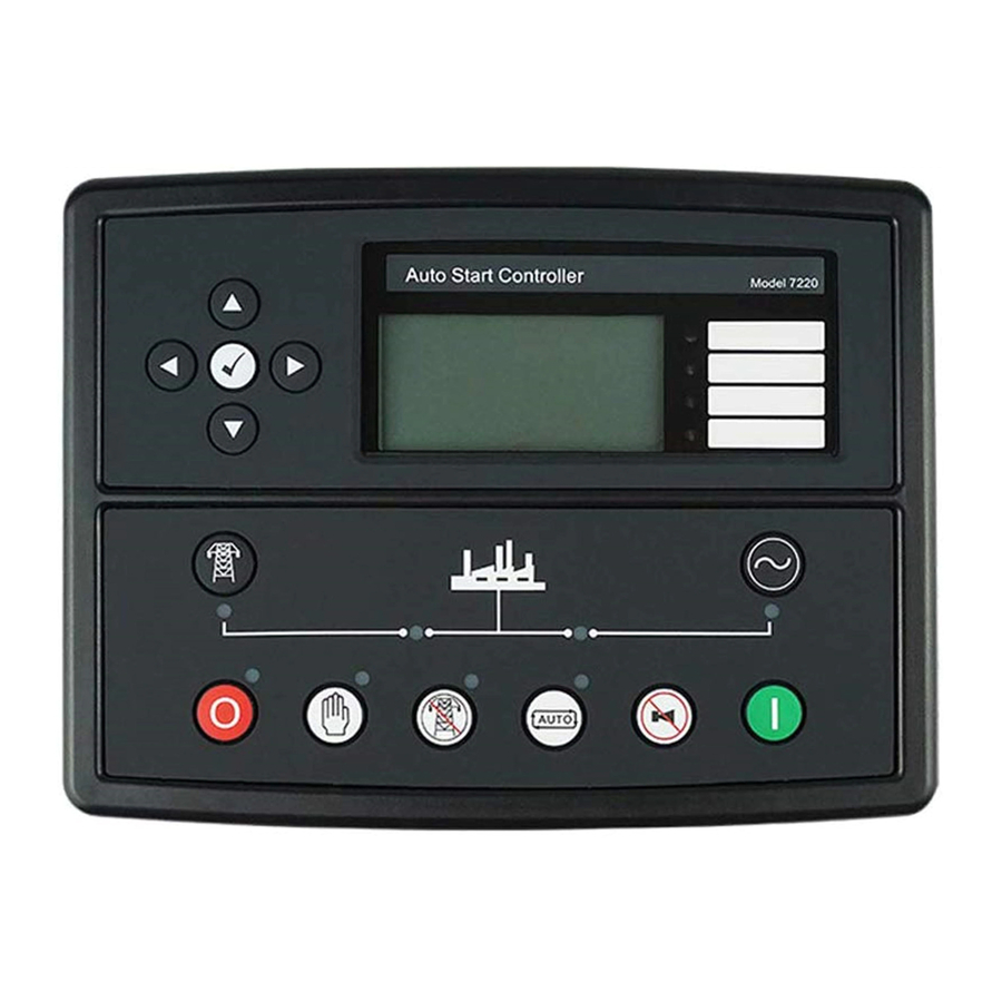
Page 58: Description Of Controls
DSE7200 / 7300 Series Operators Manual 5 DESCRIPTION OF CONTROLS The following section details the function and meaning of the various controls on the module. 5.1 DSE7210 / DSE7310 AUTOSTART CONTROL MODULE Main status and instrumentation display Menu navigation Four configurable... - Page 59 DSE7200 / 7300 Series Operators Manual Generator Available LED. On when the Close Generator LED. generator is within limits On When the Generator and able to Breaker closes / take load. generator is on load NOTE:- “Generator on load” LED has two modes of operation depending upon the configuration of the controllers digital inputs.
-
Page 60: Dse7220 / Dse7320 Amf Control Module
DSE7200 / 7300 Series Operators Manual 5.2 DSE7220 / DSE7320 AMF CONTROL MODULE Main status and instrumentation display Menu navigation Four configurable buttons LEDs Transfer to generator (manual mode Transfer to only) mains (manual mode only) Start engine (when in manual mode) Select Stop mode... - Page 61 DSE7200 / 7300 Series Operators Manual Mains Available LED. On when the mains is within limits and able to take load. Generator Available LED. On when the Close Mains LED. Close Generator LED. generator is On When The Generator On When The Generator within limits Is Required To Be On Is Required To Be On...
-
Page 62: Quickstart Guide
DSE7200 / 7300 Series Operators Manual 5.3 QUICKSTART GUIDE This section provides a quick start guide to the module’s operation. 5.3.1 STARTING THE ENGINE First, select manual mode then press the Start button to crank the engine. NOTE:- For further details, see the section entitled ‘OPERATION’ elsewhere in this manual. 5.3.2 STOPPING THE ENGINE Select Stop/Reset mode. -
Page 63: Viewing The Instrument
If no buttons are pressed upon entering an instrumentation page, the instruments will be displayed automatically subject to the setting of the LCD Scroll Timer. The LCD Page and LCD Scroll timers are configurable using the DSE Configuration Suite Software or by using the Front Panel Editor. -
Page 64: Status
Factory setting of Status screen showing engine stopped...and engine running. The contents of this display may vary depending upon configuration by the generator manufacturer / supplier. The display above was achieved with the factory settings, shown below in the DSE Configuration suite software: ‘Stop Mode’ etc is... -
Page 65: Engine
Engine ECU Link* *When connected to suitably configured and compatible engine ECU. For details of supported engines see ‘Electronic Engines and DSE wiring’ (DSE Part number 057-004). Depending upon configuration and instrument function, some of the instrumentation items may include a tick icon beside them. -
Page 66: Generator
DSE7200 / 7300 Series Operators Manual 5.4.3 GENERATOR Contains electrical values of the generator (alternator), measured or derived from the module’s voltage and current inputs. • Generator Voltage (ph-N) • Generator Voltage (ph-ph) • Generator Frequency • Generator Current • Generator Earth Current •... -
Page 67: Mains (Dse7220/Dse7320 Only)
DSE7200 / 7300 Series Operators Manual 5.4.4 MAINS (DSE7220/DSE7320 ONLY) Contains electrical values of the mains (utility) supply, measured or derived from the module’s mains voltage and current (where applicable) inputs. • Mains Voltage (ph-N) • Mains Voltage (ph-ph) • Mains Current (if the CT location is in the ‘load’... - Page 68 DSE7200 / 7300 Series Operators Manual Example 1 continued – Modem diagnostics NOTE:- Modem diagnostic screens are available on 7300 module versions 5 and above only. The modem screens appear only when the module has been configured for use with a modem. Modem diagnostic screens are included;...
- Page 69 If the GSM modem is not purchased from DSE, ensure that it has been correctly set to operate at 9600 baud. You may need to install a terminal program on your PC and consult your modem supplier to do this. GSM modems...
- Page 70 The factory settings are for the module to communicate at 19200 baud, modbus slave address 10. To use the RS485 port, ensure that ‘port usage’ is correctly set using the DSE Configuration Suite Software. Required settings are shown below.
-
Page 71: About
DSE7200 / 7300 Series Operators Manual 5.4.6 ABOUT Contains important information about the module and the firmware versions. This information may be asked for when contacting DSE Technical Support Department for advice. • Variant (ie 7210, 7220, 7310, 7320) About •... -
Page 72: Can Error Messages
ECU Warning Type of alarm that is triggered in the Warning DSE module (ie Warning or Shutdown) Press to access the list of current active Engine DTCs (Diagnostic Trouble Codes). The code interpreted by the module shows on the display as a text message. -
Page 73: Viewing The Event Log
7300 series log is capable of storing the last 250 log entries. Under default factory settings, the event log only includes shutdown and electrical trip alarms logged (The event log does not contain Warning alarms), however this is configurable by the system designer using the DSE Configuration Suite software. -
Page 74: User Configurable Indicators
DSE7200 / 7300 Series Operators Manual 5.6 USER CONFIGURABLE INDICATORS These LEDs can be configured by the user to indicate any one of 100+ different functions based around the following:- • Indications - Monitoring of a digital input and indicating associated functioning user’s equipment - Such as Battery Charger On or Louver’s Open, etc. -
Page 75: Controls
DSE7200 / 7300 Series Operators Manual 5.7 CONTROLS Stop / Reset This button places the module into its Stop/Reset mode. This will clear any alarm conditions for which the triggering criteria have been removed. If the engine is running and the module is in Stop mode, the module will automatically instruct the changeover device to unload the generator (‘Close Generator’... - Page 76 If generator is on load, opens the generator breaker • If generator and mains are off load, closes the generator breaker. Open generator (DSE7210/DSE7310 only) Allows the operator to open the generator (when in Manual mode only) Transfer to mains Operative in Manual Mode only ‘Normal’...
-
Page 77: Operation (Standalone)
DSE7200 / 7300 Series Operators Manual 6 OPERATION (STANDALONE) The following description details the sequences followed by a module containing the standard ‘factory configuration’. Remember that if you have purchased a completed generator set or control panel from your supplier, the module’s configuration will probably have been changed by them to suit their particular requirements. -
Page 78: Dummy Load / Load Shedding Control
If the loading remains at these levels after the completion of the timer, the ‘highest’ active Dummy Load Control output is de-energised. This continues until all Dummy Load Control outputs have been de-energised. Example screen shot of Dummy Load Control setup in the DSE Configuration Suite... -
Page 79: Load Shedding Control
When the set enters a stopping sequence for any reason the Load Shedding control’ outputs will de-energise at the same time as the generator load switch is signalled to open. Example screen shot of Load Shedding Control setup in the DSE Configuration Suite... -
Page 80: Sms Control
SMS message and leave the module in the AUTO position 0123 3 SMS Message 4 This SMS message will place the module into the STOP position. 0123 4 Example screen shot of SMS Control setup in the DSE Configuration Suite 6.4 STOP MODE... - Page 81 Oil pressure switch must be closed to indicate low oil pressure (MPU version only) When the engine has stopped, it is possible to send configuration files to the module from DSE Configuration Suite PC software and to enter the Front Panel Editor to change parameters.
-
Page 82: Ecu Override
As the ECU is usually unpowered when the engine is not running, it must be turned on manually as follows : • Select STOP mode on the DSE controller. • Press and hold the START button to power the ECU. As the controller is in STOP mode, the engine will not be started. -
Page 83: Automatic Mode
DSE7200 / 7300 Series Operators Manual 6.5 AUTOMATIC MODE NOTE:- If a digital input configured to panel lock is active, changing module modes will not be possible. Viewing the instruments and event logs is NOT affected by panel lock. Activate auto mode be pressing the pushbutton. -
Page 84: Engine Running
(depending upon configuration) add dummy loads or remove non-essential loads. This is configured as part of the Load Shedding and Dummy Load control settings in the DSE Configuration Suite Software. See section entitled Dummy Load / Load Shedding elsewhere in this document for further details. -
Page 85: Manual Mode
DSE7200 / 7300 Series Operators Manual 6.6 MANUAL MODE NOTE:- If a digital input configured to panel lock is active, changing module modes will not be possible. Viewing the instruments and event logs is NOT affected by panel lock. Activate Manual mode be pressing the pushbutton. -
Page 86: Engine Running
• Press the transfer to mains button (DSE7220/DSE7320 only) • Press the Open Generator button (DSE7210/DSE7310 only) • Press the auto mode button to return to automatic mode. For further details of breaker control, see the section entitled “controls and indications” elsewhere in this manual. -
Page 87: Stopping Sequence
DSE7200 / 7300 Series Operators Manual 6.6.6 STOPPING SEQUENCE In manual mode the set will continue to run until either : • The stop button is pressed – The set will stop immediately or after off load cooling run depending upon configuration. -
Page 88: Test Mode
DSE7200 / 7300 Series Operators Manual 6.7 TEST MODE NOTE:- Test Mode is only applicable to DSE7220/DSE7320 controllers. NOTE:- If a digital input configured to panel lock is active, changing module modes will not be possible. Viewing the instruments and event logs is NOT affected by panel lock. Activate test mode be pressing the pushbutton. -
Page 89: Engine Running
DSE7200 / 7300 Series Operators Manual 6.7.3 ENGINE RUNNING Once the engine is running, the Warm Up timer, if selected, begins, allowing the engine to stabilise before accepting the load. Load will be automatically transferred from the mains supply to the generator. NOTE:-The load transfer signal remains inactive until the Oil Pressure has risen. -
Page 90: Operation (Dual Mutual Standby)
Always refer to your configuration source for the exact sequences and timers observed by any particular module in the field. Screen shot from DSE Configuration Suite PC Software showing the configuration of the Master and Slave controllers. Dual Mutual Standby will allow the generators to operate fully automatically, starting and stopping as required with no user intervention, with the master backed up by the slave. -
Page 91: Protections
DSE7200 / 7300 Series Operators Manual 8 PROTECTIONS When an alarm is present, the Audible Alarm will sound and the Common alarm LED if configured will illuminate. The audible alarm can be silenced by pressing the Mute button The LCD display will jump from the ‘Information page’ to display the Alarm Page Number of present alarms. -
Page 92: Protections Disabled
The system designer provides this switch (not DSE) so its location will vary depending upon manufacturer, however it normally takes the form of a key operated switch to prevent inadvertent activation. Depending upon configuration, a warning alarm may be generated when the switch is operated. -
Page 93: Can Alarms
DSE7200 / 7300 Series Operators Manual 8.1.3 CAN ALARMS NOTE:- Please refer to the engine manufacturer’s documentation for Can error message information. CAN alarms are messages sent from the CAN ECU to the DSE controller and displayed as follows in the below tables. Display... -
Page 94: Indications
DSE7200 / 7300 Series Operators Manual 8.2 INDICATIONS Indications are non-critical and often status conditions. They do not appear on the LCD of the module as a text message. However an output or LED indicator can be configured to draw the operators attention to the event. Example •... -
Page 95: Warnings
DSE7200 / 7300 Series Operators Manual 8.3 WARNINGS Warnings are non-critical alarm conditions and do not affect the operation of the generator system, they serve to draw the operators attention to an undesirable condition. Example Alarm Charge Failure Warning In the event of an alarm the LCD will jump to the alarms page, and scroll through all active warnings and shutdowns. -
Page 96: High Current Warning Alarm
This is ‘logged’ by the module to allow DSE Technical Staff to check if the protections have been disabled on the module at any time. This feature is available from V4 onwards. -
Page 97: Shutdowns
DSE7200 / 7300 Series Operators Manual 8.5 SHUTDOWNS NOTE:- Shutdown and Electrical Trip alarms can be disabled by user configuration. See the section entitled Protections Disabled elsewhere in this document. Shutdowns are latching alarms and stop the Generator. Clear the alarm and remove the fault then press Stop/Reset to reset the module. - Page 98 Can datalink, the engine shuts down. ECU SHUTDOWN The engine ECU has detected a shutdown alarm and has informed the DSE module of this situation. The exact error is also indicated on the module’s display. kW OVERLOAD The measured Total kW is above the setting of the kW overload...
-
Page 99: Electrical Trips
This is ‘logged’ by the module to allow DSE Technical Staff to check if the protections have been disabled on the module at any time. This feature is available from V4 onwards. -
Page 100: High Current Shutdown / Electrical Trip Alarm
DSE7200 / 7300 Series Operators Manual 8.7 HIGH CURRENT SHUTDOWN / ELECTRICAL TRIP ALARM The overcurrent alarm combines a simple warning trip level with a fully functioning IDMT curve for thermal protection. 8.7.1 IMMEDIATE WARNING If the Immediate Warning is enabled, the controller generates a warning alarm as soon as the Trip level is reached. The alarm automatically resets once the generator loading current falls below the Trip level (unless All Warnings are latched is enabled). - Page 101 DSE7200 / 7300 Series Operators Manual Factory settings for the IDMT Alarm when used on a brushless alternator are as follows (screen capture from the DSE Configuration Suite PC software : (Trip setting value) (time multiplier) These settings provide for normal running of the generator up to 100% full load. If full load is surpassed, the Immediate Warning alarm is triggered, the set continues to run.
- Page 102 DSE7200 / 7300 Series Operators Manual...
-
Page 103: Earth Fault Shutdown / Electrical Trip Alarm
I is the actual earth current measured (Trip setting value) is the trip setting value K (time multiplier setting) The settings shown in the example above are a screen capture of the DSE factory settings, taken from the DSE Configuration Suite software. -
Page 104: Short Circuit Alarm
I is the actual current measured (Trip setting Is is the trip setting value value) K (time multiplier setting) The settings shown in the example above are a screen capture of the DSE factory settings, taken from the DSE Configuration Suite software. -
Page 105: Maintenance Alarm
Activating a input that has been configured to maintenance x reset, where x is the number of the maintenance alarm (1 to 3). • Pressing the maintenance reset button in the DSE Configuration Suite, Maintenance section. • Pressing and holding the stop button when the module’s display is on the maintenance alarm section. -
Page 106: Scheduler
DSE7200 / 7300 Series Operators Manual Example 4 Screen capture from DSE Configuration Suite Software showing the configuration holding stop button to reset the maintenance alarm. 8.11 SCHEDULER DSE7000 Series contains an inbuilt exercise run scheduler, capable of automatically starting and stopping the set. -
Page 107: Front Panel Configuration
DSE7200 / 7300 Series Operators Manual 8.12 FRONT PANEL CONFIGURATION This configuration mode allows the operator limited customising of the way the module operates. Use the module’s navigation buttons to traverse the menu and make value changes to the parameters: Increase value / next item Previous page Next page... -
Page 108: Accessing The Main Front Panel Configuration Editor
: NOTE: The PIN number is not set by DSE when the module leaves the factory. If the module has a PIN code set, this has been affected by your generator supplier who should be contacted if you require the code. -
Page 109: Editing A Parameter
DSE7200 / 7300 Series Operators Manual 8.13.1 EDITING A PARAMETER Enter the editor as described above. Press the (left) or (right) buttons to cycle to the section you wish to view/change. Press the (up or down) buttons to select the parameter you wish to view/change within the currently selected section. -
Page 110: Adjustable Parameters
DSE7200 / 7300 Series Operators Manual 8.13.2 ADJUSTABLE PARAMETERS Front Panel Configuration Editor = Only available on DSE7220 / DSE7320 AMF Modules Section Parameter as shown on display Settings DISPLAY Contrast Language English 0h 0m 0s LCD Page Timer Auto Scroll Delay 0h 0m 0s Current Date and time hh:mm... - Page 111 DSE7200 / 7300 Series Operators Manual Front Panel Configuration Editor (continued) Section Parameter as shown on display Settings MAINS Mains Transient Delay 0m 0s Return Delay Oh 0m 0s 0m 0.0s Mains Transfer Time TIMERS LCD Page Timer 0h 0m 0s Auto Scroll Delay 0h 0m 0s Pre Heat Timer...
-
Page 112: Accessing The 'Running' Configuration Editor
DSE7200 / 7300 Series Operators Manual 8.14 ACCESSING THE ‘RUNNING’ CONFIGURATION EDITOR The ‘running’ editor can be entered while the engine is running. All protections remain active if the engine is running while the running editor is entered. Press and hold the button to enter the running editor. -
Page 113: Commissioning
DSE7200 / 7300 Series Operators Manual 9 COMMISSIONING 9.1.1 PRE-COMMISSIONING Before the system is started, it is recommended that the following checks are made:- 10.1. The unit is adequately cooled and all the wiring to the module is of a standard and rating compatible with the system. -
Page 114: Fault Finding
DSE7200 / 7300 Series Operators Manual 10 FAULT FINDING SYMPTOM POSSIBLE REMEDY Unit is inoperative Check the battery and wiring to the unit. Check the DC supply. Check the DC fuse. Read/Write configuration does not operate Unit shuts down Check DC supply voltage is not above 35 Volts or below 9 Volts Check the operating temperature is not above 70°C. - Page 115 DSE7200 / 7300 Series Operators Manual SYMPTOM POSSIBLE REMEDY Incorrect reading on Engine Check engine is operating correctly. Check sensor and wiring paying gauges particular attention to the wiring to terminal 47 (refer to appendix). Check that sensor is compatible with the 7000 series module and that the module Fail to stop alarm when engine is configuration is suited to the sensor.
-
Page 116: Maintenance, Spares, Repair And Servicing
In the case of malfunction, you should contact your original equipment supplier (OEM). 11.1 PURCHASING ADDITIONAL CONNECTOR PLUGS FROM DSE 11.1.1 DSE7200 SERIES If you require additional plugs from DSE, please contact our Sales department using the part numbers below. 11.1.1.1 PACK OF PLUGS Module type... -
Page 117: Dse7300 Series
DSE7200 / 7300 Series Operators Manual 11.1.2 DSE7300 SERIES If you require additional plugs from DSE, please contact our Sales department using the part numbers below. 11.1.2.1 PACK OF PLUGS Module type Plug Pack Part Number DSE7310 057-513 DSE7320 007-514 11.1.2.2 INDIVIDUAL PLUGS... -
Page 118: Expansion Modules
NOTE:- DSENet® utilises an RS485 connection. Using Belden 9841 (or equivalent) cable allows for the expansion cable to be extended to a maximum of 1.2km. DSE Stock and supply Belden 9841 cable. DSE Part Number 016-030. DSE Part numbers Max No. -
Page 119: Ethernet (Lan) Connection
DSE7200 / 7300 Series Operators Manual 11.5 ETHERNET (LAN) CONNECTION NOTE:- DSE860 and DSE865 cannot be used with the DSE7210 or DSE7220 control modules. Sales Model order Operator Installation Item Description literatur number manual Instructions Model DSE860 RS232 to Ethernet Adaptor. -
Page 120: Warranty
DSE7200 / 7300 Series Operators Manual 12 WARRANTY DSE provides limited warranty to the equipment purchaser at the point of sale. For full details of any applicable warranty, you are referred to your original equipment supplier (OEM). 13 DISPOSAL 13.1 WEEE (WASTE ELECTRICAL AND ELECTRONIC EQUIPMENT) - Page 121 This page is intentionally blank.
- Page 122 This page is intentionally blank...
- Page 123 ® DSEGenset DSE7210/20 AUTO START & AUTO MAINS FAILURE CONTROL MODULES CONFIGURABLE DC OUTPUTS ANALOGUE EMERGENCY DC POWER PORT INPUTS SENDERS STOP SUPPLY 8-35V DSE7210/20 DEUTZ ISUZU PERKINS CATERPILLAR VOLVO CUMMINS OTHER SCANIA MAINS (UTILITY) N/C VOLT FREE N/O VOLT...
- Page 124 FEATURES ELECTRICAL SAFETY BS EN 60950 Safety of Information Technology Equipment, including Electrical Business Equipment The DSE7210 is an Auto Start Both modules are compatible with The modules can be easily TEMPERATURE BS EN 60068-2-1 Control Module and the DSE7220 is...
- Page 125 Configurable event log (100) • True dual mutual standby with load • PLC editor allows user DIMENSIONS • Tier 4 CAN engine support balancing timer (DSE7210 only) configurable functions to meet OVERALL • Integral PLC editor • USB connectivity specific application 240 mm x 181 mm x 42 mm 9.4”...
- Page 126 053-026 TYPICAL WIRING DIAGRAM D E E P S E A E L E C T R O N I C S ISSUE 8 7 2 1 0 I N S T A L L A T I O N I N S T R U C T I O N S ACCESSING THE FRONT PANEL CONFIGURATION EDITOR •...
- Page 127 Front Panel Configuration Editor (continued) ADJUSTABLE PARAMETERS (Configuration editor) Section Parameter as shown on display Factory Settings Section Parameter as shown on display Factory Settings TIMERS LCD Page Timer 0h 0m 0s DISPLAY Contrast Auto Scroll Delay 0h 0m 0s Language English Pre Heat Timer...
- Page 128 ® DSECONTROL Guía de Utilización Rápida DSE7000 057-101 Autor: John Ruddock...
- Page 129 Los pedidos de autorización por escrito al titular del derecho autoral para reproducción de cualquier parte de esta publicación debe ser enviada a Deep Sea Electronics Plc, en la dirección arriba. El logotipo de DSE y los nombres DSEUltra, DSEControl, DSEPower, DSEExtra, DSEMarine y DSENet son marcas registradas en el Reino Unido por Deep Sea Electronics PLC Cualquier referencia a nombres de productos de marca registrada utilizados en esta publicación es de propiedad...
- Page 130 2 ......................INTRODUCCIÓN 3 ................. DESCRIPCIÓN DE LOS CONTROLES MÓDULO DE CONTROL AUTOSTART DSE7210 / DSE7310 ........... 5 MÓDULO DE CONTROL AMF DSE7220 / DSE7320 ............... 7 Parte No. 057-101 Guía de Partida Rápida de la Série 7000 VERSIÓN 1 10/06/2011 JR...
- Page 131 Guía de Utilización Rápida del Modelo DSE Serie 7000 GUÍA DE PARTIDA RÁPIDA ....................9 3.3.1 PARTIDA EN EL MOTOR ....................9 3.3.2 PARADA DEL MOTOR ....................9 VERIFICANDO LOS INSTRUMENTOS ................... 10 3.4.1 CONTENIDO DE LAS PÁGINAS DEL INSTRUMENTO ............. 11 3.4.2...
- Page 132 Guía de Utilización Rápida del Modelo DSE Serie 7000 BibliograFÍA Este documento si refiere y es referido por las siguientes publicaciones de DSE, que pueden ser adquiridas desde el sitio www.deepseaplc.com CÓDIGO DESCRIPCIÓN 053-026 7210 installation instructions 053-027 7220 installation instructions...
- Page 133 Guía de Utilización Rápida del Modelo DSE Serie 7000 El módulo de la serie DSE7000 es proyectado para permitir que el operador pueda partir y parar el generador y, si necesario, transferir la carga al generador sea manualmente (vía botones de operación acoplados) o automáticamente.
- Page 134 Guía de Utilización Rápida del Modelo DSE Serie 7000 DESCRIPCIÓN DE LOS CONTROLES LA SECCIÓN SIGUIENTE DETALLA LAS FUNCIONES Y EL SIGNIFICADO DE LAS VARIAS FUNCIONES DE CONTROL DE LOS MÓDULOS. MÓDULO DE CONTROL AUTOSTART DSE7210 / DSE7310 Pantalla principal de status e instrumentación...
- Page 135 Guía de Utilización Rápida del Modelo DSE Serie 7000 LED de Generador Disponible. Prendido cuando el generador está dentro de los límites y listo para recibir carga LED de Generador Cerrado. Prendido cuando el generador necesita estar con carga. Parte No. 057-101 Guía de Partida Rapida de la Série7000 VERSIÓN 1 10/06/2011 JR...
- Page 136 Guía de Utilización Rápida del Modelo DSE Serie 7000 NOTA:- El LED de “Generador con carga” tiene dos modos de operación dependiendo de la configuración de las entradas digitales de los controladores: Entrada digital configurada para “auxiliar de generador cerrado” – El LED alumbra cuando la entrada auxiliar de generador cerrado esta activo –...
- Page 137 Guía de Utilización Rápida del Modelo DSE Serie 7000 módulo de control AMF DSE7220 / DSE7320 Pantalla principal de status e Cuatro LEDs instrumentación Botones de configurables navegación del menumenú Transferencia para el generador Transferencia (solo en modo para la red...
- Page 138 Guía de Utilización Rápida del Modelo DSE Serie 7000 LED de Red Disponible. Prendido cuando la red está dentro de los límites y lista para recibir carga GeneratorLED Generador Disponible Prendido cuando el LED de Generador LED de Red Cerrada.
- Page 139 Guía de Utilización Rápida del Modelo DSE Serie 7000 1) Entrada digital configurada para “auxiliar de red cerrado”– El LED alumbra cuando la entrada auxiliar de red cerrado esta activa – El LED muestra el estado del contacto auxiliar. 2) NO hay entrada configurada para “auxiliar de red cerrado” (configuración de fábrica) – El LED alumbra cuando el 7x20 provee la señal de carga a la red –...
-
Page 140: Guía De Partida Rápida
Guía de Utilización Rápida del Modelo DSE Serie 7000 GUÍA DE PARTIDA RÁPIDA Esta sección proporciona una guía rápida para operación de los módulos. 3.3.1 PARTIDA DEL MOTOR PrimeiroPrimero, seleccione el modo …entonces pulse el botón Partida para que el motor arranque. - Page 141 Guía de Utilización Rápida del Modelo DSE Serie 7000 Seleccione el modo Stop/Reset. El generador para. NOTA:- Para detalles adicionales, vea la sección “OPERACIÓN” en esto manual. Parte No. 057-101 Guía de Partida Rapida de la Série7000 VERSIÓN 1 10/06/2011 JR...
- Page 142 Guía de Utilización Rápida del Modelo DSE Serie 7000 VISUALIZANDO Los instrumentos É posible navegar por las diferentes páginas de información de la pantalla operando repetidas veces el botón de próxima página Una vez seleccionada, la página será mantenida en la pantalla LCD hasta que el usuario seleccione una página diferente o que el tiempo de inactividad sea expirado.
- Page 143 Guía de Utilización Rápida del Modelo DSE Serie 7000 Generador Pulse para cambiar a la próxima página - 3.4.1 CONTENIDO DE LA PAGINA DE INSTRUMENTOS Motor Velocidad del Motor • Presión de Aceite • Temperatura del Enfriador • Tensión de la Batería del Motor •...
- Page 144 • ECU Link del Motor* • *Cuando conectado a un motor ECU adecuadamente compatible y configurado. Para detalles sobre los motores suportados, vea ‘Motores Electrónicos y Cableado DSE’ (DSE Parte numero 057-004) Generador Tensión del Generador (ph-N) • Tensión del Generador (ph-ph) •...
- Page 145 Guía de Utilización Rápida del Modelo DSE Serie 7000 Tensión de la Red (ph-N) • Tensión de la Red (ph-ph) • Frecuencia de la Red • Sobre Tipo del Module • Versión de la Aplicación • USB ID – identificador propio para la conexión PC USB •...
-
Page 146: Mensajes De Error De La Can
Guía de Utilización Rápida del Modelo DSE Serie 7000 3.4.2 meNsaJes DE ERROR DE LA Can Cuando conectado a un motor CAN adecuado, el controlador serie 7000 muestra mensajes del estado de las alarmas desde el ECU. Tipo de alarma reportada por la ECU... -
Page 147: Verificando El Registro De Eventos
Guía de Utilización Rápida del Modelo DSE Serie 7000 VERIFICANDO EL REGISTRO DE EVENTOS (EVENT LOG) Event log 1/50 Número de alarmas presentes. Este es el evento 1 de un total de 50 eventos registrados. Presión de Aceite Baja Desligar... -
Page 148: Indicadores Configurables Por El Usuário
Guía de Utilización Rápida del Modelo DSE Serie 7000 Pulse para bajo para ver la próxima alarma de desligamiento más reciente. Al continuar pulsando para bajo verá todas las alarmas pasadas, después de las cuales la pantalla muestreará las alarmas más recientes y el ciclo empieza nuevamente. - Page 149 Guía de Utilización Rápida del Modelo DSE Serie 7000 La siguiente descripción detalla las secuencias seguidas por un módulo que contiene la ‘configuración de fábrica’ padrón. Recuérdese que si usted adquirió un grupo generador completo o un panel de control de su suministrador, la configuración de módulo irá...
- Page 150 Guía de Utilización Rápida del Modelo DSE Serie 7000 Como la ECU normalmente está desligada cuando el m Como la ECU normalmente está desligada cuando el motor no está en operación, ella otor no está en operación, ella debe ser encendida manualmente de la siguiente forma:...
-
Page 151: Esperando En Modo Automatico
Guía de Utilización Rápida del Modelo DSE Serie 7000 NOTA:- Si la entrada configurada para bloquear el panel (panel lock) es activada, no será posible cambiar el modo de operación. La visualización de los instrumentos y eventos NO ES afectada. - Page 152 Guía de Utilización Rápida del Modelo DSE Serie 7000 Cuando el motor entra en operación, el motor de arranque es desacoplado. La medición de velocidad es configurada en la fábrica para ser derivada desde la frecuencia del alternador principal del generador, pero puede ser medido también por el pick-up magnético montado en el volante del motor (seleccionado por PC usando...
-
Page 153: Secuencia De Parada
Guía de Utilización Rápida del Modelo DSE Serie 7000 MOTOR emEN OPERACIÓN 4.1.3 Una vez que el motor esté en funcionamiento, en temporizador de calentamiento (Warm Up), si seleccionado, parte, permitiendo que el motor estabilícese antes de aceptar la carga. - Page 154 Guía de Utilización Rápida del Modelo DSE Serie 7000 Parte No. 057-101 Guía de Partida Rápida de la Série 7000 VERSIÓN 1 10/06/2011 JR...
-
Page 155: Operación Manual
Guía de Utilización Rápida del Modelo DSE Serie 7000 OPERACIÓN MANUAL NOTA:- Si la entrada configurada para bloquear el panel (panel lock) es activada, no será posible cambiar el modo de operación. La visualización de los instrumentos y eventos NO ES afectada. -
Page 156: Motor En Funcionamiento
Guía de Utilización Rápida del Modelo DSE Serie 7000 Cuando el motor entra en operación, el motor de arranque es desacoplado. La medición de velocidad es configurada en la fabricafábrica para ser derivada desde la frecuencia del alternador principal, pero puede ser medido también por el pick-up magnético montado en el volante del motor (seleccionado por PC usando software... -
Page 157: Secuencia De Parada
Guía de Utilización Rápida del Modelo DSE Serie 7000 Activación del calendario interno de partida se configurado para partidas con • carga. NOTE:- La señal de transferencia de carga se mantiene inactiva hasta que la presión del aceite aumente. Esta actitud evita el desgaste excesivo del motor. -
Page 158: Modo De Operación De Prueba
Guía de Utilización Rápida del Modelo DSE Serie 7000 MODO DE OPERACIÓN DE PRUEBA NOTA:-El Modo de Prueba solo es aplicable en los controles DSE7220/DSE7320. NOTA:- Si la entrada configurada para bloquear el panel (panel lock) es activada, no será posible cambiar el modo de operación. La visualización de los instrumentos y eventos NO ES afectada. - Page 159 Guía de Utilización Rápida del Modelo DSE Serie 7000 Cuando el motor entra en operación, el motor de arranque es desacoplado. La medición de velocidad es configurada en la fábrica para ser derivada desde la frecuencia del alternador, pero puede ser medido también por el pick-up magnético montado en el volante del motor (seleccionado por PC usando software de configuración de los módulos de la serie DSE7000).
- Page 160 Guía de Utilización Rápida del Modelo DSE Serie 7000 4.3.3 MOTOR EN FUNCIONAMIENTO Una vez que el motor está en operación, el temporizador de calentamiento, si seleccionado, empieza, permitiendo que el motor estabilícese antes de aceptar la carga. La carga será transferida automáticamente de la red para el generador.
Need help?
Do you have a question about the DSE7210 and is the answer not in the manual?
Questions and answers