DSE DSE8610 User Manual
Dse8600 series control module
Hide thumbs
Also See for DSE8610:
- Installation instructions manual (2 pages) ,
- Installation instructions (2 pages)
Table of Contents

Related Manuals for DSE DSE8610


Summary of Contents for DSE DSE8610
- Page 1 DEEP SEA ELECTRONICS PLC DSE8610 Control Module Document number 057-115 Author : Anthony Manton DSE8610 Operator Manual Issue 8 CALL US TODAY REQUEST A QUOTE SHOP ONLINE 1-888-POWER-58 parts@genpowerusa.com www.genpowerusa.com...
- Page 2 Applications for the copyright holder’s written permission to reproduce any part of this publication should be addressed to Deep Sea Electronics Plc at the address above. The DSE logo is a UK registered trademark of Deep Sea Electronics PLC. Any reference to trademarked product names used within this publication is owned by their respective companies.
-
Page 3: Table Of Contents
DSE8610 Control & Instrumentation System Operators Manual Indicates a procedure or practice, which could result in injury to personnel or loss of life if WARNING! not followed correctly. TABLE OF CONTENTS Section Page BIBLIOGRAPHY ....................7 INSTALLATION INSTRUCTIONS ................... 7 TRAINING GUIDES ...................... - Page 4 DSE8610 Control & Instrumentation System Operators Manual 3.13.2 CABLE TIE FIXING POINTS .................. 34 3.13.3 SILICON SEALING GASKET ................. 34 3.14 APPLICABLE STANDARDS ..................35 3.14.1 ENCLOSURE CLASSIFICATIONS ................. 36 IP CLASSIFICATIONS ...................... 36 NEMA CLASSIFICATIONS ....................37 INSTALLATION ..................... 38 TERMINAL DESCRIPTION...................
- Page 5 DSE8610 Control & Instrumentation System Operators Manual SMS CONTROL ......................80 STOP MODE ......................... 81 6.4.1 ECU OVERRIDE ....................82 AUTOMATIC MODE ..................... 83 6.5.1 WAITING IN AUTO MODE ..................83 6.5.2 STARTING SEQUENCE..................83 6.5.3 ENGINE RUNNING ....................84 6.5.4...
- Page 6 DSE8610 Control & Instrumentation System Operators Manual MAINTENANCE, SPARES, REPAIR AND SERVICING ......116 15.1 PURCHASING ADDITIONAL CONNECTOR PLUGS FROM DSE ......116 INDIVIDUAL PLUGS ....................... 116 15.2 PURCHASING ADDITIONAL FIXING CLIPS FROM DSE ........116 15.3 PURCHASING ADDITIONAL SEALING GASKET FROM DSE ....... 116 15.4...
-
Page 7: Bibliography
DSE8610 Control & Instrumentation System Operators Manual 1 BIBLIOGRAPHY This document refers to and is referred to by the following DSE publications which can be obtained from the DSE website www.deepseaplc.com 1.1 INSTALLATION INSTRUCTIONS Installation instructions are supplied with the product in the box and are intended as a ‘quick start’ guide only. - Page 8 DSE8610 Control & Instrumentation System Operators Manual 2 INTRODUCTION This document details the installation and operation requirements of the DSE8610 Series modules, part of the DSEPower® range of products. The manual forms part of the product and should be kept for the entire life of the product. If the product is passed or supplied to another party, ensure that this document is passed to them for reference purposes.
-
Page 9: Specifications
Specification 3 SPECIFICATIONS 3.1 PART NUMBERING 8610 Variant Product type Standard DSE 8610 product 8610 Autostart Module Hardware revision Initial module release Issolated Can Port At the time of this document production, there are no variants of this product. 3.1.1 SHORT NAMES... -
Page 10: Power Supply Requirements
10 way connector Maximum cable size 2.5mm² (AWG 10) NOTE: For purchasing additional connector plugs from DSE, please see the section entitled Maintenance, Spares, Repair and Servicing elsewhere in this document. 3.3 POWER SUPPLY REQUIREMENTS Minimum supply voltage... -
Page 11: Generator Current Sensing
3.5.1 VA RATING OF THE CTS The VA burden of the DSE8610 module on the CTs is 0.5VA. However depending upon the type and length of cabling between the CTs and the DSE8610 module, CTs with a greater VA rating than the module are required. -
Page 12: Ct Polarity
To test orientation, run the generator in island mode (not in parallel with any other supply) and load the generator to around 10% of the set rating. Ensure the DSE module shows positive kW for all three individual phase readings. -
Page 13: Inputs
Specification 3.6 INPUTS 3.6.1 DIGITAL INPUTS Number 11 configurable inputs Arrangement Contact between terminal and ground Low level threshold 2.1V minimum High level threshold 6.6V maximum Maximum input voltage +50V DC with respect to plant supply negative Minimum input voltage -24V DC with respect to plant supply negative Contact wetting current 7mA typical... -
Page 14: Analogue Flexible Input
Specification Flexible sensor Number Measurement type Resistance measurement by measuring voltage across sensor with a fixed current applied Arrangement Differential resistance measurement input Measurement current 10mA Full scale 480Ω Over range / fail 540Ω Resolution Accuracy ±2% of full scale resistance (±9.6Ω) excluding transducer error Max common mode ±2V voltage... -
Page 15: Charge Fail Input
Flywheel teeth 10 to 500 NOTE : DSE can supply a suitable magnetic pickup device, available in two body thread lengths : DSE Part number 020-012 - Magnetic Pickup probe 5/8 UNF 2½” thread length DSE Part number 020-013 - Magnetic Pickup probe 5/8 UNF 4” thread length Magnetic Pickup devices can often be ‘shared’... -
Page 16: Outputs
Specification 3.7 OUTPUTS Ten (10) digital outputs are fitted to the DSE8610 controller. Additional outputs are provided for by adding up to ten (10) external relay boards (DSE2157). This allows for up to 80 additional digital outputs. 3.7.1 OUTPUTS A & B Type Normally used for Fuel / Start outputs. -
Page 17: Opening Coils / Shunt Trip Coils
For momentary (pulsed) closing signals, use OUTPUT D, the normally open relay: Generator When the DSE module requires the breaker closed, the output energises (closing the internal relay) for the period of the Breaker Close Pulse timer after which the output is de-energised (opening the internal relay). -
Page 18: Communication Ports
DSE8600 series to access these engine parameters with no physical connection to the sensor device. NOTE:- For further details for connections to CAN enabled engines and the functions available with each engine type, refer to the manual Electronic Engines and DSE Wiring. Part No. 057-004 CALL US TODAY... -
Page 19: Usb Connection
The USB port is provided to give a simple means of connection between a PC and the DSE8600 series controller. Using the DSE Configuration Suite Software, the operator is then able to control the module, starting or stopping the generator, selecting operating modes, etc. -
Page 20: Rs232
GSM modem for more remote communications. Many PCs are not fitted with an internal RS232 serial port. DSE DOES NOT recommend the use of USB to RS232 convertors but can recommend PC add-ons to provide the computer with an RS232 port. - Page 21 • designated mobile phones upon status and alarm conditions. For a data connection to a PC running DSE Configuration Suite Software, a ‘special’ CSD (Circuit • Switched Data) SIM card is required that will enable the modem to answer an incoming data call. Many ‘pay as you go’...
-
Page 22: Rs485
One advantage of the RS485 interface is the large distance specification (1.2km when using Belden 9841 (or equivalent) cable. This allows for a large distance between the DSE8600 series module and a PC running the DSE Configuration Suite software. The operator is then able to control the module, starting or stopping the generator, selecting operating modes, etc. -
Page 23: Msc
Specification 3.9.6 MSC The MSC (Multi System control) is used to communicate with other DSE modules in a system. The MSC is used for point-to-point cable connection of more than one device (maximum 32 Generator controller and another 8 Mains / Bus tie devices giving a maximum of 40 units) The maximum distance is 250M using Belden 9841, 120ohm impedance screened twisted pair cable. -
Page 24: Ethernet
Specification 3.9.7 ETHERNET The DSE8610 is fitted with ETHERNET socket for connection to LAN (local area networks) Description Do not connect Do not connect Do not connect Do not connect DIRECT PC CONNECTION Requirements DSE8610 • Crossover Ethernet cable (see Below) •... -
Page 25: Connection To Basic Ethernet
NOTE:- This cable can be purchased from any good PC or IT store. CONNECTION TO BASIC ETHERNET Requirements DSE8610 • Ethernet cable (see below) • Working Ethernet (company or home network) • PC with Ethernet port and Windows Internet Explorer 6 or above, Firefox •... -
Page 26: Connection To Company Infrastructure Ethernet
NOTE:- DSE Stock a 2m (2yds) Ethernet Cable – Part number 016-137. Alternatively they can be purchased from any good PC or IT store. CONNECTION TO COMPANY INFRASTRUCTURE ETHERNET Requirements DSE8610 •... -
Page 27: Connection To The Internet
NOTE:- DSE Stock a 2m (2yds) Ethernet Cable – Part number 016-137. Alternatively they can be purchased from any good PC or IT store. CONNECTION TO THE INTERNET Requirements •... - Page 28 NOTE:- DSE Stock a 2m (2yds) Ethernet Cable – Part number 016-137. Alternatively they can be purchased from any good PC or IT store. CALL US TODAY REQUEST A QUOTE SHOP ONLINE 1-888-POWER-58 parts@genpowerusa.com...
- Page 29 As modem/routers differ enormously in their configuration, it is not possible for DSE to give a complete guide to their use with the DSE8610. However it is possible to give a description of the requirements in generic terms. For details of how to achieve the connection to your modem/router you are referred to the supplier of your modem/router equipment.
-
Page 30: Dsenet® For Expansion Modules
While this is a very useful feature in some applications, the obvious drawback is that the DSENet® interface is no longer available for connection to expansion devices. Example of configuring the DSENet® for connection to Cummins QST GCS using the DSE Configuration Suite Software:... -
Page 31: Sounder
3.11.1 ADDING AN EXTERNAL SOUNDER TO THE APPLICATION Should an external alarm or indicator be required, this can be achieved by using the DSE Configuration Suite PC software to configure an auxiliary output for “Audible Alarm”, and by configuring an auxiliary input for “Alarm Mute”... -
Page 32: Dimensions And Mounting
Specification 3.13 DIMENSIONS AND MOUNTING DIMENSIONS 240.0mm x 181.1mm x 41.7mm (9.4” x 7.1” x 1.6”) PANEL CUTOUT 220mm x 160mm (8.7” x 6.3”) WEIGHT 0.7kg (1.4lb) CALL US TODAY REQUEST A QUOTE SHOP ONLINE 1-888-POWER-58 parts@genpowerusa.com www.genpowerusa.com... -
Page 33: Fixing Clips
Specification 3.13.1 FIXING CLIPS Supplied fixing clips hold the module into the panel fascia. Withdraw the fixing clip screw (turn anticlockwise) until only the pointed end is protruding from the clip. • Insert the three ‘prongs’ of the fixing clip into the slots in the side of the 8600 series module case. •... -
Page 34: Cable Tie Fixing Points
Specification 3.13.2 CABLE TIE FIXING POINTS Integral cable tie fixing points are included on the rear of the module’s case to aid wiring. This additionally provides strain relief to the cable loom by removing the weight of the loom from the screw connectors, thus reducing the chance of future connection failures. -
Page 35: Applicable Standards
Specification 3.14 APPLICABLE STANDARDS This document conforms to BS4884-1 1992 Specification for presentation of BS 4884-1 essential information. BS 4884-2 This document conforms to BS4884-2 1993 Guide to content BS 4884-3 This document conforms to BS4884-3 1993 Guide to presentation BS EN 60068-2-1 -30°C (-22°F) (Minimum temperature) -
Page 36: Enclosure Classifications
Specification 3.14.1 ENCLOSURE CLASSIFICATIONS IP CLASSIFICATIONS 8600 series specification under BS EN 60529 Degrees of protection provided by enclosures IP65 (Front of module when module is installed into the control panel with the optional sealing gasket). IP42 (front of module when module is installed into the control panel WITHOUT being sealed to the panel) First Digit Second Digit Protection against contact and ingress of solid objects... -
Page 37: Nema Classifications
Specification NEMA CLASSIFICATIONS 8600 series NEMA Rating (Approximate) 12 (Front of module when module is installed into the control panel with the optional sealing gasket). 2 (front of module when module is installed into the control panel WITHOUT being sealed to the panel) NOTE: - There is no direct equivalence between IP / NEMA ratings. -
Page 38: Installation
NOTE:- Terminal 14 is not fitted to the DSE8600 series controller. NOTE:- When the module is configured for operation with an electronic engine, FUEL and START output requirements may be different. Refer to Electronic Engines and DSE Wiring for further information. DSE Part No. 057-004. -
Page 39: Analogue Sensors
Installation – Terminal Description 4.1.2 ANALOGUE SENSORS DESCRIPTION CABLE NOTES SIZE 0.5mm² Sensor Common Return Return feed for sensors AWG 20 0.5mm² Oil Pressure Input Connect to Oil pressure sensor AWG 20 0.5mm² Coolant Temperature Input Connect to Coolant Temperature sensor AWG 20 0.5mm²... -
Page 40: Magnetic Pickup, Can And Expansion
NOTE:- Screened 120Ω Ω Ω Ω impedance cable specified for use with CAN must be used for the CAN link and the Multiset comms (MSC) link. DSE stock and supply Belden cable 9841 which is a high quality 120Ω Ω Ω Ω impedance cable suitable for CAN use (DSE part number 016-030) NOTE:- When the module is configured for CAN operation, terminals 22, 23 &... -
Page 41: Load Switching And Generator Voltage Sensing
Installation – Terminal Description 4.1.4 LOAD SWITCHING AND GENERATOR VOLTAGE SENSING DESCRIPTION CABLE NOTES SIZE 1.0mm Normally configured to control load switching device Output relay C AWG 18 (Recommend 10A fuse) 1.0mm Normally configured to control load switching device Output relay C AWG 18 1.0mm Normally configured to control load switching device... -
Page 42: Generator Current Transformers
(I1,I2,I3) s1 is the secondary of the CT that connects to the DSE Module’s input for the CT measuring s2 is the secondary of the CT that should be commoned with the s2 connections of all the other CTs and connected to the CT common terminal of the DSE8600 series modules. - Page 43 Installation – Terminal Description Connection of CT s1 terminal DESCRIPTION CABLE NOTES SIZE 2.5mm² CT Secondary for Gen L1 Connect to s1 secondary of L1 monitoring CT AWG 13 2.5mm² CT Secondary for Gen L2 Connect to s1 secondary of L2 monitoring CT AWG 13 2.5mm²...
-
Page 44: Configurable Digital Inputs
Installation – Terminal Description 4.1.7 CONFIGURABLE DIGITAL INPUTS DESCRIPTION CABLE NOTES SIZE 0.5mm² Configurable digital input A Switch to negative AWG 20 0.5mm² Configurable digital input B Switch to negative AWG 20 0.5mm² Configurable digital input C Switch to negative AWG 20 0.5mm²... -
Page 45: Rs485 Connector
Installation – Terminal Description 4.1.9 RS485 CONNECTOR PIN No NOTES Two core screened twisted pair cable. 120Ω impedance suitable for RS485 use. Recommended cable type - Belden 9841 Max distance 1200m (1.2km) when using Belden 9841 or direct equivalent. Location of RS485 connector Location of RS232 connector 4.1.10 RS232 CONNECTOR... -
Page 46: Typical Wiring Diagrams
Genset manufacturers and panel builders may use these diagrams as a starting point; however, you are referred to the completed system diagram provided by your system manufacturer for complete wiring detail. Further wiring suggestions are available in the following DSE publications, available at www.deepseaplc.com website members. -
Page 47: Phase, 4 Wire With Restricted Earth Fault Protection
Installation – Typical Wiring Diagrams 4.2.1 3 PHASE, 4 WIRE WITH RESTRICTED EARTH FAULT PROTECTION NOTE: - Earthing the neutral conductor ‘before’ the neutral CT allows the module to read earth faults ‘after’ the CT only (Restricted to load / downstream of the CT) Earthing the neutral conductor ‘after’... -
Page 48: Phase, 4 Wire Without Earth Fault Protection
Installation – Typical Wiring Diagrams 4.2.2 3 PHASE, 4 WIRE WITHOUT EARTH FAULT PROTECTION CALL US TODAY REQUEST A QUOTE SHOP ONLINE 1-888-POWER-58 parts@genpowerusa.com www.genpowerusa.com... -
Page 49: Phase 4 Wire With Unrestricted Earth Fault Protection
Installation – Typical Wiring Diagrams 4.2.3 3 PHASE 4 WIRE WITH UNRESTRICTED EARTH FAULT PROTECTION NOTE:- Unrestricted Earth Fault Protection detects earth faults in the load and in the generator. Be sure to measure the natural earth fault of the site before deciding upon an earth fault alarm trip level. CALL US TODAY REQUEST A QUOTE SHOP ONLINE... -
Page 50: Earth Systems
Earth) Positive Earth When using a DSE module with a Positive Earth System (the battery positive connects to Earth), the following points must be followed: Follow the typical wiring diagram as normal for all sections EXCEPT the earth points •... -
Page 51: Alternative Topologies
Installation – Typical Wiring Diagrams 4.3 ALTERNATIVE TOPOLOGIES The DSE8610 controller is factory configured to connect to a 3 phase, 4 wire Star connected alternator. This section details connections for alternative AC topologies. Ensure to configure the DSE8610 controller to suit the required topology. -
Page 52: Single Phase Without Earth Fault
Installation – Typical Wiring Diagrams 4.3.2 SINGLE PHASE WITHOUT EARTH FAULT CALL US TODAY REQUEST A QUOTE SHOP ONLINE 1-888-POWER-58 parts@genpowerusa.com www.genpowerusa.com... -
Page 53: Phase (L1 & L2) 3 Wire With Restricted Earth Fault
Installation – Typical Wiring Diagrams 4.3.3 2 PHASE (L1 & L2) 3 WIRE WITH RESTRICTED EARTH FAULT NOTE:- Earthing the neutral conductor ‘before’ the neutral CT allows the module to read earth faults ‘after’ the CT only (Restricted to load / downstream of the CT) Earthing the neutral conductor ‘after’... -
Page 54: Phase (L1 & L2) 3 Wire Without Earth Fault
Installation – Typical Wiring Diagrams 4.3.4 2 PHASE (L1 & L2) 3 WIRE WITHOUT EARTH FAULT CALL US TODAY REQUEST A QUOTE SHOP ONLINE 1-888-POWER-58 parts@genpowerusa.com www.genpowerusa.com... -
Page 55: Phase (L1 & L3) 3 Wire With Restricted Earth Fault
Installation – Typical Wiring Diagrams 4.3.5 2 PHASE (L1 & L3) 3 WIRE WITH RESTRICTED EARTH FAULT NOTE:- Earthing the neutral conductor ‘before’ the neutral CT allows the module to read earth faults ‘after’ the CT only (Restricted to load / downstream of the CT) Earthing the neutral conductor ‘after’... -
Page 56: Phase (L1 & L3) 3 Wire Without Earth Fault Measuring
Installation – Typical Wiring Diagrams 4.3.6 2 PHASE (L1 & L3) 3 WIRE WITHOUT EARTH FAULT MEASURING CALL US TODAY REQUEST A QUOTE SHOP ONLINE 1-888-POWER-58 parts@genpowerusa.com www.genpowerusa.com... -
Page 57: Typical Arrangement Of Dsenet
Installation – Typical Wiring Diagrams 4.4 TYPICAL ARRANGEMENT OF DSENET® Twenty (20) devices can be connected to the DSENet®, made up of the following devices : Device Max number supported DSE2130 Input Expansion DSE2131 Input Expansion DSE2133 Input Expansion DSE2152 Output Expansion DSE2157 Output Expansion DSE2548 LED Expansion For part numbers of the expansion modules and their documentation, see section entitled DSENet Expansion... -
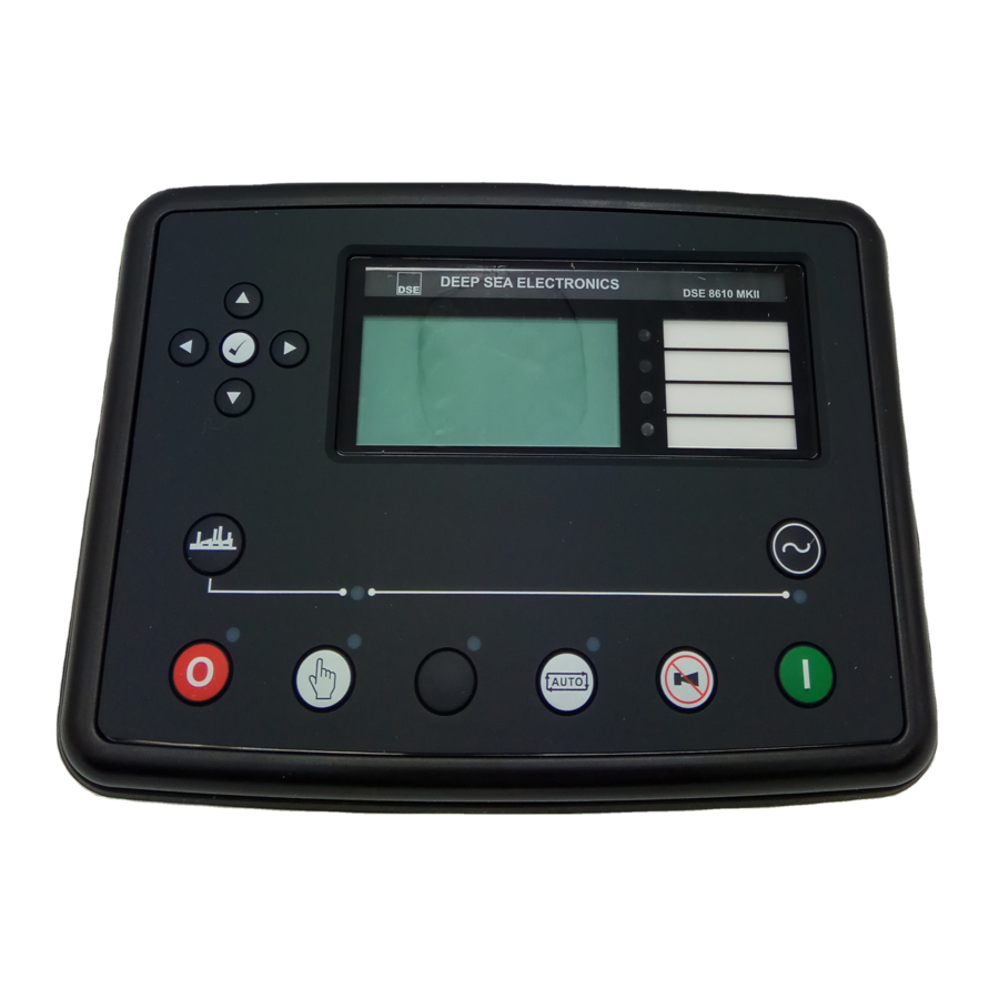
Page 58: Description Of Controls
Installation – Description Of Controls 5 DESCRIPTION OF CONTROLS The following section details the function and meaning of the various controls on the module. 5.1 DSE8610 AUTOSTART CONTROL MODULE Main status and instrumentation display Menu navigation Four configurable buttons LEDs... - Page 59 – The LED shows the state of the auxiliary contact. 2) There is NO input configured for “Generator closed auxiliary” (factory default setting) – The LED illuminates when the DSE8610 gives the loading signal to the generator – The LED shows the state of the DSE8610s loading request.
-
Page 60: Quickstart Guide
Installation – Description Of Controls 5.2 QUICKSTART GUIDE This section provides a quick start guide to the module’s operation. 5.2.1 STARTING THE ENGINE First, select manual mode then press the Start button to crank the engine. NOTE:- For further details, see the section entitled ‘OPERATION’ elsewhere in this manual. 5.2.2 STOPPING THE ENGINE Select Stop/Reset mode. -
Page 61: Viewing The Instrument
If no buttons are pressed upon entering an instrumentation page, the instruments will be displayed automatically subject to the setting of the LCD Scroll Timer. The LCD Page and LCD Scroll timers are configurable using the DSE Configuration Suite Software or by using the Front Panel Editor. -
Page 62: Status
0.0pf The contents of this display may vary depending upon configuration by the generator manufacturer / supplier. The display above is achieved with the factory settings, shown below in the DSE Configuration suite software: ‘Stop Mode’ etc is displayed on the... -
Page 63: Configurable Editor Screens
Viewing The Instrument Pages 5.3.2 CONFIGURABLE EDITOR SCREENS This is the “Editor” Page which can be configured in the “Advanced “, Section of the PC software. The “Editor” page can be seen once an item has been configured and written back to the module. Example –... -
Page 64: Engine
• *When connected to suitably configured and compatible engine ECU. For details of supported engines see ‘Electronic Engines and DSE wiring’ (DSE Part number 057-004). Depending upon configuration and instrument function, some of the instrumentation items may include a tick icon beside them. -
Page 65: Generator
Viewing The Instrument Pages 5.3.4 GENERATOR Contains electrical values of the generator (alternator), measured or derived from the module’s voltage and current inputs. Generator Voltage (ph-N) • Generator Voltage (ph-ph) • Generator Frequency • Generator Current • Generator Earth Current •... -
Page 66: Rs232 Serial Port
Example 1 – Module connected to an RS232 telephone modem. When the DSE8610 series module is power up, it will send ‘initialisation strings’ to the connected modem. It is important therefore that the modem is already powered, or is powered up at the same time as the DSE86xx series module. - Page 67 Viewing The Instrument Pages Example 1 continued – Modem diagnostics Modem diagnostic screens are included; press when viewing the RS232 Serial Port instrument to cycle the available screens. If you are experiencing modem communication problems, this information will aid troubleshooting. Shows the state of the modem communication lines.
- Page 68 ‘voice number’ and is often called Circuit Switched Data (CSD) by the SIM provider. If the GSM modem is not purchased from DSE, ensure that it has been correctly set to operate at 9600 baud. You may need to install a terminal program on your PC and consult your modem supplier to do this. GSM modems purchased from DSE are already configured to work with the DSE86xx series module.
-
Page 69: Rs485 Serial Port
2 seconds. The DSE Modbus Gencomm document containing register mappings inside the DSE module is available upon request from support@deepseaplc.com. Email your request along with the serial number of your DSE module to ensure the correct information is sent to you. -
Page 70: About
USB ID – unique identifier for PC USB connection • Analogue Measurements software version • Firmware Update Boot loader software version. • Ethernet Pages Update Network settings using DSE Configuration Suite Software+ 1 Power cycle off/on before the editor • pages are updated.. Network Network Network Network... -
Page 71: Data Logging Pages
Viewing The Instrument Pages Data Logging Pages The DSE data logging pages show information depending on the configuration in the module. Location of stored data. Data Logging Internal module memory or external Log to internal memory USB memory. Logging active... -
Page 72: Can Error Messages
Alarm ECU Warning Type of alarm that is triggered in the Warning DSE module (i.e. Warning or Shutdown) Press to access the list of current active Engine DTCs (Diagnostic Trouble Codes). The code interpreted by the module shows on the display as a text message. -
Page 73: Viewing The Event Log
86xx series log is capable of storing the last 250 log entries. Under default factory settings, the event log only includes shutdown and electrical trip alarms logged (The event log does not contain Warning alarms); however, this is configurable by the system designer using the DSE Configuration Suite software. -
Page 74: User Configurable Indicators
Controls and Indications 5.5 USER CONFIGURABLE INDICATORS These LEDs can be configured by the user to indicate any one of 100+ different functions based around the following:- • Indications - Monitoring of a digital input and indicating associated functioning user’s equipment - Such as Battery Charger On or Louvres Open, etc. -
Page 75: Controls
Controls and Indications 5.6 CONTROLS Stop / Reset This button places the module into its Stop/Reset mode. This will clear any alarm conditions for which the triggering criteria have been removed. If the engine is running and the module is in Stop mode, the module will automatically instruct the changeover device to unload the generator (‘Close Generator’... - Page 76 Transfer to generator Allows the operator to transfer the load to the generator, synchronising first if required. (when in Manual mode only) Open generator (DSE8610 only) Allows the operator to open the generator breaker (when in Manual mode only) Menu navigation Used for navigating the instrumentation, event log and configuration screens.
-
Page 77: Operation
Protections 6 OPERATION The following description details the sequences followed by a module containing the standard ‘factory configuration’. Remember that if you have purchased a completed generator set or control panel from your supplier, the module’s configuration will probably have been changed by them to suit their particular requirements. Always refer to your configuration source for the exact sequences and timers observed by any particular module in the field. -
Page 78: Dummy Load / Load Shedding Control
If the loading remains at these levels after the completion of the timer, the ‘highest’ active Dummy Load Control output is de-energised. This continues until all Dummy Load Control outputs have been de-energised. Example screen shot of Dummy Load Control setup in the DSE Configuration Suite CALL US TODAY... -
Page 79: Load Shedding Control
When the set enters a stopping sequence for any reason the Load Shedding control’ outputs will de-energise at the same time as the generator load switch is signalled to open. Example screen shot of Load Shedding Control setup in the DSE Configuration Suite CALL US TODAY... -
Page 80: Sms Control
SMS message and leave the module in the AUTO position SMS Message 4 This SMS message will place the module into the STOP position. 0123 4 Example screen shot of SMS Control setup in the DSE Configuration Suite CALL US TODAY REQUEST A QUOTE SHOP ONLINE 1-888-POWER-58 parts@genpowerusa.com... -
Page 81: Stop Mode
Oil pressure switch must be closed to indicate low oil pressure (MPU version only) • When the engine has stopped, it is possible to send configuration files to the module from DSE Configuration Suite PC software and to enter the Front Panel Editor to change parameters. -
Page 82: Ecu Override
As the ECU is usually unpowered when the engine is not running, it must be turned on manually as follows: Select STOP mode on the DSE controller. • Press and hold the START button to power the ECU. As the controller is in STOP mode, the engine •... -
Page 83: Automatic Mode
Activation of an auxiliary input that has been configured to remote start on load or remote start off load.or Remote Start Dead Bus Synchronising (see elsewhere in this manual) Request from DSE8660 mains controller or from another DSE8610 controller over the MSC link. •... -
Page 84: Engine Running
This is configured as part of the Load Shedding and Dummy Load control settings in the DSE Configuration Suite Software. See section entitled Dummy Load / Load Shedding elsewhere in this document for further details. -
Page 85: Manual Mode
Protections 6.6 MANUAL MODE NOTE:- If a digital input configured to panel lock is active, changing module modes will not be possible. Viewing the instruments and event logs is NOT affected by panel lock. Activate Manual mode be pressing the pushbutton. -
Page 86: Engine Running
A loading request can come from a number of sources. Pressing the transfer to generator button. • Request from DSE8660 mains controller or from another DSE8610 controller over the MSC link. • Activation of an auxiliary input that has been configured to remote start on load •... -
Page 87: Dead Bus Synchronising (Auto Mode)
The solution to this is a longstanding one, having being used for many decades. However modern digital communications such as the DSE MSC link has vastly improved the control and hence safety of the system operation. The solution is called “Dead Bus Synchronising”... -
Page 88: Hardware Requirements
DC controlled generator breaker. • Auxiliary contact to feed back generator breaker status to the DSE controller. • External relay driven by the DSE module to control the excitation of the alternator. • CALL US TODAY REQUEST A QUOTE SHOP ONLINE 1-888-POWER-58 parts@genpowerusa.com... -
Page 89: Protections
Protections 8 PROTECTIONS When an alarm is present, the Audible Alarm will sound and the Common alarm LED if configured will illuminate. The audible alarm can be silenced by pressing the Mute button The LCD display will jump from the ‘Information page’ to display the Alarm Page Number of present alarms. -
Page 90: Protections Disabled
The system designer provides this switch (not DSE) so its location will vary depending upon manufacturer, however it normally takes the form of a key operated switch to prevent inadvertent activation. Depending upon configuration, a warning alarm may be generated when the switch is operated. -
Page 91: Indications
Protections 8.2 INDICATIONS Indications are non-critical and often status conditions. They do not appear on the LCD of the module as a text message. However, an output or LED indicator can be configured to draw the operator’s attention to the event. Example Input configured for indication. -
Page 92: Warnings
The level detected by the fuel level sensor is below the low fuel level setting. CAN ECU ERROR The engine ECU has detected a warning alarm and has informed the DSE module of this situation. The exact error is also indicated on the module’s display. -
Page 93: High Current Warning Alarm
This is ‘logged’ by the module to allow DSE Technical Staff to check if the protections have been disabled on the module at any time. This feature is available from V4 onwards. -
Page 94: Shutdowns
Protections 8.5 SHUTDOWNS NOTE:- Shutdown and Electrical Trip alarms can be disabled by user configuration. See the section entitled Protections Disabled elsewhere in this document. Shutdowns are latching alarms and stop the Generator. Clear the alarm and remove the fault then press Stop/Reset to reset the module. - Page 95 Can data link, the engine shuts down. ECU SHUTDOWN The engine ECU has detected a shutdown alarm and has informed the DSE module of this situation. The exact error is also indicated on the module’s display. kW OVERLOAD...
-
Page 96: Electrical Trips
This is ‘logged’ by the module to allow DSE Technical Staff to check if the protections have been disabled on the module at any time. This feature is available from V4 onwards. - Page 97 Protections The engine speed has fallen below the underspeed setting UNDERSPEED CALL US TODAY REQUEST A QUOTE SHOP ONLINE 1-888-POWER-58 parts@genpowerusa.com www.genpowerusa.com...
-
Page 98: High Current Shutdown / Electrical Trip Alarm
(when I = 2). Factory settings for the IDMT Alarm when used on a brushless alternator are as follows (screen capture from the DSE Configuration Suite PC software : (Trip setting value) - Page 99 Protections With typical settings as above, the tripping curve is followed as shown below. This allows for overload of the set to the limits of the Typical Brushless Alternator whereby 110% overload is permitted for 1 hour. If the set load reduces, the controller then follows a cooling curve. This means that a second overload condition may trip much sooner than the first as the controller knows if the windings have not cooled sufficiently.
-
Page 100: Short Circuit And Earth Fault Shutdown / Electrical Trip Alarm
K (time multiplier setting) (Trip setting value) K (time multiplier setting) The settings shown in the example above are a screen capture of the DSE factory settings, taken from the DSE Configuration Suite software. CALL US TODAY REQUEST A QUOTE... -
Page 101: Earth Fault Tripping Curves
Protections 8.8.1 EARTH FAULT TRIPPING CURVES NOTE: DSE Factory setting is time multiplier (K) = 0.4 CALL US TODAY REQUEST A QUOTE SHOP ONLINE 1-888-POWER-58 parts@genpowerusa.com www.genpowerusa.com... -
Page 102: Short Circuit Tripping Curves
Protections 8.8.2 SHORT CIRCUIT TRIPPING CURVES NOTE: DSE Factory setting is time multiplier (K) = 0.01 Trip time (mS) Multiple of trip point setting CALL US TODAY REQUEST A QUOTE SHOP ONLINE 1-888-POWER-58 parts@genpowerusa.com www.genpowerusa.com... -
Page 103: Rocof / Vector Shift
Protections 8.9 ROCOF / VECTOR SHIFT When configured to run in parallel with the mains (utility) supply, the module monitors for ROCOF / Vector shift trips according to the module’s configuration settings. This is included within the module and will detect failure of the mains supply during parallel operation with the generator. -
Page 104: Maintenance Alarm
Activating an input that has been configured to maintenance x reset, where x is the number of the maintenance alarm (1 to 3). Pressing the maintenance reset button in the DSE Configuration Suite, Maintenance section. • Maintenance reset on module front panel, on the display Engine, maintenance alarm x, by pressing the •... - Page 105 Protections Example 4 Screen capture from DSE8610 Front Panel, Engine Display, Maintenance Alarm 1. Press the Stop button till the Maintenance Alarm is reset. CALL US TODAY REQUEST A QUOTE SHOP ONLINE 1-888-POWER-58 parts@genpowerusa.com www.genpowerusa.com...
-
Page 106: Scheduler
Up to 16 scheduled start/stop sequences can be configured to repeat on a 7-day or 28-day cycle. Scheduled runs may be on load or off load depending upon module configuration. Example Screen capture from DSE Configuration Suite Software showing the configuration of the Exercise Scheduler. -
Page 107: Front Panel Configuration
Front Panel Configuration 11 FRONT PANEL CONFIGURATION This configuration mode allows the operator limited customising of the way the module operates. Use the module’s navigation buttons to traverse the menu and make value changes to the parameters: Increase value / next item Previous page Decrease value / next item CALL US TODAY... -
Page 108: Accessing The Main Front Panel Configuration Editor
: NOTE: The PIN number is not set by DSE when the module leaves the factory. If the module has a PIN code set, this has been affected by your generator supplier who should be contacted if you require the code. If the code has been ‘lost’... -
Page 109: Editing A Parameter
Front Panel Configuration 11.1.1 EDITING A PARAMETER Enter the editor as described above. Press the (left) or (right) buttons to cycle to the section you wish to view/change. Press the (up or down) buttons to select the parameter you wish to view/change within the currently selected section. -
Page 110: Adjustable Parameters
Front Panel Configuration 11.1.2 ADJUSTABLE PARAMETERS Front Panel Configuration Editor. For descriptions of the parameters, you are referred to The DSE8600 series Configuration Suite Manual, DSE Part 057-119. Section Parameter as shown on display Values Contrast Display Language English, others. -
Page 111: Accessing The 'Running' Configuration Editor
Front Panel Configuration 11.2 ACCESSING THE ‘RUNNING’ CONFIGURATION EDITOR The ‘running’ editor can be entered while the engine is running. All protections remain active if the engine is running while the running editor is entered. Press and hold the button to enter the running editor. 11.2.1 EDITING A PARAMETER Enter the editor as described above. -
Page 112: Commissioning
This includes load bank testing, load acceptance, breaker control and more. 10.11. When building a synchronising system, follow the DSE “4 Steps To Synchronising” as detailed elsewhere in this document before attempting to parallel the set with another supply. -
Page 113: Fault Finding
Note that the set will not take load in manual mode unless there is an active remote start on load signal. Synchronising or load sharing is Follow the DSE “4 Steps To Synchronising” as detailed in the following not operating satisfactorily section. - Page 114 Commissioning and Fault Finding SYMPTOM POSSIBLE REMEDY Incorrect reading on Engine Check engine is operating correctly. Check sensor and wiring paying gauges particular attention to the wiring to terminal 47 (refer to appendix). Check that sensor is compatible with the 8600 series module and that the module Fail to stop alarm when engine is configuration is suited to the sensor.
-
Page 115: Dse 4 Steps To Successful Synchronising
This is free of charge, along with all other downloads. This page is also available as a training document (handout style) from DSE. Part Number 056-001 Four Steps to Synchronising – included on the DSE website. -
Page 116: Maintenance, Spares, Repair And Servicing
In the case of malfunction, you should contact your original equipment manufacturer (OEM). 15.1 PURCHASING ADDITIONAL CONNECTOR PLUGS FROM DSE If you require additional plugs from DSE, please contact our Sales department using the part numbers below. Individual plugs 8600 series terminal designation Plug description Part No. -
Page 117: Dsenet Expansion Modules
NOTE:- DSENet® utilises an RS485 connection. Using Belden 9841 (or equivalent) cable allows for the expansion cable to be extended to a maximum of 1.2km. DSE Stock and supply Belden 9841 cable. DSE Part Number 016-030. DSE Part numbers Max No. -
Page 118: Warranty
Commissioning and Fault Finding 16 WARRANTY DSE provides limited warranty to the equipment purchaser at the point of sale. For full details of any applicable warranty, you are referred to your original equipment supplier (OEM). 17 DISPOSAL 17.1 WEEE (WASTE ELECTRICAL AND ELECTRONIC EQUIPMENT) If you use electrical and electronic equipment you must store, collect, treat, recycle and dispose of WEEE separately from your other waste. - Page 119 Intentionally left Blank CALL US TODAY REQUEST A QUOTE SHOP ONLINE 1-888-POWER-58 parts@genpowerusa.com www.genpowerusa.com...
Need help?
Do you have a question about the DSE8610 and is the answer not in the manual?
Questions and answers