
Related Manuals for DSE DSE331


Summary of Contents for DSE DSE331
- Page 1 DEEP SEA ELECTRONICS PLC DSE331 ATS Controller Operators Manual Document Number 057-146 Author: Allan Jones DSE331 Operator Manual ISSUE 3...
- Page 2 Applications for the copyright holder’s written permission to reproduce any part of this publication should be addressed to Deep Sea Electronics Plc at the address above. The DSE logo is a UK registered trademarks of Deep Sea Electronics PLC. Any reference to trademarked product names used within this publication is owned by their respective companies.
-
Page 3: Table Of Contents
DSE331 Operators Manual TABLE OF CONTENTS 1 BIBLIOGRAPHY ................5 2 INTRODUCTION ................5 3 SPECIFICATIONS ................6 PART NUMBERING ................... 6 POWER SUPPLY REQUIREMENTS ............7 TERMINAL SPECIFICATION ..............7 S1/S2 VOLTAGE / FREQUENCY SENSING ..........7 INPUTS ....................... 8 3.4.1... - Page 4 EDITING A PARAMETER ..................29 ADJUSTABLE PARAMETERS (CONFIGURATION EDITOR) ....29 9 MAINTENANCE, SPARES, REPAIR AND SERVICING ....34 PURCHASING ADDITIONAL CONNECTOR PLUGS FROM DSE ..34 PURCHASING ADDITIONAL FIXING CLIPS FROM DSE....... 34 PURCHASING SEALING GASKET FROM DSE ........34 10 WARRANTY ................
-
Page 5: Bibliography
DSE website at www.deepseaplc.com The DSE 331 module has been designed to allow the operator to control the transfer of the load from one supply to another, typically the mains supply and a standby generator or two mains supplies. -
Page 6: Specifications
Specifications 3 SPECIFICATIONS 3.1 PART NUMBERING 0331 Variant Product type DSE 331 Auto Transfer Switch (ATS) Module Hardware revision Revision 1 At the time of this document production, there have been no revisions to the module hardware. -
Page 7: Power Supply Requirements
Specifications 3.1 POWER SUPPLY REQUIREMENTS Minimum supply voltage 8V continuous, 5V for up to one minute. Able to survive 0V for 50mS providing the supply was at least Cranking dropouts 10V before the dropout and recovers to 5V afterwards. Maximum supply voltage 35V continuous (60V protection for one minute) Reverse polarity protection -35V continuous... -
Page 8: Inputs
Fully configurable, DC outputs rated at DC voltage Rating 8A @ 35VDC Protection Protected against over current & over temperature. Built in load dump feature. 3.6 COMMUNICATION PORTS USB Port USB2.0 Device for connection to PC running DSE configuration suite only... -
Page 9: Dimensions And Mounting
Specifications 3.7 DIMENSIONS AND MOUNTING 3.7.1 DIMENSIONS 180mm x 116mm x 42mm (7.1” x 4.6” x 1.7”) 3.7.2 PANEL CUTOUT 154mm x 98mm (6” x 3.9”) 3.7.3 WEIGHT 400g (0.4kg) 3.7.4 FIXING CLIPS The module is held into the panel fascia using the supplied fixing clips. •... -
Page 10: Applicable Standards
Specifications 3.8 APPLICABLE STANDARDS BS 4884-1 This document conforms to BS4884-1 1992 Specification for presentation of essential information. BS 4884-2 This document conforms to BS4884-2 1993 Guide to content BS 4884-3 This document conforms to BS4884-3 1993 Guide to presentation BS EN 60068-2-1 -30°C (-22°F) (Minimum temperature) -
Page 11: Enclosure Classifications
Specifications 3.9 ENCLOSURE CLASSIFICATIONS IP CLASSIFICATIONS 3.9.1 3xx series specification under BS EN 60529 Degrees of protection provided by enclosures IP65 (Front of module when module is installed into the control panel with the supplied sealing gasket). IP42 (front of module when module is installed into the control panel WITHOUT being sealed to the panel) First Digit Second Digit Protection against contact and ingress of solid objects... -
Page 12: Nema Classifications
Specifications 3.9.2 NEMA CLASSIFICATIONS 3xx series NEMA Rating (Approximate) 12 (Front of module when module is installed into the control panel with the optional sealing gasket). 2 (front of module when module is installed into the control panel WITHOUT being sealed to the panel) NOTE: - There is no direct equivalence between IP / NEMA ratings. -
Page 13: Installation
Installation 4 INSTALLATION 4.1 TERMINAL DESCRIPTION 4.1.1 DC SUPPLY & DC OUTPUTS. PIN No DESCRIPTION CABLE SIZE NOTES DC Plant Supply Input 2.5mm² (Negative) AWG 13 (Recommended Maximum Fuse 15A anti-surge) DC Plant Supply Input 2.5 mm² Supplies the module (2A anti-surge requirement) and all output (Positive) AWG 13 relays... -
Page 14: S1 Sensing
Configuration Suite PC software. AWG 20 NOTE:- The USB connection cable between the PC and the DSE331 module must not be extended beyond 5m (5yds). For distances over 5m, it is possible to use a third party USB extender. Typically, they extend USB up to 50m (yds). -
Page 15: Typical Wiring Diagram
Genset manufacturers and panel builders may use these diagrams as a starting point, however you are referred to the completed system diagram provided by your system manufacturer for complete wiring detail. Further wiring suggestions are available in the following DSE publication, available at www.deepseaplc.com. DSE PART... -
Page 16: Description Of Controls
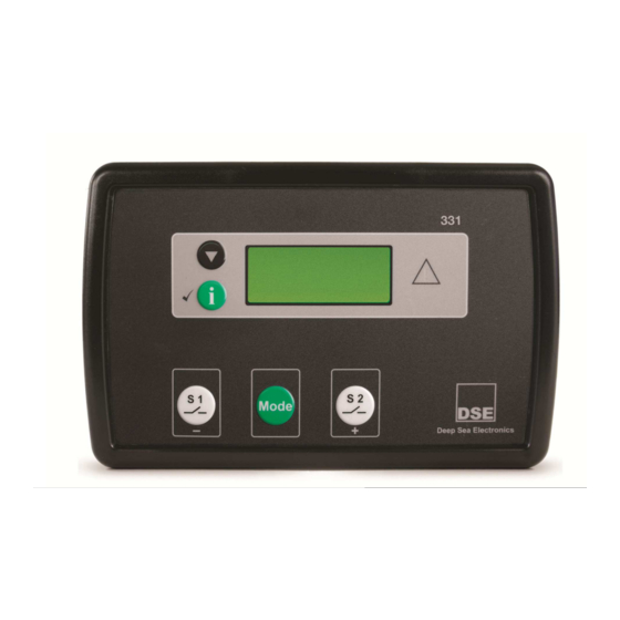
Description of Controls 5 DESCRIPTION OF CONTROLS The following section details the function and meaning of the various controls on the module. Main status display Display Scroll button Common Alarm Indicator Info button S1 breaker control Select Mode S2 breaker control... -
Page 17: Quickstart Guide
Description of Controls QUICKSTART GUIDE This section provides a quick start guide to the module’s operation. 5.1.1 MODE SELECTION OPERATION Press button to confirm selected Press button until preferred mode is selected. NOTE:- For further details, see the section entitled ‘MODE SELECTION’ elsewhere in this manual. -
Page 18: Graphical Display
Description of Controls 5.2 GRAPHICAL DISPLAY 4- line, 64 x 132 small Graphic Display with LED Backlight Icon and numeric display. Switch to select ‘Icon’ or ‘English’ display Software controlled contrast Mimic of Text insert / 4x indicators via LCD 5.2.1 DISPLAY PAGES It is possible to scroll to display the different pages of information by repeatedly operating the scroll button Once selected the page will remain on the LCD display until the user selects a different page or after an extended... -
Page 19: Alarms
Description of Controls 5.2.1.3 ALARMS Lists any current alarms Example (English) (Icon) 5.2.1.4 SCHEDULER. Shows the settings of the exercise scheduler Example: 5.2.2 ALARM ICONS In instances where more than one alarm is present the icon area will transition between icons to display all active alarm conditions. -
Page 20: Controls
Description of Controls 5.3 CONTROLS 5.3.1 MODE SELECTION NOTE:- Icons only apply when display mode in the software programme is set to `icons` This button selects the preferred mode of operation. to complete the selection press the button. Automatic mode. This mode allows the module to control the function of the load switching completely automatically. -
Page 21: Operation
Operation 6 OPERATION 6.1 AUTOMATIC MODE OF OPERATION NOTE:- If a digital input configured to external panel lock is active, changing module modes will not be possible. Viewing the instruments is NOT affected by panel lock. Activate auto mode by pressing the mode button until Auto is selected and then press the button to confirm. -
Page 22: Manual Operation
Operation 6.2 MANUAL OPERATION NOTE:- If a digital input configured to panel lock is active, changing module modes will not be possible. Viewing the instruments and event logs is NOT affected by panel lock. Manual mode allows the operator to change the state of the load switching devices. 6.2.1 STARTING SEQUENCE NOTE:- There is no start delay in this mode of operation. -
Page 23: Test On Operation
Operation 6.3 TEST ON OPERATION NOTE:- If a digital input configured to panel lock is active, changing module modes will not be possible. Viewing the instruments and event logs is NOT affected by panel lock. Test mode allows the operator to start and stop the set manually, and if required change the state of the load switching devices. -
Page 24: Load Switching Control
Operation 6.4 LOAD SWITCHING CONTROL The following timing diagrams detail the differences between the load switching control options. 6.4.1 BREAKER SCHEME A NOTE : S2 Closed Auxiliary and S1 Closed Auxiliary inputs do not affect the operation of the load switching in Breaker Scheme A 6.4.2 S1 / S2 LOAD INHIBIT... -
Page 25: Breaker Scheme B
Operation 6.4.5 BREAKER SCHEME B Breaker Scheme B is intended only for use with certain designs of transfer switch. If you are using contactors, you MUST select Breaker Scheme A. 6.4.5.1 CHECK SYNCHRONISING IS DISABLED 6.4.5.1.1 TRANSFERRING TO S2 To open S2 breaker the Open S1 output energises, it then de-energises when the S1 Closed Auxiliary indicates it has successfully opened, or after 1s whichever occurs first. -
Page 26: Check Synchronising Is Enabled
Operation 6.4.5.2 CHECK SYNCHRONISING IS ENABLED NOTE : The module waits indefinitely for synchronisation unless the ‘Return to programmed transition’ function is active in which case after 2 minutes it performs a non-sync transfer as described in the previous section. NOTE : The transfer time is ignored during a check-sync but is used if the transfer fails and it performs a non-sync transfer. -
Page 27: Protections
Protections 7 PROTECTIONS 7.1 S2 The 331 ATS module monitors the S2 supply to ensure that it remains within configured levels. If the S2 supply fails, it is taken off load and the start/run signal is be removed. S2 failure S2 has not become available after the period of the S2 Failure timer has expired. -
Page 28: Front Panel Configuration
Front Panel Configuration 8 FRONT PANEL CONFIGURATION This configuration mode allows the operator limited customising of the way the module operates. Use the module’s navigation buttons to traverse the menu and make value changes to the parameters: Next page Edit /Accept Increase value / next item value. -
Page 29: Accessing The Front Panel Editor (Fpe)
Front Panel Configuration 8.1 ACCESSING THE FRONT PANEL EDITOR (FPE) To enter the ‘configuration mode’ press Press and hold the button NOTE:- To exit the front panel configuration editor and activate your changes, press and hold the button. Ensure you have saved any changes you have made by pressing the button first. - Page 30 Front Panel Configuration CONFIGURATION PARAMETERS – INPUTS (Page 3) Digital Input A Source 0 (Input Source List) Digital Input A Polarity 0 (Input Polarity List) Digital Input B Source 0 (Input Source List) Digital Input B Polarity 0 (Input Polarity List) Digital Input C Source 0 (Input Source List) Digital Input C Polarity...
- Page 31 Front Panel Configuration CONFIGURATION PARAMETERS – S2 (Page 7) Immediate S2 dropout On (1), Off (0) Under voltage enable (Generator Option) On (1), Off (0) Under voltage trip (Generator Option) Loading voltage (Generator Option) Over voltage enable (Generator Option) On (1), Off (0) Over voltage trip (Generator Option) Under frequency enable (Generator Option) On (1), Off (0)
- Page 32 Front Panel Configuration Parameters with multiple choices use the following identification tables for the parameter values: INPUT SOURCE LIST Not used Alarm Reset Alarm Mute Auto Restore Inhibit Auto Start Inhibit Auxiliary S2 Available Auxiliary S1 Fail S2 Load Inhibit S2 Closed Auxiliary Inhibit Scheduled Run Lamp Test...
- Page 33 Front Panel Configuration OUTPUT SOURCE LIST Not Used Audible Alarm Battery High Voltage Battery Low Voltage Close S2 Output Close S2 Output Pulse Close S1 Output Close S1 Output Pulse Close to N Output Close to N Output Pulse Common Warning Cooling Down Digital Input A Digital Input B...
-
Page 34: Maintenance, Spares, Repair And Servicing
Maintenance, Spares, Repairs, Servicing, Warranty, Disposal 9 MAINTENANCE, SPARES, REPAIR AND SERVICING The DSE331 Series controller is designed to be Fit and Forget. As such, there are no user serviceable parts within the controller. In the case of malfunction, you should contact your original equipment supplier (OEM). -
Page 35: Warranty
Maintenance, Spares, Repairs, Servicing, Warranty, Disposal 10 WARRANTY DSE provides limited warranty to the equipment purchaser at the point of sale. For full details of any applicable warranty, you are referred to your original equipment supplier (OEM). 11 DISPOSAL 11.1 WEEE (WASTE ELECTRICAL AND ELECTRONIC EQUIPMENT) -
Page 36: Appendix
12.1 COMMUNICATIONS OPTION CONNECTIONS 12.1.1 DESCRIPTION The DSE Configuration Suite software allows the controller to communicate with a PC. The computer connects to the module as shown below and allows easy adjustment of the operating parameters and firmware update of the controller. - Page 37 This Page is Intentionally blank...
- Page 38 This Page is Intentionally blank...
Need help?
Do you have a question about the DSE331 and is the answer not in the manual?
Questions and answers