
Related Manuals for DSE DSE701 MKII


Summary of Contents for DSE DSE701 MKII
- Page 1 DEEP SEA ELECTRONICS PLC DSE701 MKII CONTROLLER OPERATORS MANUAL Document number 057-144 Author: Ashley Senior...
- Page 2 Applications for the copyright holder’s written permission to reproduce any part of this publication should be addressed to Deep Sea Electronics Plc at the address above. The DSE logo is a UK registered trademark of Deep Sea Electronics PLC. Any reference to trademarked product names used within this publication is owned by their respective companies.
-
Page 3: Table Of Contents
NEGATIVE EARTH ..........................16 4.3.1.2 POSITIVE EARTH ..........................16 4.3.1.3 FLOATING EARTH ..........................16 DESCRIPTION OF CONTROLS ..................17 4.4.1 DSE701 MKII KEYSWTICH CONTROLLER .............. 17 4.4.2 QUICKSTART GUIDE ....................18 4.4.3 CONTROLS ........................ 18 OPERATION....................19 AUTOMATIC MODE OF OPERATION................19 5.1.1... - Page 4 DSE701 MkII Operators Manual COMMISSIONING ..................22 PRE-COMMISSIONING ..................... 22 FAULT FINDING .................... 23 MAINTENANCE, SPARES, REPAIR AND SERVICING ........ 24 WARRANTY ....................24 DISPOSAL ....................24 11.1 WEEE (WASTE ELECTRICAL AND ELECTRONIC EQUIPMENT) ......24 11.2 ROHS (RESTRICTION OF HAZARDOUS SUBSTANCES) .......... 24...
-
Page 5: Bibliography
This is not a controlled document. You will not be automatically informed of updates. Any future updates of this document will be included on the DSE website at www.deepseaplc.com The DSE701 MkII controller is used to start and stop a engine and indicate fault conditions. The DSE701 MkII will automatically shut the engine down upon fault. -
Page 6: Specifications
Initial controller release The standard DSE701 MkII is configured to sense the speed of the engine through an AC Frequency Hz or RPM. Using the DSE813 interface and DSE Configuration Suite Lite Software the module can be configured to sense speed through an MPU sensor. -
Page 7: Inputs
Magnetic Pickup devices can often be ‘shared’ between two or more devices. For example, one device can often supply the signal to both the DSE701 MkII speed switch and the engine governor. The possibility of this depends upon the amount of current that the magnetic pickup can supply. -
Page 8: Charge Fail Input/Output
In a failed charge situation, the voltage of this terminal is pulled down to a low voltage. It is this drop in voltage that triggers the charge failure alarm. The level at which this operates and whether this triggers a warning or shutdown alarm is configurable using the DSE Config Suite Lite Software. 3.6 OUTPUTS 3.6.1... -
Page 9: Pc Configuration
Max distance 6m (yards) 3.7.1 PC COMMUNICATION Using the DSE813 interface, the DSE701 MkII controller can connect to a computer to enable simple configuration of parameters. Connection details for the DSE813 USB Interface are documented in DSE publication: 057-145 DSE701 MkII Configuration Suite Lite Software Manual To connect a DSE701 MkII controller to a PC, the following items are required: •... -
Page 10: Dimensions And Mounting
Specification 3.8 DIMENSIONS AND MOUNTING 3.8.1 DIMENSIONS 72 mm x 72 mm x 38 mm (2.8” x 2.8” x 1.5”) 3.8.2 PANEL CUTOUT 68 mm x 68 mm (2.7” x 2.7”) 3.8.3 WEIGHT 0.08 kg (0.176 lb) 3.8.4 FIXING CLIPS The module is held into the panel fascia using the supplied fixing clips. -
Page 11: Applicable Standards
Specification 3.9 APPLICABLE STANDARDS BS 4884-1 This document conforms to BS4884-1 1992 Specification for presentation of essential information. BS 4884-2 This document conforms to BS4884-2 1993 Guide to content BS 4884-3 This document conforms to BS4884-3 1993 Guide to presentation BS EN 60068-2-1 -30°C (-22°F) (Minimum temperature) -
Page 12: Enclosure Classifications
Specification 3.9.1 ENCLOSURE CLASSIFICATIONS IP CLASSIFICATIONS DSE701 MkII BS EN 60529 Degrees of protection provided by enclosures IP41 (front of controller when controller is installed into the control panel WITHOUT being sealed to the panel) IP54 Rear of controller(suitable grease should be applied to terminals if exposed to a harsh environment... -
Page 13: Nema Classifications
Specification NEMA CLASSIFICATIONS DSE701 MkII NEMA Rating (Approximate) 2 (front of controller when controller is installed into the control panel WITHOUT being sealed to the panel) Rear of controller (suitable grease should be applied to terminals if exposed to a harsh environment) NOTE: - There is no direct equivalence between IP / NEMA ratings. -
Page 14: Installation
Installation 4 INSTALLATION The DSE701 MkII controller is designed to be mounted on the panel fascia. For dimension and mounting details, see the section entitled Specification, Dimension and mounting elsewhere in this document. 4.1 USER CONNECTIONS Terminals 10-11 Terminals 1-9... -
Page 15: Typical Wiring Diagrams
4.3 TYPICAL WIRING DIAGRAMS As every system has different requirements, these diagrams show only a TYPICAL system and do not intend to show a complete system. Further wiring suggestions are available in the following DSE publications, available at www.deepseaplc.com to website members. -
Page 16: Earth Systems
The typical wiring diagrams located within this document show connections for a negative earth system (the battery negative connects to Earth) 4.3.1.2 POSITIVE EARTH When using a DSE controller with a Positive Earth System (the battery positive connects to Earth), the following points must be followed: •... -
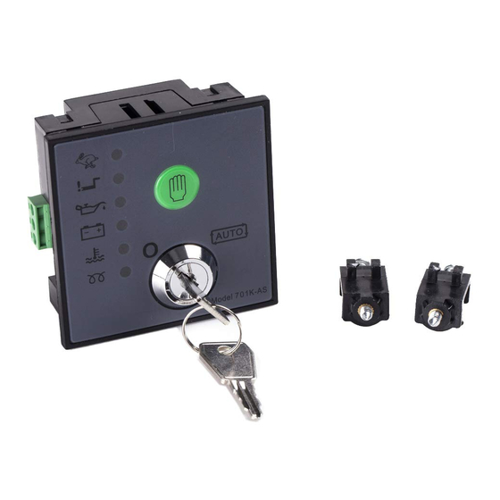
Page 17: Description Of Controls
Description of Controls 4.4 DESCRIPTION OF CONTROLS The following section details the function and meaning of the various controls on the controller. 4.4.1 DSE701 MKII KEYSWTICH CONTROLLER Engine start button (only when input not configured to remote start) Key switch “I” on position... -
Page 18: Quickstart Guide
Installation 4.4.2 QUICKSTART GUIDE This section provides a quick start guide to the controller’s operation Insert Key and turn to position I Turn and hold to position II, crank and start. 4.4.3 CONTROLS Stop /Reset This key switch position places the module into its Stop/Reset mode. This will clear any alarm conditions for which the triggering criteria have been removed. -
Page 19: Operation
ALARM CONDITION When the engine fires, the starter motor is disengaged. Speed detection is factory configured to the customers specification upon ordering but can changed using the DSE Configuration Suite Lite PC Software in conjunction with the DSE813 USB Interface. -
Page 20: Manual Operation
ALARM CONDITION When the engine fires, the starter motor is disengaged. Speed detection is factory configured to the customers specification upon ordering but can changed using the DSE Configuration Suite Lite PC Software in conjunction with the DSE813 USB Interface. -
Page 21: Protections
Protections 6 PROTECTIONS 6.1 SHUTDOWN A flashing LED indicates a shutdown alarm. Shutdowns are critical alarm conditions that stop the engine and draw the operator’s attention to an undesirable condition. Shutdown alarms are latching. The fault must be removed and the key switch turned to the position to reset the module. -
Page 22: Commissioning
• Check all other parts in the system according to the manufacturer documentation. • Thoroughly review the configuration of the DSE controller and check that all parameters meet the requirements of your system. • +To check the start cycle operation, take appropriate measures to prevent the engine from starting (disable the operation of the fuel solenoid). -
Page 23: Fault Finding
Fault Finding 8 FAULT FINDING SYMPTOM POSSIBLE REMEDY Unit is inoperative Check the battery and wiring to the unit. Check the DC supply. Check the DC Read/Write configuration does not fuse. operate Unit shuts down Check DC supply voltage is not above 35 Volts or below 9 Volts Check the operating temperature is not above 70°... -
Page 24: Maintenance, Spares, Repair And Servicing
Maintenance 9 MAINTENANCE, SPARES, REPAIR AND SERVICING The DSE701 MKII controller is Fit and Forget. As such, there are no user serviceable parts within the controller. In the case of malfunction, you should contact your original equipment manufacturer (OEM). 10 WARRANTY DSE provides limited warranty to the equipment purchaser at the point of sale. - Page 25 This page is intentionally left blank...
- Page 26 This page is intentionally left blank...
Need help?
Do you have a question about the DSE701 MKII and is the answer not in the manual?
Questions and answers