
Related Manuals for DSE DSE4510


Summary of Contents for DSE DSE4510
- Page 1 DEEP SEA ELECTRONICS PLC DSE4510 & DSE4520 Operator Manual Document Number: 057-171 Author: Fady Atallah DSE4510 & DSE4520 Operator Manual ISSUE 4 https://bestgenerator.spb.ru/?page_id=7195 http://bestgenerator.spb.ru/?page_id=6765...
- Page 2 Applications for the copyright holder’s written permission to reproduce any part of this publication should be addressed to Deep Sea Electronics Plc at the address above. The DSE logo is a UK registered trademarks of Deep Sea Electronics PLC. Any reference to trademarked product names used within this publication is owned by their respective companies.
-
Page 3: Table Of Contents
DSE4510 & DSE4520 Operator Manual TABLE OF CONTENTS Section Page BIBLIOGRAPHY ....................6 INSTALLATION INSTRUCTIONS .................. 6 TRAINING GUIDES ......................6 MANUALS ........................6 THIRD PARTY DOCUMENTS ..................6 INTRODUCTION ....................7 SPECIFICATIONS .................... 8 SHORT NAMES ......................8 OPERATING TEMPERATURE ..................8 REQUIREMENTS FOR UL CERTIFICATION .............. - Page 4 4.1.6 PC CONFIGURATION INTERFACE CONNECTOR ..........30 TYPICAL WIRING DIAGRAM ..................31 4.2.1 DSE4510 TYPICAL WIRING DIAGRAM (3 PHASE 4 WIRE) ......... 32 4.2.2 DSE4520 TYPICAL WIRING DIAGRAM (3 PHASE 4 WIRE) ......... 33 ALTERNATE TOPOLOGY WIRING DIAGRAMS ............34 4.3.1...
- Page 5 ALARMS ........................85 COMMUNICATIONS ..................... 85 INSTRUMENTS ......................85 MISCELLANEOUS ....................... 86 MAINTENANCE, SPARES, REPAIR AND SERVICING ......87 10.1 PURCHASING ADDITIONAL CONNECTOR PLUGS FROM DSE ......87 10.1.1 PACK OF PLUGS ....................87 10.1.2 INDIVIDUAL PLUGS ....................87 10.2 PURCHASING ADDITIONAL FIXING CLIPS FROM DSE .........
-
Page 6: Bibliography
Bibliography 1 BIBLIOGRAPHY This document refers to and is referred to by the following DSE publications which can be obtained from the DSE website: www.deepseaplc.com 1.1 INSTALLATION INSTRUCTIONS Installation instructions are supplied with the product in the box and are intended as a ‘quick start’... -
Page 7: Introduction
Introduction 2 INTRODUCTION This document details the installation and operation requirements of the DSE4510 & DSE4520 modules, part of the DSEGenset® range of products. The manual forms part of the product and should be kept for the entire life of the product. If the product is passed or supplied to another party, ensure that this document is passed to them for reference purposes. -
Page 8: Specifications
Short Name Description DSE4000,DSE4xxx All modules in the DSE4000 range. DSE4500,DSE45xx All modules in the DSE4500 range. DSE4510 DSE4510 module/controller DSE4520 DSE4520 module/controller 3.2 OPERATING TEMPERATURE Module Description DSE45xx -30ºC to +70ºC (-40ºC to +70ºC for variants fitted with display heaters) 3.3 REQUIREMENTS FOR UL CERTIFICATION... -
Page 9: Terminal Specification
Specification 3.4 TERMINAL SPECIFICATION NOTE: For purchasing additional connector plugs from DSE, please see the section entitled Maintenance, Spares, Repair and Servicing elsewhere in this document. Two part connector. Male part fitted to • module Female part supplied in •... -
Page 10: Voltage & Frequency Sensing
Specification 3.6 VOLTAGE & FREQUENCY SENSING Measurement Type True RMS conversion Sample Rate 5kHz or better Harmonics Up to 11 or better Input Impedance 300kΩ phase to neutral to 415V AC (absolute maximum) (minimum required for sensing frequency Phase To Neutral Suitable for 345V nominal (±20% for under/overvoltage detection) to 720V AC... -
Page 11: Va Rating Of The Cts
CT is approximately 7VA. CT’s required in this instance is at least 7.5VA (7+0.5). NOTE: Details for 4mm² cables are shown for reference only. The connectors on the DSE modules are only suitable for cables up to 2.5mm². -
Page 12: Ct Polarity
3.7.3 CT PHASING Take particular care that the CTs are connected to the correct phases. For instance, ensure that the CT on phase 1 is connected to the terminal on the DSE module intended for connection to the CT for phase 1. -
Page 13: Inputs
Specification 3.8 INPUTS 3.8.1 DIGITAL INPUTS 4 configurable digital inputs Number (7 when Analogue Inputs are configured as digital inputs) Arrangement Contact between terminal and ground Low Level Threshold 3.2V minimum High Level Threshold 8.1V maximum Maximum Input Voltage +60V DC with respect to plant supply negative Minimum Input Voltage -24V DC with respect to plant supply negative Contact Wetting Current... -
Page 14: Fuel Level Sensor
It is this drop in voltage that triggers the charge failure alarm. The level at which this operates and whether this triggers a warning or shutdown alarm is configurable using the DSE Configuration Suite Software. -
Page 15: Outputs
(CAN) transports data gathered by the engine controller interface. This allows generator controllers to access these engine parameters with no physical connection to the sensor device. NOTE: For further details on connection to electronic engines, refer to DSE Publication: 057-004 Electronic Engines And DSE Wiring... -
Page 16: Usb Connection
The USB port is provided to give a simple means of connection between a PC and the controller. Using the DSE Configuration Suite Software, the operator is then able to control the module, starting or stopping the generator, selecting operating modes, etc. -
Page 17: Adding An External Sounder
Specification 3.11 ADDING AN EXTERNAL SOUNDER Should an external alarm or indicator be required, this can be achieved by using the DSE Configuration Suite PC software to configure an auxiliary output for “Audible Alarm”, and by configuring an auxiliary input for “Alarm Mute” (if required). -
Page 18: Dimensions And Mounting
Specification 3.13 DIMENSIONS AND MOUNTING 3.13.1 DIMENSIONS 140.0mm x 113mm x 43mm (5.5” x 4.4” x 1.7”) 3.13.2 PANEL CUTOUT 118mm x 92mm (4.6” x 3.6”) 3.13.3 WEIGHT 0.16kg (0.35lb) -
Page 19: Fixing Clips
Specification 3.13.4 FIXING CLIPS The module is held into the panel fascia using the supplied fixing clips. Withdraw the fixing clip screw (turn anticlockwise) until only the pointed end is protruding • from the clip. • Insert the three ‘prongs’ of the fixing clip into the slots in the side of the module case. Pull the fixing clip backwards (towards the back of the module) ensuring all three prongs of •... -
Page 20: Silicon Sealing Gasket
Specification 3.13.5 SILICON SEALING GASKET NOTE: For purchasing an additional silicon gasket from DSE, please see the section entitled Maintenance, Spares, Repair and Servicing elsewhere in this document. The optional silicon gasket provides improved sealing between module and the panel fascia. -
Page 21: Applicable Standards
Specification 3.13.6 APPLICABLE STANDARDS This document conforms to BS4884-1 1992 Specification for BS 4884-1 presentation of essential information. BS 4884-2 This document conforms to BS4884-2 1993 Guide to content BS 4884-3 This document conforms to BS4884-3 1993 Guide to presentation BS EN 60068-2-1 -30°C (-22°F) (Minimum temperature) - Page 22 Specification IEEE C37.2 Continued (Standard Electrical 50 – Instantaneous Overcurrent Relay Power System Device 52 – AC Circuit Breaker Function Numbers and Contact Designations) 53 – Exciter Or DC Generator Relay 54 – Turning Gear Engaging Device 59AC – AC Overvoltage Relay 59DC –...
-
Page 23: Enclosure Classifications
Specification 3.13.7 ENCLOSURE CLASSIFICATIONS 3.13.7.1 IP CLASSIFICATIONS The modules specification under BS EN 60529 Degrees of protection provided by enclosures IP65 (Front of module when module is installed into the control panel with the optional sealing gasket). IP42 (front of module when module is installed into the control panel WITHOUT being sealed to the panel) First Digit Second Digit Protection against contact and ingress of solid objects... -
Page 24: Nema Classifications
Specification 3.13.7.2 NEMA CLASSIFICATIONS THE MODULES NEMA RATING (APPROXIMATE) 12 (Front of module when module is installed into the control panel with the optional sealing gasket). 2 (front of module when module is installed into the control panel WITHOUT being sealed to the panel) NOTE: There is no direct equivalence between IP / NEMA ratings. -
Page 25: Installation
Installation – Terminal Description 4 INSTALLATION The module is designed to be mounted on the panel fascia. For dimension and mounting details, see the section entitled Specification, Dimension and mounting elsewhere in this document. 4.1 TERMINAL DESCRIPTION To aid user connection, icons are used on the rear of the module to help identify terminal functions. An example of this is shown below. -
Page 26: Dc Supply, Fuel And Start Outputs, Outputs C, D, E & F
Plant Supply Positive from terminal 2. 2 Amp rated. AWG 18 NOTE: Terminals 8 & 9 are not fitted to DSE4510 controller. NOTE: When the module is configured for operation with an electronic engine, FUEL and START output requirements may be different. For further details on connection to electronic... -
Page 27: Analogue Sensor
NOTE: If you use PTFE insulating tape on the sensor thread when using earth return sensors, ensure you do not insulate the entire thread, as this will prevent the sensor body from being earthed via the engine block. NOTE: For further details of module configuration, refer to DSE Publication: 057-172 DSE45xx Configuration Software Manual. -
Page 28: Configurable Digital Inputs & Can
NOTE: Screened 120Ω Ω Ω Ω impedance cable specified for use with CAN must be used for the CAN link. DSE stock and supply Belden cable 9841 which is a high quality 120Ω Ω Ω Ω impedance cable suitable for CAN use (DSE part number 016-030) 4.1.4... -
Page 29: Geneator Current Transformers
L is the primary of the CT that ‘points’ towards the Load s1 is the secondary of the CT that connects to the DSE Module’s input for the CT measuring s2 is the secondary of the CT that should be commoned with the s2 connections of all the other CTs and connected to the CT common terminal of the module. -
Page 30: Pc Configuration Interface Connector
CAUTION!: Care must be taken not to overload the PCs USB system by connecting more than the recommended number of USB devices to the PC. For further information, consult your PC supplier. NOTE: For further details of module configuration, refer to DSE Publication: 057-172 DSE45xx Configuration Software Manual. -
Page 31: Typical Wiring Diagram
Genset manufacturers and panel builders may use these diagrams as a starting point; however, you are referred to the completed system diagram provided by your system manufacturer for complete wiring detail. Further wiring suggestions are available in the following DSE publications, available at www.deepseaplc.com to website members. -
Page 32: Dse4510 Typical Wiring Diagram (3 Phase 4 Wire)
Installation – Typical Wiring Diagrams 4.2.1 DSE4510 TYPICAL WIRING DIAGRAM (3 PHASE 4 WIRE) NOTE: Terminals 29-32 are not fitted on the DSE45xx-01 variant. -
Page 33: Dse4520 Typical Wiring Diagram (3 Phase 4 Wire)
Installation – Typical Wiring Diagrams 4.2.2 DSE4520 TYPICAL WIRING DIAGRAM (3 PHASE 4 WIRE) NOTE: Terminals 29-32 are not fitted on the DSE45xx-01 variant. -
Page 34: Alternate Topology Wiring Diagrams
Installation – Alternate Topology Wiring Diagrams 4.3 ALTERNATE TOPOLOGY WIRING DIAGRAMS 4.3.1 GENERATOR... -
Page 35: Mains (4520 Only)
Installation – Alternate Topology Wiring Diagrams 4.3.2 MAINS (4520 ONLY) -
Page 36: Earth Systems
(the battery negative connects to Earth) 4.4.2 POSITIVE EARTH When using a DSE module with a Positive Earth System (the battery positive connects to Earth), the following points must be followed: Follow the typical wiring diagram as normal for all sections EXCEPT the earth points •... -
Page 37: Description Of Controls
Description Of Controls 5 DESCRIPTION OF CONTROLS NOTE: The following descriptions detail the sequences followed by a module containing the standard ‘factory configuration’. Always refer to your configuration source for the exact sequences and timers observed by any particular module in the field. Control of the module is via push buttons mounted on the front of the module with Stop/Reset Mode , Auto Mode... -
Page 38: Control Push-Buttons
Description Of Controls 5.1 CONTROL PUSH-BUTTONS Icon Description Stop / Reset Mode This button places the module into its Stop/Reset Mode . This will clear any alarm conditions for which the triggering criteria have been removed. If the engine is running and the module is put into Stop mode, the module will automatically instruct the generator to unload (‘Close Generator’... -
Page 39: Module Display
The module’s display contains the following sections. Description of each section can be viewed in the sub sections. NOTE: Depending upon the module’s configuration, some display screens may be disabled. For further details of module configuration, refer to DSE Publication: 057-172 DSE45xx Configuration Software Manual. Inst. -
Page 40: Instrumentation Icons
Viewing The Instrument Pages 5.2.1 INSTRUMENTATION ICONS When viewing instrumentation pages, an icon is displayed in the Inst. Icon section to indicate what section is currently being displayed. Icon Details The default home page which displays generator voltage and mains voltage (DSE4520 only) Generator voltage and frequency instrumentation screen Mains voltage and frequency instrumentation screen (DSE4520 only) Generator current instrumentation screen... -
Page 41: Active Configuration
Viewing The Instrument Pages 5.2.2 ACTIVE CONFIGURATION An icon is displayed in the Active Config section to indicate the active configuration within the currently selected within the controller. Icon Details Appears when the main configuration is selected. Appears when the alternative configuration is selected. 5.2.3 FRONT PANEL EDITOR (FPE) / AUTO RUN ICON NOTE: For further details about the Front Panel Editor, see the section entitled ‘Front Panel Editor’... -
Page 42: Load Switching Icon
Viewing The Instrument Pages 5.2.5 LOAD SWITCHING ICON An icon is displayed in the Load Switching Icon section to indicate the current operation status of the controller. Icon Details Appears when the generator is at rest or not available and when the generator breaker is open. -
Page 43: Alarm Icons (Protections)
Example: If the DSE controller was sensing a charge alternator failure alarm, delay over current alarm and a AC under voltage alarm at the same time, it would cycle through all of the icons to show this. -
Page 44: Warning Alarm Icons
By default, warning alarms are self-resetting when the fault condition is removed. However enabling ‘all warnings are latched’ will cause warning alarms to latch until reset manually. This is enabled using the DSE Configuration Suite in conjunction with a compatible PC. Icon... -
Page 45: Electrical Trip Alarm Icons
Viewing The Instrument Pages 5.2.7.2 ELECTRICAL TRIP ALARM ICONS Electrical trips are latching and stop the Generator but in a controlled manner. On initiation of the electrical trip condition the module de-energises all the ‘Delayed Load Output’ and the ‘Close Gen Output’... -
Page 46: Shutdown Alarm Icons
Viewing The Instrument Pages 5.2.7.3 SHUTDOWN ALARM ICONS Shutdown alarms are latching and immediately stop the Generator. On initiation of the shutdown condition the module de-energises all the ‘Delayed Load Output’ and the ‘Close Gen Output’ outputs to remove the load from the generator. Once this has occurred, the module shuts the generator set down immediately to prevent further damage. - Page 47 Viewing The Instrument Pages Icon Fault Description Generator Under The generator output frequency has fallen below the pre-set alarm Frequency setting after the Safety On timer has expired. Generator Over The generator output frequency has risen above the pre-set alarm Frequency setting.
-
Page 48: Viewing The Instrument
Viewing The Instrument Pages 5.3 VIEWING THE INSTRUMENT PAGES 5.3.1 NAVIGATION MENU To enter the navigation menu, press both the (up) and (down) buttons simultaneously. To select the required icon, press the (up) button to cycle right or the (down) button to cycle left until the desired instrumentation section is reached. -
Page 49: General Navigation
(Page Delay Timer), the module reverts back to the Home ) page. The Page Delay Timer is configurable using the DSE Configuration Suite Software or by using the Front Panel Editor. NOTE: For further details of module configuration, refer to DSE Publication: 057-172... -
Page 50: Home
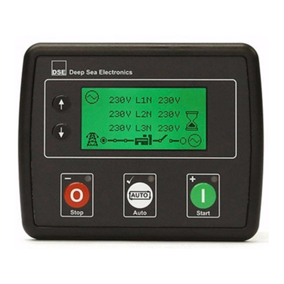
Viewing The Instrument Pages 5.3.3 HOME This is the page that is displayed when no other page has been selected and is automatically displayed after a period of inactivity (Page Delay Timer) of the module facia buttons. It also contains the voltage reading of the generator and mains that is measured from the module’s voltage inputs. -
Page 51: Mains (Dse4520 Only)
Viewing The Instrument Pages 5.3.5 MAINS (DSE4520 ONLY) These pages contain electrical values of the mains, measured or derived from the module’s voltage inputs. Mains Voltage (ph-N) • Mains Voltage (ph-ph) • Mains Frequency • 5.3.6 LOAD These pages contain electrical values of the load, measured or derived from the module’s voltage and current inputs. -
Page 52: Engine
Viewing The Instrument Pages 5.3.7 ENGINE These pages contain instrumentation gathered about the engine measured or derived from the module’s inputs, some of which may be obtained from the engine ECU. 1500 Engine Speed • Engine Run Time • Engine Battery Volts •... -
Page 53: Engine Dtc (Ecu Alarms)
Viewing The Instrument Pages 5.3.9 ENGINE DTC (ECU ALARMS) If the DSE module is connected to an ECU, This page contains active Diagnostic Trouble Codes (DTC) only if the engine ECU generating a fault code. These are alarm conditions are detected by the engine ECU and displayed by the DSE controller. - Page 54 NOTE: For details on these code meanings, refer to the ECU instructions provided by the engine manufacturer, or contact the engine manufacturer for further assistance. NOTE: For further details on connection to electronic engines, refer to DSE Publication: 057-004 Electronic Engines And DSE Wiring...
-
Page 55: Event Log
Viewing The Instrument Pages 5.3.10 EVENT LOG This module’s event log contains a list of the last 15 record electrical trip or shutdown events and the engine hours at which they occurred. Once the log is full, any subsequent electrical trip or shutdown alarms overwrites the oldest entry in the log. -
Page 56: Operation
Operation 6 OPERATION NOTE: The following descriptions detail the sequences followed by a module containing the standard ‘factory configuration’. Always refer to your configuration source for the exact sequences and timers observed by any particular module in the field. 6.1 QUICKSTART GUIDE This section provides a quick start guide to the module’s operation. -
Page 57: Stopping The Engine
Operation 6.1.2 STOPPING THE ENGINE Select Stop/Reset mode. The generator is stopped. NOTE: For further details, see the section entitled ‘OPERATION’ elsewhere in this manual. -
Page 58: Stop/Reset Mode
Oil pressure sensor must indicate low oil pressure • When the engine has stopped, it is possible to send configuration files to the module from DSE Configuration Suite PC software and to enter the Front Panel Editor to change parameters. -
Page 59: Automatic Mode
NOTE: If the unit has been configured for CAN, compatible ECU’s receive the start command via CAN and transmit the engine speed to the DSE controller. If the engine fails to fire during this cranking attempt then the starter motor is disengaged for the crank rest duration after which the next start attempt is made. -
Page 60: Stopping Sequence
Operation 6.3.4 STOPPING SEQUENCE The return delay timer operates to ensure that the starting request has been permanently removed and isn’t just a short term removal. Should another start request be made during the cooling down period, the set returns on load. If there are no starting requests at the end of the return delay timer, the load is removed from the generator to the mains supply and the cooling timer is initiated. -
Page 61: Manual/Start Mode
Protected Start Mode setting in the DSE Configuration Suite Software NOTE: For further details of module configuration, refer to DSE Publication: 057-172 DSE45xx Configuration Software Manual. 6.4.2 STARTING SEQUENCE NOTE: There is no start delay in this mode of operation. -
Page 62: Engine Running
Operation 6.4.3 ENGINE RUNNING Once the engine is running and all starting timers have expired, the animated Engine Running icon is displayed In manual mode, the load is not transferred to the generator unless a ‘loading request’ is made. A loading request can come from a number of sources. Activation of an auxiliary input that has been configured to Remote Start On Load or Auxiliary •... -
Page 63: Maintenance Alarm
Alarm x, where x is the type of maintenance alarm (Air, Fuel or Oil). • Pressing the maintenance reset button in the DSE Configuration Suite, Maintenance section. • Pressing and holding the Stop/Reset Mode button for 10 seconds on the desired Maintenance Alarm status page. -
Page 64: Scheduler
Up to 8 scheduled start/stop sequences can be configured to repeat on a 7-day or 28-day cycle. Scheduled runs may be on load or off load depending upon module configuration. Example Screen capture from DSE Configuration Suite Software showing the configuration of the Exercise Scheduler. -
Page 65: Front Panel Configuration
This configuration mode allows the operator to fully configure the module through its display without the use of the DSE Configuration Suite PC Software. Use the module’s facia buttons to traverse the menu and make value changes to the parameters: Next Section (101→201→... -
Page 66: Accessing The Front Panel Configuration Editor
PIN code set, this has been affected by your generator supplier who should be contacted if you require the code. If the code has been ‘lost’ or ‘forgotten’, the module must be returned to the DSE factory to have the module’s code removed. A charge will be made for this procedure. -
Page 67: Adjustable Parameters
Functionality in all DSE4510 & DSE4520 variants Functionality in all DSE4520 variants Functionality in DSE4510 & DSE4520 current sensing variants only Functionality in DSE4510 & DSE4520 RT & RTH variants only Configuration Parameters – Module (Page 1) Contrast 0 (%) -
Page 68: Input Settings
Front Panel Configuration 7.2.3 INPUT SETTINGS Configuration Parameters – Inputs (Page 3) Digital Input A Source 0 (Input Source) Digital Input A Polarity 0 (Polarity) Digital Input A Action (If Source = User Config) 0 (Action) Digital Input A Arming (If Source = User Config) 0 (Arming) Digital Input A Activation Delay (If Source = User Config) Digital Input B Source... -
Page 69: Output Settings
Functionality in all DSE4510 & DSE4520 variants Functionality in all DSE4520 variants Functionality in DSE4510 & DSE4520 current sensing variants only Functionality in DSE4510 & DSE4520 RT & RTH variants only Configuration Parameters – Outputs (Page 4) Digital Output A Source... -
Page 70: Generator Settings
Functionality in all DSE4510 & DSE4520 variants Functionality in all DSE4520 variants Functionality in DSE4510 & DSE4520 current sensing variants only Functionality in DSE4510 & DSE4520 RT & RTH variants only Configuration Parameters – Generator (Page 6) Alternator Fitted On (1), Off (0) -
Page 71: Mains Settings
Functionality in all DSE4510 & DSE4520 variants Functionality in all DSE4520 variants Functionality in DSE4510 & DSE4520 current sensing variants only Functionality in DSE4510 & DSE4520 RT & RTH variants only Configuration Parameters – Mains (Page 7) AC System 0 (AC System) -
Page 72: Engine Settings
Front Panel Configuration 7.2.8 ENGINE SETTINGS Configuration Parameters – Engine (Page 8) Start Attempts Over Speed Overshoot Over Speed Delay Gas Choke Timer (Gas Engine Only) Gas On Delay (Gas Engine Only) Gas Ignition Off Delay (Gas Engine Only) Crank Disconnect On Oil Pressure Enable On (1), Off (0) Check Oil Pressure Prior To Starting On (1), Off (0) -
Page 73: Analogue Inputs Settings
Front Panel Configuration 7.2.9 ANALOGUE INPUTS SETTINGS Configuration Parameters – Analogue Input Settings (Page 9) Analogue Input A Senor Type 0 (Sensor Type) Analogue Input A Sensor Selection 0 (Pressure Sensor List) Low Oil Pressure Enable On (1), Off (0) Low Oil Pressure Trip 0 Bar Oil Pressure Sender Open Circuit... -
Page 74: Scheduler Settings
Functionality in all DSE4510 & DSE4520 variants Functionality in all DSE4520 variants Functionality in DSE4510 & DSE4520 current sensing variants only Functionality in DSE4510 & DSE4520 RT & RTH variants only Configuration Parameters – Scheduler (Page 10) 1001 Enable Scheduler... -
Page 75: Maintenance Alarm Settings
Front Panel Configuration 7.2.12 MAINTENANCE ALARM SETTINGS Configuration Parameters – Maintenance Alarms (Page 12) 1201 Oil Maintenance Alarm Enable On (1), Off (0) 1202 Oil Maintenance Alarm Action 0 (Action) 1203 Oil Maintenance Alarm Engine Hours 1204 Air Maintenance Alarm Enable On (1), Off (0) 1205 Air Maintenance Alarm Action... - Page 76 Functionality in all DSE4510 & DSE4520 variants Functionality in all DSE4520 variants Functionality in DSE4510 & DSE4520 current sensing variants only Functionality in DSE4510 & DSE4520 RT & RTH variants only Configuration Parameters – Alternate Configuration (Page 20) 2024 CT Primary...
-
Page 77: Selectable Parameter Settings
7.3.1 INPUT SOURCES Functionality in all DSE4510 & DSE4520 variants Functionality in all DSE4520 variants Functionality in DSE4510 & DSE4520 current sensing variants only Functionality in DSE4510 & DSE4520 RT & RTH variants only INPUT SOURCES User Configured Alarm Mute... -
Page 78: Output Sources
7.3.2 OUTPUT SOURCES Functionality in all DSE4510 & DSE4520 variants Functionality in all DSE4520 variants Functionality in DSE4510 & DSE4520 current sensing variants only Functionality in DSE4510 & DSE4520 RT & RTH variants only OUTPUT SOURCES Not Used Air Flap Relay... - Page 79 Functionality in all DSE4510 & DSE4520 variants Functionality in all DSE4520 variants Functionality in DSE4510 & DSE4520 current sensing variants only Functionality in DSE4510 & DSE4520 RT & RTH variants only OUTPUT SOURCES Oil Pressure Sender Open Circuit Open Gen Output...
-
Page 80: Alarm Action
Front Panel Configuration 7.3.3 ALARM ACTION ALARM ACTION Index Action Electrical Trip Shutdown Warning 7.3.4 FLEXIBLE SENSOR ALARM ACTION FLEXIBLE SENSOR ALARM ACTION Index Action None Shutdown Electrical Trip 7.3.5 POWER UP MODE POWER UP MODE Index Mode Stop Manual Auto 7.3.6 SENSOR TYPE SENSOR TYPE... -
Page 81: Digital Input Alarm Arming
Front Panel Configuration 7.3.8 DIGITAL INPUT ALARM ARMING DIGITAL INPUT ALARM ARMING Index Arming Always From Safety On From Starting Never 7.3.9 DIGITAL INPUT POLARITY DIGITAL INPUT POLARITY Index Polarity Close to Activate Open to Activate 7.3.10 DIGITAL OUTPUT POLARITY OUTPUT POLARITY Index Polarity... -
Page 82: Pressure Sensor List
Front Panel Configuration 7.3.12 PRESSURE SENSOR LIST PRESSURE SENSOR LIST Index Type Not used Dig Closed for Alarm Dig Open for Alarm VDO 5 Bar VDO 10 Bar Datcon 5 Bar Datcon 10 Bar Datcon 7 Bar Murphy 7 Bar CMB812 Veglia User Defined... -
Page 83: Commissioning
NOTE: If Emergency Stop feature is not required, link the input to the DC Negative or disable the input. For further details of module configuration, refer to DSE Publication: 057- 172 DSE45xx Configuration Software Manual. To check the start cycle operation, take appropriate measures to prevent the engine from starting •... -
Page 84: Fault Finding
Commissioning - Fault Finding 9 FAULT FINDING 9.1 STARTING Symptom Possible Remedy Unit is inoperative Check the battery and wiring to the unit. Check the DC supply. Check the DC fuse. Read/Write configuration does not operate Unit shuts down Check DC supply voltage is not above 35 Volts or below 9 Volts Check the operating temperature is not above 70°C. -
Page 85: Alarms
CAN ECU WARNING This indicates a fault condition detected by the engine ECU and CAN ECU SHUTDOWN transmitted to the DSE controller. CAN DATA FAIL Indicates failure of the CAN data link to the engine ECU. Check all wiring and termination resistors (if required). -
Page 86: Miscellaneous
Commissioning - Fault Finding 9.6 MISCELLANEOUS Symptom Possible Remedy Module appears to ‘revert’ to When editing a configuration using the PC software it is vital that the an earlier configuration configuration is first ‘read’ from the controller before editing it. This edited configuration must then be “written”... -
Page 87: Maintenance, Spares, Repair And Servicing
In the case of malfunction, you should contact your original equipment manufacturer (OEM). 10.1 PURCHASING ADDITIONAL CONNECTOR PLUGS FROM DSE If you require additional plugs from DSE, please contact our Sales department using the part numbers below. 10.1.1 PACK OF PLUGS... -
Page 88: Warranty
Warranty 11 WARRANTY DSE provides limited warranty to the equipment purchaser at the point of sale. For full details of any applicable warranty, you are referred to your original equipment supplier (OEM). DISPOSAL 12.1 WEEE (WASTE ELECTRICAL AND ELECTRONIC EQUIPMENT)
Need help?
Do you have a question about the DSE4510 and is the answer not in the manual?
Questions and answers