Table of Contents
Advertisement
Quick Links
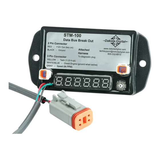
Data Bus Breakout for 2004 – 2010 Harley Davidson models
The STM-100 can be used to simplify the installation of an aftermarket speedometer and/or
tachometer on a 2004 – 2010 Harley Davidson motorcycle. The device converts the signals from the
data bus into traditional analog signals for a gauge of your choice. Outputs are provided for accessory
power and ground, tachometer signal (adjustable for 1, 2 or 4 cylinder outputs), speedometer signal
(8,000ppm) in addition to the Check Engine signal, normally only available on the data bus. The STM-
100 plugs directly into the diagnostics port and reads the signals from the ECM so there are no additional
sensors to wire.
In addition to the wired outputs, the STM-100 has an LED display that allows you to read and
clear diagnostic trouble codes, similar to a scan tool.
Included in the kit you should find:
STM-100
WIRING
Locate the four-pin diagnostic plug, typically found under the seat or side cover near the ECM.
The STM-100 will plug directly into the diagnostic plug. This will provide the power, ground, and data
into the STM-100.
*** Note: If you ever need to perform diagnostics or re-flash an ECM at a shop or dealer, unplug the STM-
100 to gain access to the diagnostic plug, after the work has been performed simply reconnect the STM-
100 to the diagnostic plug. All of your previous settings in the STM-100 are saved, so removing or
unplugging will not affect the setup.
STM-100
Heat Shrink
Manual
Power Harness
Signal Harness
MANUAL # 650324
Advertisement
Table of Contents

Related Manuals for Dakota Digital STM-100


Summary of Contents for Dakota Digital STM-100
- Page 1 100 plugs directly into the diagnostics port and reads the signals from the ECM so there are no additional sensors to wire. In addition to the wired outputs, the STM-100 has an LED display that allows you to read and clear diagnostic trouble codes, similar to a scan tool.
- Page 2 GRAY Speed signal out (8000 pulse per mile signal) The heat shrink supplied with the kit can be used to cover the wires between the STM-100 and gauge being installed for a “cleaner” looking installation. Wiring an external check engine light if your aftermarket gauge doesn’t have one can be done fairly easily.
- Page 3 DO NOT CONNECT SETUP The setup menus allow you to access the diagnostic capabilities of the STM-100 as well as allowing you to setup the tach output signal. Pay close attention to settings in these menus as incorrect settings could result in an incorrect reading at the gauge. Also know that you will still need to setup and/or calibrate the gauge that is being installed so you will have to refer to the gauge instructions for signal requirements and setup.
- Page 4 If you are replacing or removing the stock speedometer, you will want to select the “” option so the STM-100 will transmit some data back to the data bus to “trick” the bike into thinking it still has a stock speedometer present.
- Page 5 STM-100 should an update ever be needed. To access the menu, press and hold the setup switch on the STM-100 and turn the key on, release the switch. Press and release the switch until you get to the “” setup menu. When at the “” menu, press and hold the switch until “” is displayed, then release the switch.
- Page 6 SERVICE AND REPAIR DAKOTA DIGITAL offers complete service and repair of its product line. In addition, technical consultation is available to help you work through any questions or problems you may be having installing one of our products. Please read through the Troubleshooting Guide.
Need help?
Do you have a question about the STM-100 and is the answer not in the manual?
Questions and answers