Advertisement
Quick Links
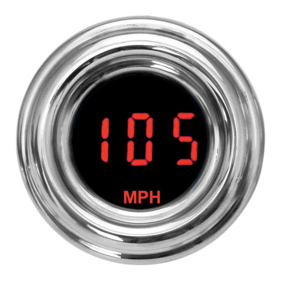
MCL-4000 SERIES 1-7/8" LED OIL PRESSURE GAUGE
User selectable ranges 0-30 PSI, 0-75 PSI, 0-150 PSI, 0-400 PSI (dependent on sender used)
User adjustable high and low pressure warning points
Fast or slow display update rates
Optional display dimming feature
MOUNTING
The MCL-4000 series gauge requires a round hole 1-7/8" diameter. It should be inserted into the opening from
the front and the U-clamp will be installed from the back. Tighten the two nuts on the U-clamp so that the gauge is secure.
Gauge depth to the back of the case is approximately 1-3/8". Gauge depth including the mounting studs is about 2-1/8".
PRESSURE GAUGE SETUP
The green wire in the harness is used to enter setup and change/select settings. This is done by powering the
green wire with +12V or releasing it. To power the green wire, touch the wire to a +12V source. To release the wire,
remove the green wire from the source. The gauge moves through the setup in the following order:
Software code > Sender selection > Low pressure warning > High pressure warning > update speed selection > done
default settings:
75 PSI sender
1. Make sure the key is off so the gauge is not powered.
2. Power the green wire while turning the key on.
3. The display will show "", this is the software code. (Newer software versions may have a different code.)
4. Release the green wire. The display will read "" (pressure sender selection).
5. Power and release the green wire. The currently selected pressure sender type is displayed.
6. Power and release the green wire until your pressure sender is displayed.
7. Power and hold the green wire to power to store the sender setting.
8. "" (low pressure warning) will be displayed. Release the green wire.
9. Power and release the green wire to adjust the low pressure warning point.
10. Power and hold power to the green wire to store the low pressure warning point.
11. "" (high pressure warning) will be displayed. Release green wire.
12. Power and release the green wire to adjust the high pressure warning point.
13. Power and hold power to the green wire to store the high pressure warning point.
14. "SPd" (update speed) will be displayed. Release green wire.
15. Power and release the green wire to adjust the update speed between "" (fast) and "" (slow).
16. Power and hold power to the green wire to save the update speed setting. Setup is complete. Gauge returns to
normal operation.
MCL-4032S/R
5.0 PSI low warning
52.0 PSI high warning
Slow update speed
MAN# 650187:A
Advertisement

Subscribe to Our Youtube Channel
Related Manuals for Dakota Digital MCL-4000 Series


Summary of Contents for Dakota Digital MCL-4000 Series
- Page 1 MOUNTING The MCL-4000 series gauge requires a round hole 1-7/8” diameter. It should be inserted into the opening from the front and the U-clamp will be installed from the back. Tighten the two nuts on the U-clamp so that the gauge is secure.
- Page 2 POWER RED WIRE Connect the red wire from the main harness to accessory power from the ignition switch. Never connect this to a battery charger alone. It needs to have a 12 volt battery connected to it. Battery chargers have an unregulated voltage output that will cause the system to not operate properly. GROUND BLACK WIRE AND RING TERMINAL The black wire is the main ground for the gauge.
- Page 3 24 months from date of original purchase. No person or representative is authorized to assume, for Dakota Digital, any liability other than expressed herein in connection with the sale of this product.
Need help?
Do you have a question about the MCL-4000 Series and is the answer not in the manual?
Questions and answers