Table of Contents
Advertisement
Quick Links
Included parts:
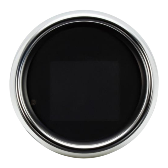
MLX-3000 display
IMPORTANT NOTE!
miles (160km) of operation. See "preset odometer" on page 7 for instructions.
Installation
The MLX-3000 is a direct-fit replacement and uses the original housing, gaskets and screws.
1. On tank-mount models, begin by removing the dash. All models: remove the two screws on the back of the gauge
housing, then unplug the factory gauge, noting the position of the rubber gaskets; one on the front between the
gauge bezel and housing and (on handlebar-mount applications) one on the back between the housing and the
back plate.
2. Transfer the original gaskets to the MLX-3000; connect the supplied power, indicator and speed harnesses. Also
connect the optional MBM harness if readings for compass, boost or air pressure are desired. Route the MBM
harness under the seat.
3. Secure the new gauge using the original screws.
3 3/8" Speedometer/Tachometer
1995-2003 Sportster and 1995-2005 Dyna (non-fuel injected models)
This gauge has an odometer preset option that is only available for the first 100
MLX-3000
Indicator harness
Main/power harness
1
MBM harness
Speed harness
MAN# 650666:A
Advertisement
Table of Contents

Summary of Contents for Dakota Digital MLX-3000
- Page 1 (on handlebar-mount applications) one on the back between the housing and the back plate. 2. Transfer the original gaskets to the MLX-3000; connect the supplied power, indicator and speed harnesses. Also connect the optional MBM harness if readings for compass, boost or air pressure are desired. Route the MBM harness under the seat.
-
Page 2: Wiring Diagram
STATUS AND WARNING INDICATORS The MLX-3000 features several indicators which are triggered by signal wires in the bike’s wiring harness. Use a service manual to locate and safely splice the supplied harness into the bike’s main harness. Available indicators include security (red key symbol), check engine (red ‘E’), ABS (red ‘ABS’), low fuel (amber fuel pump symbol). -
Page 3: System Features
System features Cruise INDICATORS control (amber) Security (red) Check engine (red) LOCATIONS There are two message locations available to display additional information under the speedometer. They are labeled Top and Bottom Message Location, respectively. You can program what you want in each location as well as turn readings off. Each location can have multiple readings assigned to it;... -
Page 4: Function Switch
Programming, clock set FUNCTION SWITCH The factory trip reset switch on the side of the dash panel or back of the gauge cup is used as the main function switch. During normal operation the function switch allows access to information including mileage, RPM, and performance information which is located within two message locations on the gauge. -
Page 5: Setup Menu
SETUP MENU *To simplify the setup procedure, please download our IOS or Android app ‘Dakota Digital Motorcycle’* The function switch is used to enter setup mode. To get into setup, press and hold the function switch while turning the key on. Press and release the switch to advance through the menus below, press and hold to enter each menu. -
Page 6: Exiting Setup
Setup PRESS AND HOLD FUNCTION SWITCH WHILE TURNING IGNITION ON. Release the switch. For speed calibration: HOLD THE FUNCTION SWITCH WHILE STARTING THE BIKE Press and release the switch to move through the different setup menus. Press and hold the switch to enter a setup menu. Press and hold to save an option, also. - Page 7 SPEED Speed setup menu • >> Speed calibration requires holding the function switch, THEN starting the engine. << • When “>SPEED” is displayed hold until “RELEASE” is displayed, and release the switch. • The selectable options are “ADJUST”, “AUTO”, “UNIT”, “SERVICE RESET”, “PRESET ODO”, or “BACK”. •...
- Page 8 TACH Tachometer warning setup • When “>TACH” is displayed, then press and hold the switch until “RELEASE” is displayed, and release. • The selectable options are “INPUT”, “HIGH WARNING”, and “BACK”. • Press and release the switch to change the selection; press and hold the switch to select it. INPUT Signal input setup •...
- Page 9 DISPLAYS Message display option menu Refer to graphic on page 3 for indicator and message locations. • When “>DISPLAYS” is displayed, press and hold the switch until “RELEASE” is displayed, and release. • The display will show “MESSAGE TOP”, “MESSAGE BTM”, “MBMs”, or “BACK”. •...
-
Page 10: Exit Setup
GEAR Gear indicator setup Optional gear readout can be displayed to the left of the clock only. Nothing will show until programming is done. The gear programming cannot take place until the speed is calibrated. The gauge can ‘learn’ the gear ratios based on speed and RPM, no additional sensors are needed. It will work with various transmissions up to seven speed models. -
Page 11: Troubleshooting Guide
DAKOTA DIGITAL warrants to the ORIGINAL PURCHASER of this product that should it, under normal use and condition, be proven defective in material or workmanship within 24 MONTHS FROM THE DATE OF PURCHASE, such defect(s) will be repaired or replaced at Dakota Digital’s option. This warranty does not cover nor extend to damage to the vehicle’s systems and does not cover removal or reinstallation of the product.


Need help?
Do you have a question about the MLX-3000 and is the answer not in the manual?
Questions and answers