Table of Contents
Advertisement
Quick Links
KIT INCLUDES:
MCH-GPS17 GAUGE (x1)
SWITCH (x1)
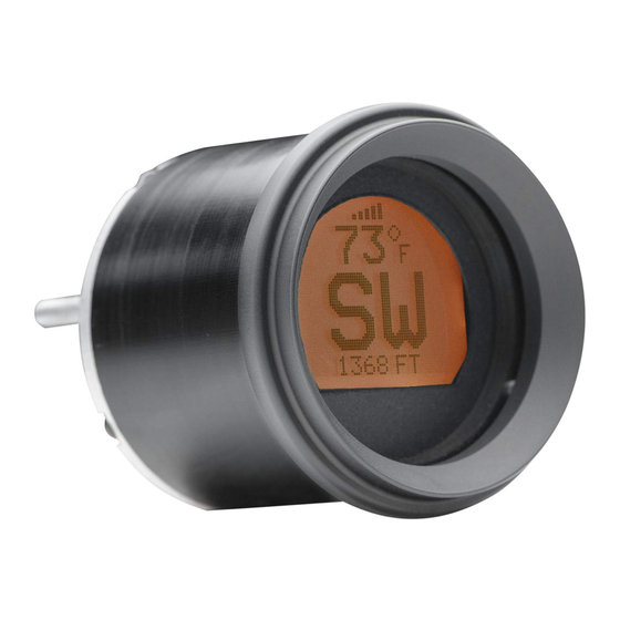
GAUGE FEATURES:
1
2
3
4
1.
Signal indicator
2.
Temperature reading
3.
Heading reading
4.
Message center
5.
Switch connector
6.
Gauge connector
Installation AND OPERATION MANUAL
MCH-GPS17
GPS Compass and Ambient Temperature Gauge
WIRE TIES (x6)
FRONT
shows the strength of the received GPS signal
displays the temperature read from the sensor
displays the direction the gauge is moving in
can be set to display altimeter, clock or toggle between both readings
location to connect switch for use in gauge setup
location to connect stock gauge harness for gauge power and temp sensor
FOR
NUTS (x3)
6
REAR
1
MANUAL (x1)
+12V
TEMP
SENSOR
GND
MAN # 650466
Advertisement
Table of Contents

Related Manuals for Dakota Digital MCH-GPS17


Summary of Contents for Dakota Digital MCH-GPS17
- Page 1 INSTALLATION AND OPERATION MANUAL MCH-GPS17 GPS Compass and Ambient Temperature Gauge KIT INCLUDES: MCH-GPS17 GAUGE (x1) MANUAL (x1) SWITCH (x1) NUTS (x3) WIRE TIES (x6) GAUGE FEATURES: +12V TEMP SENSOR FRONT REAR Signal indicator shows the strength of the received GPS signal...
- Page 2 INSTALLATION: Remove the outer fairing and the factory Air Temp gauge. This will vary by model; please follow the service manual to expose the wiring and gauges. Don’t be alarmed by the amount of wires behind the fairing, this is a direct plug in kit and these detailed instructions will guide you through installation.
- Page 3 OPERATION: HOW IT WORKS: The MCH-GPS17 uses the same GPS (Global Positioning System) signals that many common navigation systems use to determine location in the world. This location data is used to determine your motorcycle’s direction of travel. Altimeter (height above sea-level) and time data is also available from these signals and either or both can be displayed on the MCH-GPS17.
- Page 4 SETUP: ENTERING SETUP: 1. The supplied switch must be connected to the switch connector on the back of the gauge. 2. Press and hold the switch while turning on the motorcycle key, powering up the gauge. 3. The screen will display “SETUP”. Release the switch to enter the setup menu. USING SETUP MENU: 4.
- Page 5 Any action for breach of any warranty hereunder, including any implied warranty of merchantability, must be brought within a period of 24 months from date of original purchase. No person or representative is authorized to assume, for Dakota Digital, any liability other than expressed herein in connection with the sale of this product.
- Page 6 Screen reads “INTERNAL Internal battery needs The internal battery is not user serviceable. BATTERY VOLTAGE IS replacement or service. Contact Dakota Digital for an RMA number to LOW” even after several have the battery serviced. longer rides. Screen reads “LOCATING ”...
Need help?
Do you have a question about the MCH-GPS17 and is the answer not in the manual?
Questions and answers