Table of Contents
Advertisement
For 2003 and earlier Harley Davidson models with "fat bob" style tank-mount instrument
The MLX-2000 kit includes:
MLX display
*To avoid damage to motorcycle, please see Speedometer, Tachometer, and Status and Warning Indicators sections
for details on locating VSS, Tachometer, and indicator wires for most motorcycle applications
This gauge has an odometer preset option that is only available for the first 100 miles (160km) of
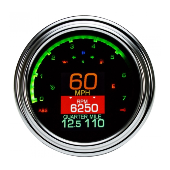
TANK MOUNT 5" SPEEDOMETER/TACHOMETER
IMPORTANT NOTE!
operation. See "preset odometer" on page 11 for instructions.
MLX-2000
Foam tape
Rubber studs
#8-32 nuts
Sensor harness
Main harness
1
Deuce mount
MAN# 650665:A
MBM
harness
8-32 x ½"
screws
#8 Lock
washers
#L-brackets
Speed harness
Advertisement
Table of Contents

Related Manuals for Dakota Digital MLX-2000


Summary of Contents for Dakota Digital MLX-2000
- Page 1 MLX-2000 TANK MOUNT 5” SPEEDOMETER/TACHOMETER For 2003 and earlier Harley Davidson models with “fat bob” style tank-mount instrument The MLX-2000 kit includes: Deuce mount Foam tape harness 8-32 x ½” screws #8 Lock washers #L-brackets Rubber studs #8-32 nuts MLX display...
-
Page 2: Gauge Installation
The MLX-2000 can be used in a variety of tank-mount dashes, including clip-in (1995 and newer), older bolt-in style, and the Deuce dash. The supplied L-brackets are used for the clip in version while the rubber mounts with studs on both sides are used for the bolt-in style. - Page 3 6. Tighten the screws. 7. If you’d like to add standard indicators, oil pressure, oil temperature, air pressure, boost or compass readings to the MLX-2000, connect the applicable harnesses and route to their appropriate locations; MBM modules may fit under the seat.
- Page 4 2. Unclip and unplug the factory gauge 3. Remove the rubber gasket from the factory gauge bezel. 4. Fit the gasket over the bezel of the MLX-2000. Only the inner, raised portion of the front bezel will be exposed while the entire back of the bezel is covered by the gasket.
-
Page 5: Wiring Diagram
OPTIONAL OIL TEMPERATURE Dakota Digital part number SEN-1043 or SEN-1044 must be used. The SEN-1043 is a one-wire sender with 1/8” NPT threads. Connect the terminal on the end of the sender to the indicator harness BLUE wire. Because this sensor grounds through its body, ensure sure the sender threads are able to make a metal-to-metal connection to complete the ground. - Page 6 RED – power, BLACK – ground, WHITE – speed signal. Connect the sensor signal wire to the MLX-2000 main harness GRAY wire, connect the sensor power wire to the WHITE/PURPLE wire, and connect the sensor ground wire to the WHITE/BLACK wire.
-
Page 7: System Features
System features INDICATORS Neutral High beam (green) (blue) Left turn Right turn (green) (green) Low oil (red) Cruise control Check engine (green/red) (red) Security (red) LOCATIONS There are two message locations available to display additional information under the speedometer. They are labeled Top and Bottom Message Location, respectively. -
Page 8: Function Switch
Operation, Clock Set, Service Reset FUNCTION SWITCH The factory trip reset switch on the side of the dash is used as the main function switch. During normal operation, the function switch allows access to information including mileage, RPM, and performance data located within two message locations below the speedometer. - Page 9 Programming SETUP MENU *To simplify the setup procedure, please download our IOS or Android app ‘Dakota Digital Motorcycle’* The function switch is used to enter setup mode. To get into setup, press and hold the function switch while turning the key on.
-
Page 10: Exiting Setup
Setup PRESS AND HOLD FUNCTION SWITCH WHILE TURNING IGNITION ON. Release the switch. For speed calibration: HOLD THE FUNCTION SWITCH WHILE STARTING THE BIKE Press and release the switch to move through the different setup menus. Press and hold the switch to enter a setup menu. Press and hold to also save an option. - Page 11 SPEED Speed setup menu • >> Speed calibration requires holding the function switch, THEN starting the engine << • When “>SPEED” is displayed, hold until “RELEASE” is displayed, and release the switch. • The selectable options are “ADJUST”, “AUTO”, “UNIT”, “SERVICE RESET”, “ODO PRESET”, or “BACK”. •...
- Page 12 The display options are “SEN-1043”, “SEN-1044” and “BACK”. • Press and release the switch to match to the optional sender you purchased from Dakota Digital. • Press and hold the switch on the selection, until “RELEASE” is displayed, and release.
- Page 13 OIL PSI Engine oil temperature setup menu • Only valid when optional SEN-1039 pressure sender is purchased from Dakota Digital. • When “>OIL PSI” is displayed, press and hold the switch until “RELEASE” is displayed, and release. • The options are “ON”, “OFF”, and “BACK”.
-
Page 14: Factory Reset
GEAR Gear indicator setup Optional gear readout could be displayed to the left of the clock only. Nothing will show until programming is done. The gear programming cannot take place until the speed is calibrated. The gauge can ‘learn’ the gear ratios based on speed and RPM, no additional sensors are needed. It will work with various transmissions up to seven speed models. -
Page 15: Troubleshooting Guide
Troubleshooting guide Problem Possible cause Solution Gauge will not light up White/Red wire does not have power. Connect to a location that has constant, battery power. Red wire does not have power. Connect to a location that has power with the key on. Black wire is not getting a good ground. -
Page 16: Service And Repair
DAKOTA DIGITAL warrants to the ORIGINAL PURCHASER of this product that should it, under normal use and condition, be proven defective in material or workmanship within 24 MONTHS FROM THE DATE OF PURCHASE, such defect(s) will be repaired or replaced at Dakota Digital’s option. This warranty does not cover nor extend to damage to the vehicle’s systems and does not cover removal or reinstallation of the product.
Need help?
Do you have a question about the MLX-2000 and is the answer not in the manual?
Questions and answers