Dakota Digital VHX systems Operating Manual
Clock / auxiliary displays for vhx systems
Hide thumbs
Also See for VHX systems:
Table of Contents
Advertisement
Quick Links
The VHX auxiliary display module is designed to work with a Dakota Digital VHX system and will not function properly
on its own. With this module, an additional display area is added to your current system to provide more functionality.
This module can be used as a simple clock display or it can display data from any BIM module attached to the system
as well as several gauge values from the control box sensors.
Most versions of this module come with at least one switch in the face to allow the display to change between various
Screens. Some versions may also contain two additional switches in the face which can be used as the SW1 and SW2
for the VHX control box with the use of the switch harness provided with it.
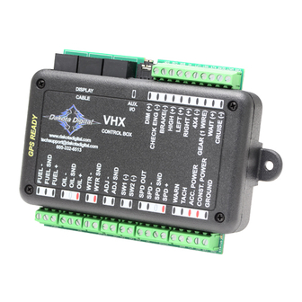
CONNECTION:
The auxiliary display has a connector on the rear that will accept a normal CAT 5, CAT 5E, or CAT 6 patch cable.
This can be used to connect the module to any available port on the VHX control box (same locations the main
VHX gauges plug into).
Auxiliary Display module
OR
SWITCH HARNESS:
Some auxiliary modules will come with the
pictured switch harness to allow additional
switches in the clock face to function as switch
1 and 2 for the main VHX system.
Auxiliary modules with 3 switches on front:
Connect the orange wire to SW1(-) terminal on VHX control box. Right switch will be SW1 (speed display).
Connect the green wire to SW2(-) terminal on VHX control box. Left switch will be SW2 (tach display).
Leave blue wire unconnected. Center switch will be SW3 (clock display)
Auxiliary modules with no switches on front:
If the module has no switches, connect an external switch from the blue wire of the harness to ground to allow
switch operations for the clock display. The orange and green wires would be left unconnected in this case.
Operating Manual for
Clock / Auxiliary Displays for VHX systems
Connection for all
auxiliary displays
Used for displays
with 3 switches
VHX
control
DISPLAY
CABLE
box
www.dakotadigital.com
techsupport@dakotadigital.com
605-332-6513
ORANGE
1
Use any open jack
AUX.
I/O
VHX
CONTROL BOX
GREEN
ORANGE (switch 1)
GREEN (switch 2)
BLUE (switch 3)
MAN #650360
Advertisement
Table of Contents

Related Manuals for Dakota Digital VHX systems


Summary of Contents for Dakota Digital VHX systems
- Page 1 Clock / Auxiliary Displays for VHX systems The VHX auxiliary display module is designed to work with a Dakota Digital VHX system and will not function properly on its own. With this module, an additional display area is added to your current system to provide more functionality.
- Page 2 SETUP: To enter setup, press and hold the switch (for systems with 3 switches, hold the center switch) while turning on the key. The display will read “SETUP”. Release the switch and the setup menu will be entered. Below is an outline of the setup options.
- Page 3 TEMP UNIT: This setting determines which temperature unit is used when displaying temperatures. This unit setting will be independent of the units used in the main VHX system and may be used to provide and alternate display unit from the main VHX screens if so desired. Default setting is Fahrenheit. Enter setup.
- Page 4 The main VHX system clock is only a 12hr clock. If a 24 hour clock display is desired, a BIM-16 clock expansion module may be purchased from Dakota Digital. This module will connect to the BIM expansion jack of the VHX control box and can be set in the main system setup.
- Page 5 CONTROL CHECK CONNECTIONS AND FOR BROKEN WIRES’” for repeatedly displays mode. solutions to the no data problem. “DAKOTA DIGITAL” VHX system is in demo mode This module will enter demo mode if the VHX system is in demo mode. Display is very dark or light Contrast needs to be adjusted See “SETUP”...
- Page 6 Dakota Digital’s option. This warranty does not cover nor extend to damage to the vehicle’s systems, and does not cover removal or reinstallation of the product.
Need help?
Do you have a question about the VHX systems and is the answer not in the manual?
Questions and answers