
Related Manuals for Dell PowerEdge XR8620t


Summary of Contents for Dell PowerEdge XR8620t
- Page 1 Dell PowerEdge XR8620t Installation and Service Manual Regulatory Model: E08B Regulatory Type: E08B001 May 2023 Rev. A00...
- Page 2 A WARNING indicates a potential for property damage, personal injury, or death. © 2023 Dell Inc. or its subsidiaries. All rights reserved. Dell Technologies, Dell, and other trademarks are trademarks of Dell Inc. or its subsidiaries. Other trademarks may be trademarks of their respective owners.
-
Page 3: Table Of Contents
Contents Chapter 1: About this document....................6 Chapter 2: Dell PowerEdge XR8620t system configurations and features ........7 System configurations - front view for PowerEdge XR8620t................. 7 System configurations - rear view for PowerEdge XR8620t..................10 System configurations - inside view for PowerEdge XR8620t................11 Locating the Express Service Code and Service Tag.................... - Page 4 iDRAC Settings................................45 Device Settings................................45 Chapter 7: Minimum configuration to POST ................46 Chapter 8: Installing and removing system components ..............47 Safety instructions................................47 Before working inside your system ..........................47 After working inside your system..........................47 XR8000r chassis................................48 Removing a sled blank..............................48 Installing a sled blank..............................
- Page 5 Chapter 10: Using system diagnostics..................105 Dell Embedded System Diagnostics..........................105 Running the Embedded System Diagnostics from Boot Manager..............105 Running the Embedded System Diagnostics from the Dell Lifecycle Controller........105 System diagnostic controls............................. 106 Chapter 11: Getting help......................107 Recycling or End-of-Life service information......................107 Contacting Dell Technologies............................
-
Page 6: Chapter 1: About This Document
About this document This document provides an overview about the system, information about installing and replacing components, diagnostic tools, and guidelines to be followed while installing certain components. About this document... -
Page 7: Chapter 2: Dell Poweredge Xr8620T System Configurations And Features
● 2 x M.2 2280 or 22110 direct connect NVMe drives on dual M.2 NVMe direct riser module (non-RAID) CAUTION: Do not install GPUs, network cards, or other PCIe devices on your system that are not validated and tested by Dell. Damage caused by unauthorized and invalidated hardware installation will null and void the system warranty. Topics: •... - Page 8 NOTE: If the server stops responding during POST, press and hold the System ID button for more than five seconds to enter the BIOS progress mode. Dell PowerEdge XR8620t system configurations and features...
- Page 9 RJ-45 dedicated port Enables you to remotely access iDRAC. For more information, see the Integrated Dell Remote Access Controller User's Guide at www.dell.com/ poweredgemanuals. Dell PowerEdge XR8620t system configurations and features...
-
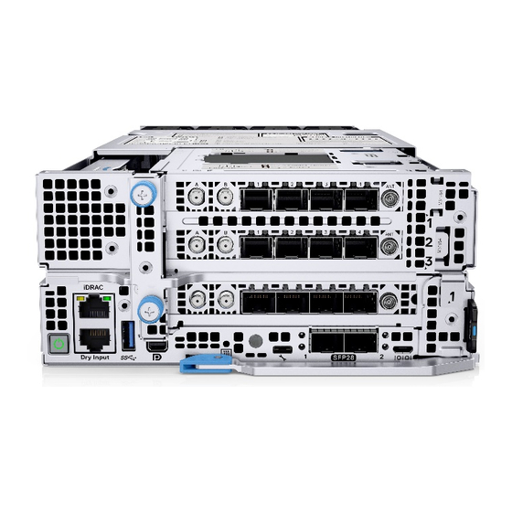
Page 10: System Configurations - Rear View For Poweredge Xr8620T
System configurations - rear view for PowerEdge XR8620t Figure 2. Rear view for PowerEdge XR8620t Table 2. Rear view of the sled Item Ports, panels, or slots Icon Description Upper layer 2U guiding pin Guiding pin for the 2U sled. -
Page 11: System Configurations - Inside View For Poweredge Xr8620T
System configurations - inside view for PowerEdge XR8620t Figure 3. Inside view of the PowerEdge XR8620t sled 1. 2U Power Distribution Board (PDB) 2. System Board 3. Riser 1 4. M.2 Direct Riser 5. Processor 6. 2U sled cooling fan Locating the Express Service Code and Service Tag The unique Express Service Code and Service Tag are used to identify the system. -
Page 12: System Information Label
2. iDRAC MAC address information label 3. Information tag (left view) 4. Express Service Tag label and QRL System information label The system information label is located on the back of the system cover. Figure 5. Service information Dell PowerEdge XR8620t system configurations and features... - Page 13 Figure 6. Memory information Figure 7. Jumper information Figure 8. Jumper settings Dell PowerEdge XR8620t system configurations and features...
-
Page 14: Chapter 3: Technical Specifications
• Ports and connectors specifications • Video specifications • Environmental specifications Sled dimensions Figure 9. Sled dimensions Table 3. PowerEdge XR8620t sled dimensions Z (handle closed). 184.8 mm (7.28 inches) 83.28 mm (3.28 inches) 433.5 mm (17.07 inches) Technical specifications... -
Page 15: System Weight
Generation Intel Xeon Scalable processors with up to 32 cores Cooling fan specifications The PowerEdge XR8620t system supports up to eight cabled cooling fans for airflow. Supported operating systems The PowerEdge XR8620t system supports the following operating systems: ● Red Hat Enterprise Linux ●... -
Page 16: Expansion Card Riser Specifications
Full Height Half Length x16 PCIe (Gen 5) Drives The PowerEdge XR8620t system supports 2 x M.2 NVMe SSDs (M.2 2280 and M.2 22110) on the M.2 riser. Ports and connectors specifications USB ports specifications Table 9. PowerEdge XR8620t USB specifications... -
Page 17: Display Port
The PowerEdge XR8620t system supports One Mini-DisplayPort on front of the system. iDRAC9 port specifications The PowerEdge XR8620t system supports one RJ45 with port status LEDs for iDRAC remote management (dedicated port only) on front of the system. RJ-45 dry contact port The PowerEdge XR8620t system supports 1 x RJ45 for dry contact on front of the system. -
Page 18: Video Specifications
Severity -3 (Info) is transitioned to Close state. Video specifications The PowerEdge XR8620t system supports integrated Matrox G200 graphics controller embedded in the iDRAC (BMC) chip with 16 MB of video frame buffer. Table 11. Supported video resolution options Resolution... - Page 19 Table 12. Continuous operation specifications for ASHRAE A2 (continued) Feature Allowable continuous operations Humidity percent range (non-condensing at all 8% RH with -12°C minimum dew point to 80% RH with 21°C (69.8°F) times) maximum dew point Operational altitude de-rating Maximum temperature is reduced by 1°C/300 m (33.8°F/984 Ft) above 900 m (2953 Ft) Table 13.
-
Page 20: Environmental Considerations
Table 17. Maximum vibration specifications Maximum vibration Specifications Operating 0.21 G at 5 Hz to 500 Hz (all operation orientations) Storage 1.88 G at 10 Hz to 500 Hz for 15 minutes (all six sides tested) Table 18. Maximum shock pulse specifications Maximum shock pulse Specifications Operating... -
Page 21: Thermal Restriction Matrix
50°C) 55°C) M.2 22110/2280 Max. 1.92T capacity support up to 55°C PCIe COMM Card Non-Dell qualified PCIe card is not supported NOTE: Do not perform a cold startup below 5°C. Other Restrictions ● Hot-swap fan is not supported. ● Support operation temperature -5°C~55°C. - Page 22 ● PSU blank is required in empty slots. Technical specifications...
-
Page 23: Chapter 4: Initial System Setup And Configuration
Initial system setup and configuration This section describes the tasks for initial setup and configuration of the Dell system. The section also provides general steps to set up the system and the reference guides for detailed information. Topics: • Setting up the system •... -
Page 24: Options To Log In To Idrac
Ensure that you change the default username and password after setting up the iDRAC IP address. For more information about logging in to the iDRAC and iDRAC licenses, see the latest Integrated Dell Remote Access Controller User's Guide available at https://www.dell.com/idracmanuals.. -
Page 25: Options To Download Drivers And Firmware
You can also access iDRAC using command-line protocol - RACADM. For more information, see the Integrated Dell Remote Access Controller RACADM CLI Guide available at https://www.dell.com/idracmanuals. You can also access iDRAC using automation tool - Redfish API. For more information, see the Integrated Dell Remote Access Controller User's Guide Redfish API Guide available at https://developer.dell.com. -
Page 26: Chapter 5: Resources To Install Operating System
Dell Lifecycle Controller User's Guide, go to https://www.dell.com/poweredgemanuals > Product Support page of your system > Documentation. Dell recommends using Lifecycle Controller to install the OS, since all required drivers are installed on the system. NOTE: To determine the most recent iDRAC release for your platform and for latest documentation version, see KB article at https://www.dell.com/support/article/sln308699. -
Page 27: Downloading Drivers And Firmware
Ensure that you clear the web browser cache before downloading the drivers and firmware. Steps 1. Go to www.dell.com/support/drivers. 2. Enter the Service Tag of the system in the Enter a Dell Service Tag, Dell Product ID or Model field, and then press Enter. NOTE: If you do not have the Service Tag, click Browse all products, and navigate to your product. -
Page 28: Chapter 6: Pre-Operating System Management Applications
UEFI (Unified Extensible Firmware Interface). You can enable or disable various iDRAC parameters by using the iDRAC settings utility. For more information about this utility, see Integrated Dell Remote Access Controller User’s Guide at www.dell.com/ poweredgemanuals. -
Page 29: System Bios
Table 28. System Setup Main Menu (continued) Option Description Service Tag Settings Enables you to configure the System Service Tag. System BIOS To view the System BIOS screen, power on the system, press F2, and click System Setup Main Menu > System BIOS. Table 29. - Page 30 Table 30. System Information details (continued) Option Description System CPLD Version Specifies the current version of the system Complex Programmable Logic Device (CPLD) firmware. UEFI Compliance Version Specifies the UEFI compliance level of the system firmware. Memory Settings To view the Memory Settings screen, power on the system, press F2, and click System Setup Main Menu > System BIOS >...
- Page 31 Table 31. Memory Settings details (continued) Option Description When option is set to Enable, the system performs the force full memory training steps on every power on and boot time is slowed on every boot. DIMM Self Healing (Post Package Repair) on Enables or disables Post Package Repair (PPR) on uncorrectable memory Uncorrectable Memory Error error.
- Page 32 Enables or disables AVX ICCP Pre-Grant License. This option is set to Disabled by default. Dell Controlled Turbo Dell Controlled Turbo Setting Controls the turbo engagement. Enable this option only when System Profile is set to Performance or Custom, and CPU Power Management is set to Performance.
- Page 33 Enables you to configure the Dell AVX scaling technology. This option is set to 0 by default. Enter the value from 0 to 12 bins. The value that is entered decreases the Dell AVX Scaling Technology frequency when the Dell-controlled Turbo feature is enabled.
- Page 34 RAID mode by default. BIOS NVMe Driver Dell Qualified NVMe drives always use the UEFI NVMe driver built into the Dell BIOS. When this option is set to All Drives, the BIOS driver will also be used with any NVMe drives in the system that has not been qualified by Dell.
- Page 35 NVMe-oF Host NQN This field specifies the name of the NVMe-oF host NQN. Allowed input is in the following format: nqn.yyyy-mm.<Reserved Domain Name>:<Unique String>. Leave it empty to use system generated value with following format: nqn.1988-11.com.dell:<Model name>.<Model number>.<Service Pre-operating system management applications...
- Page 36 Table 37. Network Settings details (continued) Option Description Tag>. This is set to nqn.1988-11.com.dell:<model name>.<model number>.<service tag> by default. NVMe-oF Host Id This field specifies a 16 bytes value of the NVMe-oF host identifier that uniquely identifies this host with the controller in the NVM subsystem.
- Page 37 Table 40. TLS Authentication Configuration screen details Option Description TLS Authentication Mode View or modify the device's boot TLS Authentication Mode. This option is set to One Way by default. None means the HTTP server and the client will not authenticate each other for this boot.
- Page 38 Table 44. NVMe-oF SubSystem Settings (continued) Option Description DHCP Enables and disables the DHCP for this NVMe-oF connection. This option is set to Disabled by default. Host IP Address Specifies the Host IP Address for this NVMe-oF connection. Host Subnet Mask Specifies the Host Subnet Mask for this NVMe-oF connection.
- Page 39 To view the Serial Communication screen, power on the system, press F2, and click System Setup Main Menu > System BIOS > Serial Communication. NOTE: The serial port is optional for the PowerEdge XR8620t system. The Serial Communication option is applicable only if the serial COM port is installed in the system. Pre-operating system management applications...
- Page 40 Table 46. Serial Communication details Option Description Serial Communication Enables the serial communication options. Selects serial communication devices (Serial Device 1 and Serial Device 2) in BIOS. BIOS console redirection can also be enabled, and the port address can be specified. The options available for System are On without Console Redirection, On with Console Redirection via COM1, On with Console Redirection via COM2...
- Page 41 Table 47. System Profile Settings details (continued) Option Description NOTE: All the parameters on the system profile setting screen are available only when the System Profile option is set to Custom. CPU Power Management Sets the CPU power management. This option is set to System DBPM (DAPC) by default. Other option includes Maximum Performance, OS DBPM.
- Page 42 Table 47. System Profile Settings details (continued) Option Description CPU Interconnect Bus Link Enables or disables the CPU Interconnect Bus Link Power Management. This option is set to Power Management Enabled by default. PCI ASPM L1 Link Power Enables or disables the PCI ASPM L1 Link Power Management. This option is set to Management Enabled by default.
- Page 43 Table 50. System Security details (continued) Option Description Pre-boot measurements. This option is set to Off by default. It is set On for Secure Launch (Firmware Protection) support. ® Memory Encryption Enables or disables the Intel Total Memory Encryption (TME) and Multi-Tenant (Intel TME-MT).
- Page 44 Table 50. System Security details (continued) Option Description Secure Boot Mode Configures how the BIOS uses the Secure Boot Policy Objects (PK, KEK, db, dbx). If the current mode is set to Deployed Mode, the available options are User Mode and Deployed Mode.
-
Page 45: Idrac Settings
NOTE: Accessing some of the features on the iDRAC settings needs the iDRAC Enterprise License upgrade. For more information about using iDRAC, see Dell Integrated Dell Remote Access Controller User's Guide at https:// www.dell.com/idracmanuals. -
Page 46: Chapter 7: Minimum Configuration To Post
Minimum configuration to POST The components listed below are the minimum configuration to POST: ● One processor (CPU) in socket processor ● Two memory module (DIMM) in socket A1 and A2 ● One power supply unit ● XR8000r chassis (Power Distribution Board, cables) ●... -
Page 47: Chapter 8: Installing And Removing System Components
Damage due to servicing that is not authorized by Dell is not covered by your warranty. Read and follow the safety instructions that are shipped with your product. -
Page 48: Xr8000R Chassis
Steps Reconnect the peripherals and connect the system to the electrical outlet, and then power on the system. XR8000r chassis Removing a sled blank Prerequisites Follow the safety guidelines listed in Safety instructions. Steps Pull the sled blank to remove it from the enclosure. Figure 12. -
Page 49: Removing A Sled
Figure 13. Installing a sled blank Removing a sled Prerequisites 1. Follow the safety guidelines listed in the Safety instructions. 2. Remove the front bezel, if applicable. Steps 1. Pull the blue lever on the sled to release the sled handle. 2. -
Page 50: Installing A Sled
Figure 14. Removing a sled from XR8000r Next steps Installing the sled Installing a sled Prerequisites Follow the safety guidelines listed in Safety instructions. Steps 1. Pull the blue lever on the sled to free the sled handle. 2. Holding the sled with both hands, align the sled along the sled-bay into the chassis. 3. -
Page 51: Sled Cover
Figure 15. Installing a sled into XR8000r Next steps Follow the procedure listed in After working inside your system. Sled cover Removing the sled cover Prerequisites 1. Follow the safety guidelines listed in the Safety instructions. 2. Power off the sled, and any attached peripherals. 3. -
Page 52: Installing The Sled Cover
Figure 16. Removing the sled cover Next steps Follow the procedure listed in Replace the sled cover. Installing the sled cover Prerequisites 1. Follow the safety guidelines listed in the Safety instructions. 2. Ensure that all internal cables are connected and routed properly, and no tools or extra parts are left inside the system. Steps 1. - Page 53 Figure 17. Installing the sled cover Next steps Follow the procedure listed in After working inside your system. Installing and removing system components...
-
Page 54: Air Shroud
Air shroud Removing the air shroud Prerequisites CAUTION: Never operate your system with the air shroud removed. The system may get overheated quickly, resulting in shutdown of the system and loss of data. 1. Follow the safety guidelines listed in the Safety instructions. -
Page 55: M.2 Direct Riser Module
Figure 19. Installing the air shroud Next steps Follow the procedure listed in After working inside your system. M.2 direct riser module Removing the M.2 direct riser module Prerequisites 1. Follow the safety guidelines listed in Safety instructions. 2. Follow the procedure listed in Before working inside your system. -
Page 56: Installing The M.2 Direct Riser Module
Figure 20. Removing the M.2 direct riser Next steps Replace the M.2 direct riser. Installing the M.2 direct riser module Prerequisites 1. Follow the safety guidelines listed in Safety instructions. 2. Follow the procedure listed in Before working inside your system. -
Page 57: Removing The M.2 Nvme Module From The M.2 Direct Riser Module
Figure 21. Installing the M.2 direct riser Next steps Follow the procedure listed in After working inside your system. Removing the M.2 NVMe module from the M.2 direct riser module Prerequisites 1. Follow the safety guidelines listed in Safety instructions. 2. -
Page 58: Installing The M.2 Nvme Module On The M.2 Direct Riser
Next steps Replace the M.2 NVMe module. Installing the M.2 NVMe module on the M.2 direct riser Prerequisites 1. Follow the safety guidelines listed in Safety instructions. 2. Follow the procedure listed in Before working inside your system. 3. Remove the latch on the snap clip and rotate the latch to a vertical position. NOTE: The position of the blue latch used for the M.2 2280 and M.2 22110 NVMe drives are different. -
Page 59: Installing The Side Cover
Steps 1. Using the Phillips 2 screwdriver, loosen the captive screws that secure the side cover to the 2U sled. 2. Slide the side cover outward to remove it from the sled. Figure 24. Removing the 2U side cover Next steps Remove the 2U floor from the 1U node. -
Page 60: Removing The 2U Floor From The 1U Node
Figure 25. Installing the 2U sled side cover Next steps Install the M.2 direct riser module. Removing the 2U floor from the 1U node Prerequisites 1. Follow the safety guidelines listed in Safety Instructions. 2. Follow the procedure listed in Before working inside your system Remove the air shroud. -
Page 61: Installing The 2U Floor On The 1U Node
Figure 26. Removing the 2U floor from the 1U node Next steps Replace the 2U floor on the 1U sled. Installing the 2U floor on the 1U node Prerequisites 1. Follow the safety guidelines listed in Safety Instructions. 2. Follow the procedure listed in Before working inside your system. -
Page 62: Storage Interposer Module
Figure 27. Installing the 2U floor on the 1U node Next steps Install the Riser Install the side cover Install the M.2 direct riser Install the 2U power distribution board. Install the 2U cooling fans. Install the air shroud. Storage interposer module Removing the storage interposer module Prerequisites 1. -
Page 63: Installing The Storage Interposer Module
Figure 28. Removing the storage interposer module 2. Lift the board to remove it from the system. Next steps Replace the storage interposer module. Installing the storage interposer module Prerequisites 1. Follow the safety guidelines listed in Safety instructions. 2. Follow the procedure listed in Before working inside your system. -
Page 64: Cooling Fans
Figure 29. Installing the storage interposer module Next steps Install the M.2 direct riser module Cooling fans Removing a cooling fan on 2U sled Prerequisites 1. Follow the safety guidelines listed in Safety Instructions. 2. Follow the procedure listed in Before working inside your system. -
Page 65: Installing A Cooling Fan On 2U Sled
Figure 30. 2U sled fan cable routing 2. Pull slightly to disengage the fan cable from the fan guard and then lift the fan module out of the fan cage. NOTE: The airflow directional arrow outward on the fan indicates Reverse-Air-Flow (RAF). Figure 31. - Page 66 NOTE: Observe the fan cable routing or make a note of the fan cable routing. Steps 1. Lower the fan module into the cage until it is seated firmly. NOTE: The airflow directional arrow outward on the fan indicates Reverse-Air-Flow (RAF). Figure 32.
-
Page 67: Removing A Cooling Fan On 1U Sled
Removing a cooling fan on 1U sled Prerequisites 1. Follow the safety guidelines listed in Safety instructions. 2. Follow the procedure listed in Before working inside your system. Remove the 2U sled from 1U node. NOTE: Observe the fan cable routing or make a note of the fan cable routing. Steps 1. -
Page 68: Installing A Cooling Fan On 1U Sled
Next steps Replace a fan on 1U sled Install the 2U sled on 1U node Installing a cooling fan on 1U sled Prerequisites 1. Follow the safety guidelines listed in Safety Instructions. 2. Follow the procedure listed in Before working inside your system. -
Page 69: Expansion Cards And Expansion Card Risers
When an expansion card is not supported or missing, the iDRAC and Lifecycle Controller logs an event. This does not prevent your system from booting. However, if a F1/F2 pause occurs with an error message, see Troubleshooting expansion cards section in the PowerEdge Servers Troubleshooting Guide at www.dell.com/poweredgemanuals. Installing and removing system components... -
Page 70: Expansion Card Installation Guidelines
Expansion card installation guidelines Figure 38. Expansion card slot connector 1. Riser 1U connector(Riser 2) 2. Reserved (IO_RISER2) Figure 39. Riser 1A slots 1. Slot 1 2. Slot 2 Installing and removing system components... - Page 71 Figure 40. Riser 2A slot 1. Slot 3 Table 53. Riser Configurations Config # RSR Configuration # of CPUs PERC type Rear Storage x16 CPU1 X16 CPU2 supported Possible No riser R1A+R2A NOTE: The expansion-card slots are not hot-swappable. The following table provides guidelines for installing expansion cards to ensure proper cooling and mechanical fit. The expansion cards with the highest priority should be installed first using the slot priority indicated.
-
Page 72: Removing The Expansion Card Riser 1
Removing the expansion card riser 1 Prerequisites 1. Follow the safety guidelines listed in Safety instructions. 2. Follow the procedure listed in Before working inside your system. Remove the air shroud Remove the M.2 direct riser Remove the side cover 6. -
Page 73: Removing The Expansion Card Riser 2
2. Using both hands, lower the riser 1 until it is seated firmly. 3. Using a Phillips 2 screwdriver, tighten the captive screws to secure the expansion card riser 1 on to the 2U sled. Figure 42. Installing the expansion card riser 1 4. -
Page 74: Installing The Expansion Card Riser 2
Figure 43. Removing the expansion card riser 2 Next steps Replace the expansion card riser Installing the expansion card riser 2 Prerequisites 1. Follow the safety guidelines listed in Safety instructions. 2. Follow the procedure listed in Before working inside your system. -
Page 75: Removing The Pcie Card From Riser
Figure 44. Installing the expansion card riser 2 Next steps Install the 2U floor on the 1U node. Removing the PCIe card from Riser Prerequisites 1. Follow the safety guidelines listed in Safety instructions. 2. Follow the procedure listed in Before working inside your system. -
Page 76: Installing The Pcie Card On Riser
Figure 45. Removing the PCIe card from Riser 2. Replace the expansion card filler bracket. Figure 46. Installing the expansion card filler bracket Next steps Replace the PCIe card on Riser. Installing the PCIe card on Riser Prerequisites 1. Follow the safety guidelines listed in Safety instructions. - Page 77 Steps 1. Remove the expansion card filler bracket by sliding it out of the sled. Figure 47. Removing the expansion card filler bracket 2. Using both hands, insert the PCIe card into the riser slot till it clicks into place. Figure 48.
-
Page 78: Power Distribution Board
Power distribution board This is a service technician replaceable part only. Removing the 2U power distribution board Prerequisites 1. Follow the safety guidelines listed in Safety instructions. 2. Follow the procedure listed in Before working inside your system. Remove the air shroud. -
Page 79: Removing The 1U Power Distribution Board
2. Follow the procedure listed in Before working inside your system. Remove the air shroud. Remove the Riser Steps 1. Align the slots of the Power distribution board (PDB) with the fix hook on the 2U sled. 2. Using a Phillips 2 screwdriver, tighten the screws to secure the PDB on the 2U sled. Figure 50. -
Page 80: Installing The 1U Power Distribution Board
Figure 51. Removing the 1U power distribution board 2. Lift the board to remove it from the system. Next steps Replace the 1U power distribution board. Installing the 1U power distribution board Prerequisites 1. Follow the safety guidelines listed in Safety instructions. -
Page 81: Cable Routing
Figure 52. Installing the 1U power distribution board Next steps 1. Connect the cables connected from cooling fans and system board to the 1U power distribution board (PDB). Install the Riser 2 Install the 2u floor on the 1u node Cable routing Figure 53. -
Page 82: System Memory
NC-SI (NC-SI Connector) System memory System memory guidelines The PowerEdge XR8620t system supports DDR5 registered DIMMs (RDIMMs). System memory holds the instructions that are executed by the processor. Your system memory is organized into eight channels(one memory slot per channel). - Page 83 Figure 54. Memory channels Memory channels are organized as follows: Table 57. Memory channels Processor Channel Channel B Channel C Channel D Channel E Channel F Channel G Channel H Processor Slots A1 Slots A7 Slots A3 Slots A5 Slots A4 Slots A6 Slots A2 Slots A8...
-
Page 84: General Memory Module Installation Guidelines
General memory module installation guidelines To ensure optimal performance of your system, observe the following general guidelines when configuring your system memory. If your system's memory configuration fails to observe these guidelines, your system might not boot, stop responding during memory configuration, or operate with reduced memory. -
Page 85: Installing A Memory Module
Figure 55. Removing a memory module Next steps Installing the memory module. 2. If you are removing the memory module permanently, install a memory module blank. The procedure to install a memory module blank is similar to that of the memory module. Installing a memory module Prerequisites 1. -
Page 86: Processor And Heat Sink Module
Figure 56. Installing a memory module Next steps 1. Follow the procedure listed in After working inside your system. 2. To verify if the memory module has been installed properly, press F2 and navigate to System Setup Main Menu > System BIOS >... - Page 87 NOTE: Ensure that the anti-tilt wires on the PHM are in locked position when loosening the captive nuts. 2. Set all the anti-tilt wires to unlocked position (inward position). Figure 57. Removing the processor heat sink module 3. Lift the PHM from the system and set the PHM aside with the processor side facing up. Figure 58.
-
Page 88: Removing The Processor
Next steps If you are removing a faulty heat sink, replace the heat sink, if not, remove the processor. Removing the processor Prerequisites WARNING: Remove the processor from processor and heat sink module (PHM) only if you are replacing the processor or heat sink. -
Page 89: Installing The Processor
Figure 60. Removing the retaining clip Next steps Replace the processor. Installing the processor Prerequisites 1. Follow the safety guidelines listed in the Safety instructions. 2. Follow the procedure listed in Before working inside your system. Remove the 2U sled from 1U node Remove the processor. - Page 90 Figure 61. Installing the retaining clip 3. Align the processor with retaining clip, by using your fingers press the retaining clip on all the four sides until it clicks into place. NOTE: Ensure that the processor is securely latched to the retaining clip. Figure 62.
- Page 91 NOTE: The thermal grease syringe is intended for single use only. Dispose the syringe after you use it. Figure 63. Applying thermal grease 6. For new heat sink, pull and remove the plastic cover from the base of heat sink. Figure 64.
-
Page 92: Installing The Processor And Heat Sink Module
Figure 65. Installing the heat sink onto the processor Next steps Install the processor heat sink module. Install the 2U sled on 1U node 3. Follow the procedure listed in After working inside your system. Installing the processor and heat sink module Prerequisites Never remove the heat sink from a processor unless you intend to replace the processor or heat sink. - Page 93 Figure 66. Installing the processor heat sink 3. Set the anti-tilt wires to the locked position (outward position), and then using the Torx T30 screwdriver, tighten the captive nuts (8 in-lbf) on the heat sink in the order below: a. In a random order, tighten the first nut three turns. b.
-
Page 94: System Battery
Figure 67. Set the anti-tilt wires to the locked position and tightening the nuts Next steps Install the 2U sled on 1U node 2. Follow the procedure listed in the After working inside your system. System battery This is a service technician replaceable part only. Replacing the system battery Prerequisites WARNING:... - Page 95 Figure 68. Removing the system battery 2. To install a new system battery: a. Hold the battery with the positive side facing up and slide it under the securing tabs. b. Press the battery into the connector until it snaps into place. Figure 69.
-
Page 96: System Board
c. Exit the System Setup. d. To test the newly installed battery, remove the system from the enclosure for at least an hour. e. Reinstall the system into the enclosure after an hour. f. Enter the System Setup and if the time and date are still incorrect, see Getting help section. -
Page 97: Installing The System Board
Figure 70. Removing the system board Next steps Installing the system board. Installing the system board Prerequisites NOTE: Before replacing the system board, replace the old iDRAC MAC address label in the Information tag with the iDRAC MAC address label of the replacement system board 1. - Page 98 4. If you are not using Easy Restore, import your new or existing iDRAC Enterprise license. For more information, see the Integrated Dell Remote Access Controller User's Guide available at https://www.dell.com/idracmanuals. 5. Follow the procedure listed in After working inside your system.
-
Page 99: Trusted Platform Module
Restoring the system using Easy Restore The Easy Restore feature enables you to restore your service tag, license, UEFI configuration, and the system configuration data after replacing the system board. All data is backed up in a backup flash device automatically. If BIOS detects a new system board, and the service tag in the backup flash device, BIOS prompts the user to restore the backup information. -
Page 100: Initializing Tpm For Users
CAUTION: The TPM plug-in module is cryptographically bound to that particular system board after it is installed. When the system is powered on, any attempt to remove an installed TPM plug-in module breaks the cryptographic binding, and the removed TPM cannot be installed on another system board. Ensure any keys you have stored on the TPM have been securely transferred. -
Page 101: Initializing The Tpm 2.0 For Users
Initializing the TPM 2.0 for users Steps 1. While booting your system, press F2 to enter System Setup. 2. On the System Setup Main Menu screen, click System BIOS > System Security Settings. 3. From the TPM Security option, select On. 4. -
Page 102: Chapter 9: Jumpers And Connectors
Jumpers and connectors This topic provides some basic and specific information about jumpers and switches. It also describes the connectors on the various boards in the system. Jumpers on the system board help to disable the system and reset the passwords. To install components and cables correctly, you must know the connectors on the system board. -
Page 103: System Board Jumper Settings
Table 60. System board connectors description Item Connector Description SL4_CPU1_PA4 PCIe connector 4 SL3_CPU1_PB4 PCIe connector 3 SL2_CPU1_PB3 PCIe connector 2 SL1_CPU1_PA3 PCIe connector 1 J_R1_PWR PCIe Extension Power SYS_PWR_CONN1 Power connector 1 SYS_PWR_CONN2 Power connector 2 PIB Signal PIB Signal IO_RISER1 Riser 1 connector Reserved(INT_USB1) -
Page 104: Disabling A Forgotten Password
Damage due to servicing that is not authorized by Dell is not covered by your warranty. Read and follow the safety instructions that are shipped with your product. -
Page 105: Chapter 10: Using System Diagnostics
Using system diagnostics If you experience an issue with the system, run the system diagnostics before contacting Dell for technical assistance. The purpose of running system diagnostics is to test the system hardware without using additional equipment or risking data loss. -
Page 106: System Diagnostic Controls
System diagnostic controls Table 62. System diagnostic controls Menu Description Configuration Displays the configuration and status information of all detected devices. Results Displays the results of all tests that are run. System health Provides the current overview of the system performance. Event log Displays a time-stamped log of the results of all tests run on the system. -
Page 107: Chapter 11: Getting Help
Dell contact information on your purchase invoice, packing slip, bill or Dell product catalog. The availability of services varies depending on the country and product, and some services may not be available in your area. To contact Dell for sales, technical... -
Page 108: Quick Resource Locator For Poweredge Xr8620T System
Dell. This information is used by Dell Technical Support to troubleshoot the issue. ● Proactive contact — A Dell Technical Support agent contacts you about the support case and helps you resolve the issue. -
Page 109: Chapter 12: Documentation Resources
This section provides information about the documentation resources for your system. To view the document that is listed in the documentation resources table: ● From the Dell support site: 1. Click the documentation link that is provided in the Location column in the table. - Page 110 Table 63. Additional documentation resources for your system (continued) Task Document Location Managing your system For information about systems management www.dell.com/poweredgemanuals software offered by Dell, see the Dell OpenManage Systems Management Overview Guide. For information about setting up, using, www.dell.com/openmanagemanuals > and troubleshooting OpenManage, see the OpenManage Server Administrator Dell OpenManage Server Administrator User’s...
Need help?
Do you have a question about the PowerEdge XR8620t and is the answer not in the manual?
Questions and answers