
Related Manuals for Endress+Hauser asp-port d 2


Summary of Contents for Endress+Hauser asp-port d 2
- Page 1 Multi-function BA 038R/09/e/11.95 Part No. 50051409 water sampler asp-port d 2 Installation and operating instructions Endress Hauser Nothing beats know-how...
-
Page 3: Transport Insurance
Danger: Ignoring this warning can lead to personal injury. Should the "asp-port d 2" be in storage for more than 6 months please take note of the storage details in chapter "Maintenance, general". Please enter details here:... -
Page 4: Asp-Port D
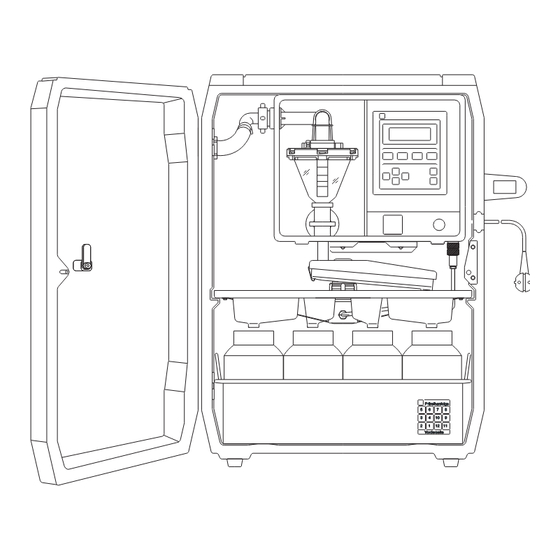
2 Dimensional drawing, complete unit 404.0 532.0 692.0 Sampler asp-port d 2 : 1 = Controller liqui-box d 2 2 = Cable entry 3 = Distribution system (tap, tray) 4 = Bottle tray with bottles and lids ©... -
Page 5: Table Of Contents
2 Contents Page Contents Please note: - Complete delivery - Transport insurance - Enter unit information asp-port d 2 - Dimensional drawing and complete construction Contents General notes - Safety Mechanical installation - General - Installation - Hose connection / installation... - Page 6 Contents asp-port d 2 Page Operating and display components - General - Operating components - Setting up principle - Short form instructions - Programme selection and information - Base settings - Programmes: Creating and changeover - Start/stop operation - Service level...
-
Page 7: General Notes
2 General notes This unit is constructed and tested according to EN 61010-1 / Safety VDE 0411 Part 1 and left our works in perfect and safe condition. In order to maintain this condition and operate safely the user must take note of the following safety information and warnings contained in these instructions. -
Page 8: Mechanical Installation
Mechanical installation asp-port d 2 General The water sampler must be installed so that it stands higher than the sampling point. It can be installed outside and mounted on a concrete foundation or solid level ground. The unit can be levelled by using the four levelling screws fitted in the bottom of the sampler. -
Page 9: Electrical Installation
2 Electrical installation Power supply Plug in the mains plug (female) on the mains cable to the controller socket C Mains version (AC) (male) and tighten the securing nut. Pull out rubber cable entry in housing wall and lay cable inside... -
Page 10: In And Outputs
Electrical installation asp-port d 2 In/outputs Signal socket connections (Signal socket E) White = Auxiliary voltage (-) 0V (common) Brown = Auxiliary voltage (+) 8 to 19 V output Green = Flow impulse input Yellow = External stop input Grey... -
Page 11: Inputs
2 Electrical installation Inputs 1 Impulse input (Pin 3, green). Max.25Hz (+7 to +27 Volt). Flow impulse inputs For connecting an external quantity measuring system 1 analogue input (current or voltage) Analogue flow input Pin 10 violet for negative input, pin 11 grey/pink 5 for positive input. -
Page 12: What Happens On Power Up
Electrical installation asp-port d 2 What happens on power up ? Power failures a) The unit runs a self check (start up). Display shows ”Unit OFF”. b) Short term power failures (<24 hrs) during automatic operation No samples are taken, the inputs are not interrogated, however, the internal clock continues to run during power failure. -
Page 13: Sampling Principle
2 Sampling principle Vacuum principle 1 The dosing system is 2 A fresh sample is then pneumatically sealed at the sucked into the dosing beginning of each sample chamber until the cycle. The diaphragm pump conductivity level switch is... -
Page 14: For First Installation
For first installation asp-port d 2 General The sampler is constructed for practical operation and can be applied virtually everywhere. In addition to the versatile setting up the operator also has the possibility to preset six individual programmes. These can be accessed at any time. - Page 15 00:00 bottle/container change Switch on/off fixed time base of bottles/containers "asp-port d 2" if fitted externally with 12 bottles and 2 hour filling time per Time synchronisation example: bottle. On synchronisation time of 00:00 (addr. 127) and switched on bottle synchronisation (addr.
-
Page 16: Setting Up Sample Volume
2 Varying sample volume Follow the next steps. 1. Open cabinet door 2. Switch unit off Operate the - OFF- (4) push button at the "asp-port d 2". Dosing system: = Elbow = Dosing tube = Dosing chamber = Piping clamp 3. - Page 17 2 Setting up sample volume Lift clamp from pipe elbow. 4. Remove dosing system Pull dosing system forwards and remove from controller. Release the bayonet fitting by turning the 5. Remove flange lower part of the flange as shown.
- Page 18 Setting up sample volume asp-port d 2 7. Replace dosing system = Nipple = Suction pipe elbow = Hose clamp = Contacts = Spring contacts = Fixing clamp = Silicon hose Push silicon hose into the hose clamp Push suction pipe elbow onto the nipple .
-
Page 19: Maintenance
This switch can be found on the CPU board next to the "data security accumulator" behind the controller front keypad and display plate. Should you need to return an asp-port d 2 or part of it to your Repairs Endress+Hauser service department for repair please take note of the following: Remove all deposits. -
Page 20: Operating And Display Components
Operation and display asp-port d 2 General Operating mode Actual display Selection menu (levels) 000 Programme select. + 100 Base settings 200 Set up programme + 300 Start/Stop operation 400 Service level Selected level ( Addresses ) Unlock Set up unit... -
Page 21: Operating Components
2 Operation and display "ON" Key activates the controller (liqui-box d 2). Operating components Display indicates ON with date and time. "OFF" Key switches the controller (liqui-box d 2) off. Display indicates OFF with date and time. An already started sample cycle is aborted (or completed if the suction phase has been reached). -
Page 22: Short Form Instructions
Operation and display asp-port d 2 Short form instructions for a The following addresses are important when changing the factory settings in swift start: a sample sequence programme: 1. Select level "Base settings", unlock security code (code 6051) Addr. 110: select and set up Addr. - Page 23 2 Operation and display This page was left empty for notes:...
-
Page 24: Programme Selection And Information
Operation and display asp-port d 2 Programme selection and information Programme Print select A parameters One, from programme 1 to 6 since: Yes or No date/time Power failures Power failure External stops External stop Control input Control input time, last:... - Page 25 2 Operation and display Adr. Description Works setting Sampling: 6 programmes are in memory. One out of six can be selected in this address. This programme will become active in automatic operating mode (after AUT has been operated).
-
Page 26: Base Settings
Operation and display asp-port d 2 Base settings Sample Bottle volume volume Set up Set up range: range: 0...500 ml 00,0...99,9 l Self Blow out time Suction time Dosing time Sample delay Conductivity Synchronisation Synchronisation Synchronisation optimising (Phase 1) (Phase 2) - Page 27 2 Operation and display Addr. Description Works settings Set up the same dosing volume as on the filling tube in the dosing chamber 300 ml Set up single bottle / container volume (-10% for safety) (Addr. 110/111 operate as bottle overfill security).
-
Page 28: Programmes: Creating And Changeover
Operation and display asp-port d 2 Programmes: Creating and changeover Sampling Time interval Sampling Sample Fill time per Samples per quantity distribution bottle bottle Progr. 1 Progr. 1 Progr. 1 Progr. 1 Progr. 1 Progr. 1 Time/ Range: Change on... -
Page 29: Start/Stop Operation
2 Operation and display Address Description Works settings Programme 1: (Select one from three possibilities) - Time proportional sampling: Samples are taken in even time cycles. Quantity proportional sampling: High flow = Many samples Timed Low flow = Few samples Condition: That a flow meter is connected to the sampler. - Page 30 Operation and display asp-port d 2 Start / stop operation Start/Stop Start/Stop- mode Reset to zero Continuous Once Daily Mo/Tue.. Sat/Sun Yes / no Start date Stop date Not active Not active Active = Active = Day, month, Day, month,...
- Page 31 2 Operation and display Address Description Works settings Select one from six possibilities: Continuous operation: Once the AUT push button has been operated the unit operates continuously with the preset programme (addresses 320 - 369 not active). Continuous...
-
Page 32: Service Level
Operation and display asp-port d 2 Service level Update Software Processor Service date report Abort counter Name and 3 digit version last fault Yes / no number 4 digit Sampler Pump Cooler Sample Electrode 2 Ack. without running time running time... -
Page 33: Operator Settings
2 Operation and display Address Description Date of last service. Must be set to "Yes" and initiated by sevice technician ! Please always indicate this value on any queries ! Sum of all faults that led to an abort. Last fault is indicated with an error code number. - Page 34 Operation and display asp-port d 2 User settings Date Name...
- Page 35 2 Operation and display User settings (Reserve table can be copied for multiple Date Name...
-
Page 36: Changing Analogue Input
Changing analogue input asp-port d 2 Works setting: current input The sampler is always delivered set on current input. Selection of 0 ...+20mA or +4 ...+20mA is done in address 141. There is no need to open the controller..change to voltage input: For special applications the controller can be set to a voltage input of 0 ...+1 Volt or 0 ...+10 Volt. -
Page 37: Sample Distribution Conversion
2 Sample distribution conversion The sampler can operate using a composite container or can distribute the Changing number of bottles samples into a number of descrete bottles using a sample distribution system. Changing from one form of distribution to another can be done by simply exchanging one form for another. -
Page 38: Problems And Solutions
Problems and solutions asp-port d 2 Fault messages The sampler contains a self monitoring function system. Faults occurring are displayed including a fault number as well as a hint as to how to remove the fault. Once the fault has been removed acknowledge this by operating the ON push button. -
Page 39: Spare Parts
2 Spare parts Description Order code Spare parts liqui-box d 2 control module... Complete control module (standard) RPF1D-1HA1 Complete control module (illuminated display) RPF1D-1HB1 Cabinet and external components: External elbow fitting 13 mm 50062334 + 50042066 External elbow fitting 15 mm... -
Page 40: Technical Data
Technical data asp-port d 2 Cabinet: Hard polyeurythane foam H x W x D approx. 725 x 532 x 400 mm Weight: Approx. 28 kg Protection class Controller (Keypad): IP 55 to DIN 40050 Allowable ambient temperature: Without heater +0°C ... +40 With heater -15°C ... - Page 41 2 Technical data 6 individual presettable programmes, presettable programme change Sampling modes: (switching) conditions (eg. Q-t changeover, Q-q changeover, etc.) Possibilities : Time proportional Quantity proportional Event controlled Manual start Individual start/stop operation using daily/weekday switch functions Timer...
- Page 42 Technical data asp-port d 2 Options: Battery pack in housing (12 2 x 6 Volt / 10 AH (12 VDC in series) VDC) W x H x D: approx 160 x 300 x 90 mm Approx 1.5 m connection cable to the "liqui-box d 2"...
- Page 44 Representations in Europe Austria France Poland Endress+Hauser Ges.m.b.H. Endress+Hauser DJ+UT Sp. z o.o., Reprezentant firmy Endress+Hauser Postfach 173, 3, Rue du Rhin, BP 150 ul. Rydygiera 8, 01-793 Warszawa 86 1235 Wien 68331 Huningue (Cedex) Tel. (02) 6 33 84 80, Telex 8 15 887, Fax (02) 6 33 84 92 Tel.
Need help?
Do you have a question about the asp-port d 2 and is the answer not in the manual?
Questions and answers