Vexve Hydrox HCU Remote Installation, Operation And Maintenance Instructions
Hide thumbs
Also See for Hydrox HCU Remote:
Table of Contents
Advertisement
Quick Links
Advertisement
Table of Contents

Subscribe to Our Youtube Channel
Related Manuals for Vexve Hydrox HCU Remote


Summary of Contents for Vexve Hydrox HCU Remote
- Page 1 Hydrox™ HCU Remote Installation, operation and maintenance instructions...
-
Page 2: Table Of Contents
8.3. WebApp remote control 5.2.4. To stop valve moment 9. Troubleshooting 5.2.5. Local control buttons 5.2.6. Remote control buttons 5.2.7. Position indication 5.3. Using the manual pump 5.3.1. Opening the valve 5.3.2. Closing the valve 5.3.3. To stop the valve moment www.vexve.com... -
Page 3: Safety Instructions
1. Safety instructions Note Danger Harmful / irritating Use safety glasses Use protective footwear Use ear protection Use protective gloves Use protective clothing Use safety helmet Read user manual www.vexve.com... - Page 4 Oil jet hazard Never handle pressurized hydraulic hoses and similar components with bare hands, since high-pressure leaks may penetrate the skin. Always wear eye protection, particularly when working with systems in operation. www.vexve.com...
- Page 5 When the system is again under pressure, the repaired system section must be tested. Check the system for possible leaks after repair. Do not tighten leaking couplings while the system is pressurized. www.vexve.com...
-
Page 6: Oil Storage And Handling
Used filters, research equipment, oil samples and waste oil must be handled in accordance with general and mill-specific instructions for handling of hazardous waste. Used filters and filter diaphragms used in analyses must be packed into containers. The containers must be marked in accordance with the ap- plicable instructions on hazardous waste. www.vexve.com... -
Page 7: General Information
· Do not ever leave any part of the hydraulic valves in order to heat up/cool down the system open to contamination to prevent components before use. Vexve does not take damage to the internal components. responsibility of any damage to the control ·... -
Page 8: Regular Inspections And Maintenance
When replacing the fitting and the pipe, they must be cleaned from the inside to be com- pletely free of all impurities, including burrs prior to insertion. Replacement must be carried out with absolute purity. www.vexve.com... -
Page 9: Hcu Remote Introduction
· Position indication: Diode indication for · Maximum recommended pressure 210 bar· position 0-100 % open and end positions · Pressure limiter 150 bar (adjustable) · Alarms: Active and old ones Oil reservoir · Diagnostics Capacity: 2 liters Pressure gauge · Range: 0…250 bar www.vexve.com... - Page 10 Hydrox Control Unit (HCU) Remote - 812012 Wireless remote control Hydrox Control Unit (HCU) Remote - 812013 For six valves Hydrox Control Unit (HCU) Remote - 812014 For two valves Hydrox Control Unit (HCU) Remote - 812015 Cooling Table 3. Options and product numbers www.vexve.com...
-
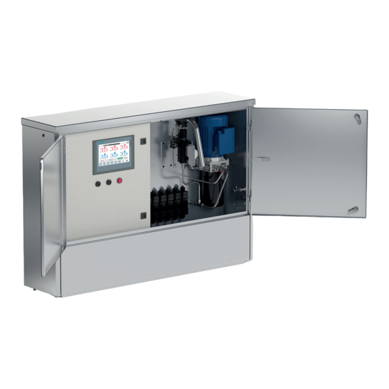
Page 11: Control Cabinet Overview
Figure 1. Cabinet overview Part Electrical cabinet Pressure transmitter (optional) Valve block Hand pump pressure adjustment Hand pump Electric Motor Hydraulic Pump System cabinet Safety valve Pressure gauge Oil reservoir Plinth (purchased separately) Table 4. Contents and componets of cabinet www.vexve.com... -
Page 12: Electrical Cabinet Overview
4.2. Electrical cabinet overview Figure 2. Electrical cabinet overview www.vexve.com... -
Page 13: Function Description
5. Function description 5.1. Overview The Hydrox HCU Remote is designed to control between 2 and 6 valves operated with hydraulic actuators and used in different applications. These actuators are operated by a semi-closed loop system which al- lows the operation of specific valves by opening/closing them in a controlled manner through the manipula- tion of oil pressure using an inverter-controlled pump. -
Page 14: Valve Selection
5.2.2. Opening the valve: Once the valve is selected, press the OPEN button. The pump starts to open the valve according to the configured operational behaviour curve (see section 7.2.3). The pump will automatically stop when the valve reaches the open position. www.vexve.com... -
Page 15: Closing The Valve
CLOSE STOP VALVE VALVE Figure 4. Local buttons 5.2.6. Remote control buttons In the case of remote control (WebApp VPN), the OPEN/CLOSE/STOP buttons are virtual and look as shown in figure 5. Open Close Stop Figure 5. Remote buttons www.vexve.com... -
Page 16: Position Indication
These values are addressed in more detail in other sections of this document. Digital signals are used to stop the opening/closing cycle. The analogue position signal (4-20mA) is used for indicating the continuous position of the valve. www.vexve.com... -
Page 17: Using The Manual Pump
HMI on the electrical cabinet. If there is no power, continue pumping for a brief period after the pressure has risen. Figure 7. Control push-pin nut www.vexve.com... -
Page 18: Alarms, Information And Notifications
Table 7. Message categories 5.4.1. Alarm messages Alarms in the Hydrox HCU Remote system vary depending on the point of access. Table 8 shows the ex- isting alarms, their descriptions and their availability depending on the remote installation, should it apply. -
Page 19: Notification Messages
HMI. Table 10 lists the available messages. Alarm Description Local Remote Remote Remote (WebApp) Modbus Physical Curve values Curve values have been saved to the PLC saved Curve default Default curve values have values saved been loaded and saved. Table 10. Information messages www.vexve.com... -
Page 20: Installation And Commissioning
Main power must be turned off before connecting the power supply to the cabinet. The power connection is done in accordance with the diagrams shown in Figure 8. INCOMING SUPPLY 3 x 400/230V, 50 Hz MAX 16A Figure 8. Connecting power supply www.vexve.com... -
Page 21: Installation Of Hydraulic Hoses From Control Cabinet To Actuator
Connect the position transmitter (1) signal cable to the control cabinet’s appropriate outgoing connector. Test the system by operating the connected valves to fully open and fully closed, check their final positions. Check that there is no fluid leakage and all hoses are securely attached. www.vexve.com... -
Page 22: Adding Fluid And Bleeding The System
Position transmitter signal cables are connected to the M12 5-pin connectors that are available at the electrical cabinet of the Hydrox HCU Remote. These cables follow standard sensor wiring from M12 con- nectors as shown in figure 10 and table 11. -
Page 23: Configuration
150 bar and secured so that the pressure limit cannot be accidentally changed during installation or use. The safety valve can be adjusted between 0-250 bar. Safety valve adjustment should not be made without consulting the valve, actuator, and control cabinet suppliers. www.vexve.com... -
Page 24: Hmi & Control
7. HMI & Control The Hydrox HCU Remote is controlled automatically by a Programmable Logic Controller. This control- ler can be interacted by means of a Human Machine Interface (HMI) connected to it. This section briefly explains how the control architecture is set up, while the following section focuses on the functions that the HMI provides to the user of the system to interact with the capabilities of the PLC. -
Page 25: Hmi Navigation And Usage
This section discusses how you can navigate and use the Human Machine Interface (HMI) to change set- tings or values and control the Hydrox HCU Remote. The HMI is a 7” inch Touch Screen Display. The HMI has 8 function keys shown with a red box in Figure 12. -
Page 26: Home Screen
Home Screen by using the F8 Button from any Screen (See table 12). A red box is used in Figure 13 to represent the location of 4 buttons in the Home Screen. Table 13 provides the property of the screens’ respective of buttons. www.vexve.com... -
Page 27: Process Diagram And Valve Information
Each valve image acts as a button to activate valve information window. The valves can also be selected using the function button under images V1 to V6 shown in Figure 14. Please note that the screen will be different depending on which configuration has been acquired. www.vexve.com... - Page 28 Table 15 has the list of digital input signals used in the valve information screen with its status based on the colour of indication. Note! The valve can not be operated with the push buttons from this screen. www.vexve.com...
- Page 29 Picture miss- ing Figure 15 Control Screen Figure 15. Valve information screen Emergency Stop Activated Motor Control Opening valve Closing valve Valve Open Valve Closed Table 15. Valve information screen Indicator Status www.vexve.com...
-
Page 30: Valve Characteristics And Curve Settings
Note! This functionality is only present if analog pressure measurement option is selected. These variables can be adjusted as necessary, but the recommended and factory default settings can be seen from table 16 on next page. www.vexve.com... -
Page 31: Diagnostics
Maximum Pressure(Bar) Table 16. Default factory values 7.2.4. Diagnostics From this screen, you can navigate motor diagnostics, rack diagnostics, active alarms, old alarms and device information screens using the icons shown in figure 17. Figure 17. Diagnostics Sub Menu www.vexve.com... - Page 32 The rack diagnostics window can be accessed using the ‘Rack Diagnostics’ button on the ‘Diagnostics’ sub menu window. This window provides information regarding the error log of the PLC. This screen provides information like PLC start/stop, reboot, communication and other PLC specific error details. Figure 18. PLS Diagnostics window www.vexve.com...
- Page 33 Device information This screen provides information about the device that will help to identify model, parts and manufacturer specific details. These details can be used to identify the device in question. Figure 19. Device information www.vexve.com...
- Page 34 NOTE: Please keep in mind that not all of the values listed above are always present. Which are present depends on the configuration of the installed HCU Remote. Figure 20. Motor diagnostics www.vexve.com...
- Page 35 The button highlighted with the red box in Figure 21 is used to acknowledge all alarms. However, the old alarms and warnings window will record a log of alarms and events that have happened since the last power cycle. www.vexve.com...
- Page 36 Figure 22, displays un-acknowledged alarms. The button with tick mark can be used to acknowledge the alarms, once acknowledged the alarms will disappear from this screen but will be visible in the Active alarms window. The list of alarms is shown in table 8. Figure 22. Alarm popup screen www.vexve.com...
- Page 37 The info screen pop up is used for displaying information that are not important to the process, this win- dow will automatically close after a set period of time. The list of notifications are shown in Table 10. As seen from Figure 24, the info screen has a green table header. Figure 24. Info popup screen www.vexve.com...
-
Page 38: Administrator/User Operation Level
The table 19 below provides the settings for each type of user while navigating from the Home Screen to respective screens. Screen Logged Off Operator Admin Process Screen Valve Settings Diagnostics User Settings Table 19. Admin or User Login settings for each screen www.vexve.com... - Page 39 If you do not have administrator rights you will only be able to see your data alone and thereby only change your password. Figure 26 shows the user settings window. Figure 26. User settings window NOTE: Please notice that the required length of the password is exactly 8 characters. www.vexve.com...
-
Page 40: Remote-Control Connection
8. Remote-control connection 8.1. Physical remote control All important signals in the Hydrox HCU Remote have a duplicate signal available for connection to a remote-control system. All remote I/O connections are made directly to terminal block X3. These connec- tions can be divided into three different categories: inputs, outputs and analogue outputs. Digital inputs are only available when the electrical cabinet selector switch is in the remote operating position. - Page 41 Figure 29 shows how these connections should be made. Remote System Figure 29. Remote analogue signals NOTE: Please keep in mind that not all of the signals listed above are always present. Which are present depends on the configuration of the installed HCU Remote. www.vexve.com...
-
Page 42: Modbus Tcp Remote Control
Modbus TCP using the Holding Registers (HR). For more information of Modbus TCP Holding Registers, please contact the manufacturer. 8.3. WebApp remote control The WebApp remote-control – if included in the installation – only requires a VPN setup to be used. Please contact the manufacturer for more information. www.vexve.com... -
Page 43: Troubleshooting
9. Troubleshooting The following table shows the most common and generic failures that may present themselves. If any other problems occur, please contact Vexve Oy. Alarm signal Explanation Possible fault Verification and measurement Motor alarm Low / non-existent hydrau- Confirm pressure by studying the pres- lic pressure, which means sure gauge. - Page 44 Vexve Oy Pajakatu 11 Riihenkalliontie 10 38200 Sastamala 23800 Laitila Tel. +358 10 734 0800 www.vexve.com Finland Finland vexve.customer@vexve.com www.vexve.com...
Need help?
Do you have a question about the Hydrox HCU Remote and is the answer not in the manual?
Questions and answers