Vexve Hydrox HCU Basic Installation, Operation And Maintenance Manual
Hide thumbs
Also See for Hydrox HCU Basic:
Table of Contents
Advertisement
Quick Links
Advertisement
Table of Contents

Related Manuals for Vexve Hydrox HCU Basic


Summary of Contents for Vexve Hydrox HCU Basic
- Page 1 Hydrox™ HCU Basic installation, operation and maintenance manual...
-
Page 2: Table Of Contents
Contents General Control unit identification Unloading and storage Control unit installation Maintenance Oil change Battery replacement 5.3. Spare components list 6. Operation Manual operation with Hydrox Control Unit (HCU) Basic www.vexve.com... - Page 3 Vexve Oy requires that any faulty products under warranty are to be returned to the factory for inspection. Only after the product has been found faulty, Vexve Oy can grant compensation.
-
Page 4: General
NOTE: When intending to use the control unit with actuators from other manufacturers than Vexve Oy please contact Vexve Oy to ensure its suitability. For detailed technical information including dimensions and weights, pressures etc. please refer to Hydrox Product catalogue or data sheets (www.vexve.com). -
Page 5: Control Unit Identification
4 pcs. Max pressure: 350 bar Fluid viscosity: 10–500 mm2/s Casing IP-rating: IP34 Dry weight 54 kg 2016 - www.vexve.com Figure 1. Identification plate. Control unit type Dry weight Product no Producer No. of control valves Trademark Max. pressure Producer’s website... -
Page 6: Unloading And Storage
3. Unloading and storage Packaging: Check that the content of the delivery is as ordered. Check that the control unit and related Vexve’s products are protected during equipment have not been damaged during transportation with special packaging. The transportation. packaging consists of environmentally friendly Store the control unit carefully before materials that are easy to sort and recycle. -
Page 7: Control Unit Installation
· Check that all bolts and hydraulic couplings are fastened. The control cabinets are always pressure tested and verified before delivery. However, during delivery, the threaded connections can loosen and therefore this should be controlled before pressurizing the system. www.vexve.com... -
Page 8: Maintenance
Because of this, it is recommended to change the hydraulic oil so that the oil changes also inside the part-turn actuator and hoses not only in the hydraulic pump. www.vexve.com... -
Page 9: Battery Replacement
Loosen the corner screws (1) of the position indication box and pull the front plate gently. Note that the wires inside the box should not be loosened. Replace the battery (2) with a similar one. Close the indication box by mounting the front plate and tightening the corner screws. Figure 3. Battery replacement. www.vexve.com... -
Page 10: Spare Components List
5.3. Spare components list Figure 4. Parts. Part Control block with directional control valves Lever Position indication box Battery for the position indication box Plinth www.vexve.com... -
Page 11: Operation
6. Operation NOTE: Please contact Vexve Oy if you intend to use the control unit with other actuators than Hydrox. When bleeding the system the hydraulic connectors must be loosened in the hydraulic actuator. Otherwise the valve could change its position. - Page 12 NOTE: Please contact Vexve Oy if you intend to use the control unit with other position transmitter than provided by Vexve Oy. When bleeding the system the hydraulic connectors must be loosened in the hydraulic actuator. Otherwise the valve could change its position.
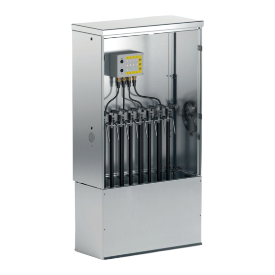
- Page 13 Figure 5. Hydrox Control Unit (HCU) Basic www.vexve.com...
- Page 14 www.vexve.com...
- Page 15 www.vexve.com...
- Page 16 Vexve Oy Pajakatu 11 Riihenkalliontie 10 FI-38200 Sastamala FI-23800 Laitila Finland Finland Tel. +358 10 734 0800 vexve.customer@vexve.com www.vexve.com www.vexve.com...
Need help?
Do you have a question about the Hydrox HCU Basic and is the answer not in the manual?
Questions and answers