Table of Contents
Advertisement
READ AND SAVE THESE INSTRUCTIONS
QUICK ASSEMBLY NOTES:
* Do not wire in fan while house wires are Live. Turn power off at breaker before installation
begins.
* Do not use any controls, wall or remote, other than those provided by Matthews Fan Company.
* Please do not use any electric or battery powered tools in the assembly and installation of this
or any other Matthews Fan Company product.
* Fan should be assembled and mounted by two people.
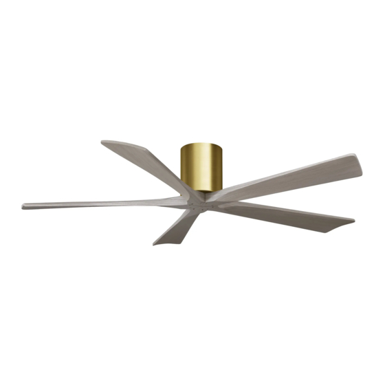
Irene-H
60", 52" or 42" CEILING FAN
Irene-5H
Irene-3H
FAN RATING AC 120V. 60Hz
For Damp Location
Advertisement
Table of Contents

Related Manuals for Atlas fan company Irene-H Series


Summary of Contents for Atlas fan company Irene-H Series
- Page 1 Irene-H 60", 52" or 42" CEILING FAN READ AND SAVE THESE INSTRUCTIONS Irene-3H Irene-5H FAN RATING AC 120V. 60Hz For Damp Location QUICK ASSEMBLY NOTES: * Do not wire in fan while house wires are Live. Turn power off at breaker before installation begins.
-
Page 2: Table Of Contents
TABLE OF CONTENTS Tools and Materials Required..................Package Contents ......................Safety Rules........................Mounting Options......................Hanging the Fan ......................Make the Electric Connections..................Finishing the Installation....................Attaching the Fan Blades....................Programming Your Fan and Operating the Remote Control and Wall Control....Operating Your Fan ..................... -
Page 3: Tools And Materials Required
1. TOOLS AND MATERIALS REQUIRED Philips screwdriver Blade screwdriver 11 mm wrench Step ladder Wire cutters 2. PACKAGE CONTENTS Unpack your fan and check the contents. You should have the following items: a-1. Blade set (3) (for Irene-3H) a-2. Blade set (5) (for Irene-5H) Mounting bracket (preassembled with fan motor assembly) Fan motor assembly... -
Page 4: Safety Rules
3. SAFETY RULES 1. To reduce the risk of electric shock, insure 8. To avoid personal injury or damage to the fan electricity has been turned off at the circuit and other items, be cautious when working breaker or fuse box before beginning. around or cleaning the fan. -
Page 5: Mounting Options
4. MOUNTING OPTIONS If there isn't an existing UL listed mounting box, then read the following instructions. Disconnect the power by removing fuses or turning off circuit breakers. Secure the outlet box directly to the building Outlet box structure. Use appropriate fasteners and building materials. -
Page 6: Hanging The Fan
5. HANGING THE FAN Outlet box REMEMBER to turn off the power. Follow the steps below to hang your fan properly: Step 1. Disassemble the mounting bracket from the fan motor assembly. Washers Mounting bracket Step 2. Attach the mounting bracket to the outlet Screws box using the two screws and washers provided with the outlet box. -
Page 7: Make The Electric Connections
6. MAKE THE ELECTRIC CONNECTIONS NOTE: Your fan has included as standard Outlet box equipment two types of controls: a hand held remote control and a wall mounted wall control. White ("AC IN N") You may use both as long as the dip switches Green or bare are calibrated the same. - Page 8 B. Wall mount remote control SUPPLY CIRCUIT a. Fan wire connection Ground 1. Connect the fan supply (black) wire to the black Conductor household supply wire. (Fig. 7) 2. Connect the neutral fan (white) wire to the white Ceiling neutral household wire. Outlet Box 3.
-
Page 9: Finishing The Installation
7. FINISHING THE INSTALLATION Step 1. Move fan motor into position over the Safety cable four mounting holes and secure with the four screws provided. (Fig. 9) Step 2. An additional safety support is provided Motor to prevent the fan from falling. Secure the safety cable to the ceiling joist with screw and washer. -
Page 10: Attaching The Fan Blades
8. ATTACHING THE FAN BLADES 1. Fasten blade to motor using the screws supplied. (Fig. 11) 2. Repeat process with other blades. Tighten each screw and make sure the blade is straight. NOTE: This fan is supplied with two types of Blade blades for installation. -
Page 11: Programming Your Fan And Operating The Remote Control And Wall Control
9. PROGRAMMING YOUR FAN AND OPERATING THE REMOTE CONTROL AND WALL CONTROL Before programming takes place, fan must be fully assembled and mounted to the ceiling with blades attached. You must also choose which control you will be using for programming the fan, the remote or the wall control. -
Page 12: Operating Your Fan
NOTE: If the self calibration test failed, turn the AC power off; restore power and process the self calibration test again. NOTE: During self calibration test, the remote and the wall control are non-functional. NOTE: The learning frequency function and self calibration test will continue to retain the last set frequency and calibration set even when the AC power is shut off. -
Page 13: Care Of Your Fan
11. CARE OF YOUR FAN Here are some suggestions to help you maintain your fan 1. Because of the fan's natural movement, some connections may become loose. Check the support connections, brackets, and blade attachments twice a year. Make sure they are secure. (It is not necessary to remove fan from ceiling.) 2. - Page 14 INSTRUCTIONS ON HOW TO PROGRAM MULTIPLE FANS ON SINGLE CIRCUIT BREAKER. 1. Turn the power off at the breaker/service box. 2. Hang all fans by convenience cable located in top of motor to hook in ceiling bracket. This will allow you to easily access the leads from house and the leads of the fan.
- Page 15 LIMITED LIFETIME WARRANTY MATTHEWS-GERBAR, LTD. DBA MATTHEWS FAN COMPANY LIFETIME LIMITED WARRANTY. warranted by Matthews-Gerbar, Ltd. to the original user against defects in workmanship or materials under normal use and inside or outside damp location installation for: Motors: Lifetime of original purchaser: Labor &...
Need help?
Do you have a question about the Irene-H Series and is the answer not in the manual?
Questions and answers