Table of Contents
Advertisement
Quick Links
READ AND SAVE THESE INSTRUCTIONS
QUICK ASSEMBLY NOTES:
* Do not wire in fan while house wires are Live, turn power off at breaker before installation
begins.
* Do not use any controls, wall or remote, other than what we provided.
* Please do not use any electric or battery powered tools in the assembly and installation of this
or any Matthews Fan Company product.
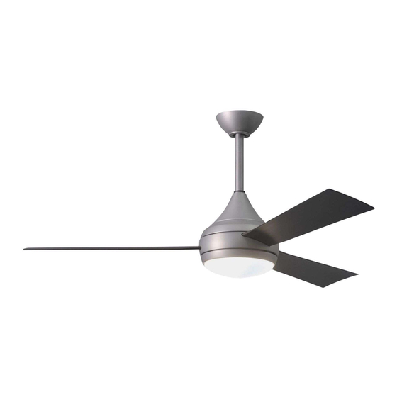
Donaire
52" CEILING FAN
AUSTRALIA ONLY
Model: YG480-DA (Donaire)
FAN RATING 220-240V, 50-60Hz,
69W (Fan: 51W, Light: 18W)
Net Weight: 9.5Kg
Advertisement
Table of Contents

Related Manuals for Atlas fan company Donaire YG480-DA


Summary of Contents for Atlas fan company Donaire YG480-DA
- Page 1 Donaire 52” CEILING FAN READ AND SAVE THESE INSTRUCTIONS Model: YG480-DA (Donaire) FAN RATING 220-240V, 50-60Hz, 69W (Fan: 51W, Light: 18W) Net Weight: 9.5Kg QUICK ASSEMBLY NOTES: * Do not wire in fan while house wires are Live, turn power off at breaker before installation begins.
-
Page 2: Table Of Contents
TABLE OF CONTENTS Tools and Materials Required..................Package Contents ......................Safety Rules........................Mounting Options......................Attaching the Fan Blades....................Hanging the Fan ......................Make the Electric Connections..................Finishing the Installation....................Attaching the Fan Blades....................Installing the Light Kit..................... Operating the Remote Control..................Operating Your Fan ..................... -
Page 3: Tools And Materials Required
1. TOOLS AND MATERIALS REQUIRED Philips screwdriver Blade screwdriver 11 mm wrench Step ladder Wire cutters 2. PACKAGE CONTENTS Unpack your fan and check the contents. You should have the following items: Blade set (3) Blade support plates (3) Hanger bracket Canopy Canopy bottom cover Downrod rubber cover... -
Page 4: Safety Rules
READ AND SAVE THESE SAFETY AND INSTALLATION INSTRUCTIONS. Consult a licensed electrician if unsure of any point below mentioned. DANGER/WARNING/CAUTION 1. High voltage and moving parts around motors and motor driven equipment can cause serious or fatal injuries. Always disconnect power source at main switch before wiring, servicing or cleaning unit. -
Page 5: Mounting Options
13. WARNING: This product is designed to use only those parts supplied with this product and/or accessories designated specifically for use with this product. Using parts and/or accessories not designated for use with this product could result in personal injury or property damage. 14. -
Page 6: Attaching The Fan Blades
5. HANGING THE FAN Ceiling hanger Before touching a screw driver thoroughly read bracket these instructions. Ceiling Warning/Caution: Before installing fan, turn off canopy power at service panel and check all visible screws and bolts for tightness. Canopy cover 1. Remove the decorative canopy bottom cover Figure 1 from the canopy by turning the cover counter clockwise. -
Page 7: Make The Electric Connections
9. Now lift the motor assembly into position and place the hanger ball into the hanger bracket. Rotate down rod until the "Check Tab" has dropped into the "Registration Slot" and the Screw down rod and ball assembly seat firmly. The down rod and ball assembly should not rotate if this is done correctly. - Page 8 5. Be sure to connect the male plug (from receiver) and female plug (from terminal block) Black (”LI” to fan) together. (Fig. 10 &11) Blue (LI) Brown (”L” to fan) Receiver 6. Be sure to snap together the male and Blue Black (L) female plugs.
-
Page 9: Finishing The Installation
7. FINISHING THE INSTALLATION Hanger 1. Slide the canopy up to hanger bracket and bracket place the key hole on the canopy over the Screws screw on the hanger bracket, turn canopy until it locks in place at the narrow section of the key holes. -
Page 10: Installing The Light Kit
9. ATTACHING THE MOUNTING PLATE Step 1. Remove the 1 of 3 screws from the mounting ring and keep it for future use. Loosen the other 2 screws. (Do not remove) Step 2. Place the key holes on the mounting plate over the 2 screws previously loosened from the mounting ring, turn mounting plate until it locks in place at the narrow section of the key holes. -
Page 11: Operating The Remote Control
11. OPERATING THE Light dimmer function REMOTE CONTROL select switch LEARN MODE PROCESS 1. Control and receiver have been factory ON/OFF programmed. If replacing the transmitter or DIMMER receiver, the learn mode process will need to be Learning used. (Fig. 16) button 2. -
Page 12: Operating Your Fan
12. OPERATING YOUR Speed settings for warm or cool weather depend on factors such as the room size. Ceiling height, number of fans and so on. NOTE: To operate the reverse function on this fan, press the reverse button while the fan is running. -
Page 13: Care Of Your Fan
13. CARE OF YOUR FAN Here are some suggestions to help you maintain your fan 1. Because of the fan's natural movement, some connections may become loose. Check the support connections, brackets, and blade attachments twice a year. Make sure they are secure. (It is not necessary to remove fan from ceiling.) 2. - Page 14 MOTOR: The Atlas Fan Company (Atlas) warrants to the original consumer purchaser of each Atlas Fan ("You"), that if any part of the motor, excluding the wall controls, remote controls or pull cord mechanisms ("Controls”) fails due to a defect in material or workmanship ("Defect") during your lifetime while the Atlas Fan is still installed in the exact...
- Page 15 IN-HOME (ON-SITE) WARRANTY? The Atlas 12 month in-home warranty covers Atlas ceiling fans installed within the coverage of our network of service agents in cases where the product fails due to defective materials or workmanship. This warranty does not cover installation faults, house wiring faults, loose blades or fittings or damage of any kind. Claims regarding corrosion damage are subject to case by case appraisal.
- Page 16 Note: Signals sent through the power grid by the electricity supplier for the control of off peak hot water, street lights and other devices may cause an intermittent humming noise in your electrical appliances such as your ceiling fan. Filters are available in Australia at the customer's expense. These noises do not occur as a result of a faulty fan.
Need help?
Do you have a question about the Donaire YG480-DA and is the answer not in the manual?
Questions and answers