Table of Contents
Advertisement
Quick Links
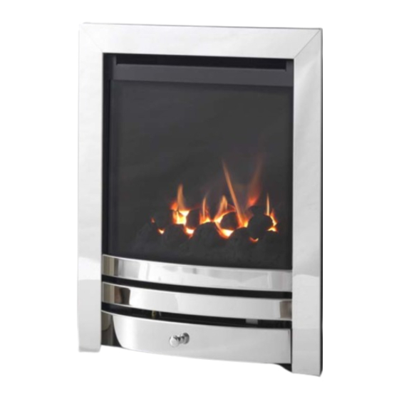
PESARO HE GAS FIRE
USER INSTRUCTIONS
INSTALLATION INSTRUCTIONS
SERVICE INSTRUCTIONS
It is a regulaon that these instrucons be handed to the customer aer installaon is complete. It is
also the responsibility of the installaon engineer to ensure that the customer is able to fully operate
the appliance and is aware of any cleaning or maintenance requirements.
Model numbers: F-0410X1 MANUAL for use on Natural Gas (G20) at a supply pressure of 20 mbar in GB / I.E.
Model numbers: F-0410X2 SLIDE for use on Natural Gas (G20) at a supply pressure of 20 mbar in GB / I.E.
(X denotes trim type)
This product is not suitable for primary heang purposes.
P-XX1530 ISSUE9
Advertisement
Table of Contents

Subscribe to Our Youtube Channel
Related Manuals for Wildfire PESARO HE


Summary of Contents for Wildfire PESARO HE
- Page 1 PESARO HE GAS FIRE USER INSTRUCTIONS INSTALLATION INSTRUCTIONS SERVICE INSTRUCTIONS It is a regulaon that these instrucons be handed to the customer aer installaon is complete. It is also the responsibility of the installaon engineer to ensure that the customer is able to fully operate the appliance and is aware of any cleaning or maintenance requirements.
-
Page 2: Table Of Contents
CONTENTS Regulatory Informaon and Installaon Requirements …………………………... 3 Installaon Requirements (connued) ………………………………………………….. 4 Sing the Appliance ……………………………………………………………………………… 5 Fixing the Appliance ...………………………………………………………………………...… 7 Front glass removal and replacement ……………………………………………………. 8 Connecng the Appliance to the Gas Supply ……………………………………….. 9 Checking Operaon of Appliance …………………………………………………………... -
Page 3: Regulatory InformaOn And InstallaOn Requirements
REGULATORY INFORMATION AND INSTALLATION REQUIREMENTS THE FOLLOWING MUST BE NOTED PRIOR TO THE INSTALLATION OF THIS APPLIANCE. This gas appliance MUST be installed by a GAS SAFE registered installer by law. It must be installed in accordance to these installaon instrucons and the GAS SAFETY (Installaon & Use) REGULATIONS 1998 as amended. Non compliance of this law may lead to prosecuon and it is in the interest of you and your family that this condion is observed. -
Page 4: InstallaOn Requirements (ConNued)
No purpose made venlaon is normally required for this appliance when installed in G.B. If the appliance is being installed in I.E then refer to I.S 813:1996 (Domesc Gas Installaon—Naonal Standards Authority of Ireland). Venlaon areas (if applicable) should be checked periodically to ensure there is no obstrucon, even though none is normally required for this appliance. -
Page 5: SiNg The Appliance
SITING THE APPLIANCE Fireplace Opening This fire is suitable for fing to non-combusble fireplace back panels with a temperature rang of at least 150 . (This is also known as CLASS”O” - If in doubt please contact the supplier of the back panel supplier to check suitability. - Page 6 Fireplace Opening (Hole in the Wall Installaon) This appliance MUST be installed in accordance with all relevant secons of document ‘J’ of the building regulaons. This appliance may be installed such that the base of the appliance sit on the surface of a fireplace opening at least 110mm up from the floor—this dimension ensures that there is no incandescent material (flame or ceramic impinged by flame) is less than 225mm from the floor.—This is a requirement of document ‘J’of the building regulaons.
-
Page 7: Fixing The Appliance
Fixing the Appliance. If the appliance is being installed with a spacer kit, this should be aached to the appliance using the screws included and the foam seal which is supplied with the appliance should be affixed to the rear face of the spacer. Do not use any ... -
Page 8: Front Glass Removal And Replacement
Removal of the front glass panel. The top glass clamp is held in place with 3 screws. This panel is concealed behind the top cover strip which is held in place by two magnets. The two magnets are fied to the top glass clamp as shown in this diagram. -
Page 9: ConnecNg The Appliance To The Gas Supply
Connecng the Appliance to the Gas Supply The gas supply can be connected to the appliance by a concealed fing from the rear. In all installaon condions the gas connecon should be provided using 8mm (O/D) copper tubing. If the concealed installaon method is chosen, there are ... -
Page 10: CompleNg The InstallaOn
Compleng the Installaon of the Appliance Remove the protecve covering (if applicable) from the face of the decorave trim. Fit the trim to the appliance with the magnets provided. One magnet should be placed in each corner of the trim at the top of the appliance and on each side about 120mm from the base of the appliance. -
Page 11: Appliance Technical InformaOn
Maintenance of the Appliance The following procedures can and should be performed by the customer at regular intervals depending upon use of the appliance. Appliance Technical Informaon Gas Type : Natural Gas Category : I2H Inlet Pressure: (Cold) 20mbar Heat Input Gross : 3.7kW Injector : 280 Desnaon Countries : GB/ IE... -
Page 12: Service InstrucOns
Cleaning the Appliance (connued) Trim, Fret and Painted Metal Parts There are a variety of trim and fret opons which may have been supplied with your appliance and these are normally a plated material on a steel substrate. It is important that no abrasive cleaners or chemical agents are used in the cleaning of these components. - Page 13 Removal / Replacement of Gas Carrying Components (connued) Manual Control Valve Remove the control knob from the valve. Remove the locknut from the front of the valve. Undo the three nuts around the periphery of the valve body—Gas Inlet / Burner / Pilot Remove the thermocouple nut from the back of the valve.
-
Page 14: User InstrucOns
OPERATING INSTRUCTIONS This appliance is available with two operang methods, namely manual control and slide control. The following instrucons detail both methods of operaon however the basic operaon of the appliance involves the ignion of a pilot burner (See page 7 for spillage monitoring details—ODS), then the control of the main burner with LOW and HIGH sengs. -
Page 15: Coal Layout InstrucOns
FUEL BED LAYOUT (COAL) The following instrucons detail how the ceramic fuel bed and loose components are to be installed onto the appliance. Great care should be taken when handling these ceramic parts as they are fragile and can easily be broken. Do not force any component into posion, if it does not fit easily then you are not fing the part correctly. - Page 16 Step 3 Fit the right hand ceramic component onto the fuel bed as shown in the picture below. ...
-
Page 17: Product Fiche
Product Fiche Manufacturer : Hearth Products Ltd Model No. F-041XX2 Fuel Type Natural Gas I2H Energy Efficiency Class Indirect Heang Funconality Direct Heat Output kW 2.7kW Indirect Heat Output kW Useful Energy Efficiency (NCV) High : 82.0% Useful Energy Efficiency (NCV) Nominal Heat Output High : 2.7kW Nominal Heat Output... -
Page 18: Spare Parts List
User Replaceable Parts Part Number Descripon P-XX11501 Ceramic Fuel Bed-Coal and modular coals (Complete) P-XX1380A Glass Panel (Silk Screened) To order spare parts for your appliance visit www.hearthproducts.co.uk/sparesshop or call us directly on 01785 225401 It is important to note that the above spares are user serviceable components that can be changed by the customer. The spares shop also features other components which may have to be installed by a Gas Safe engineer.
Need help?
Do you have a question about the PESARO HE and is the answer not in the manual?
Questions and answers