Table of Contents
Advertisement
Quick Links
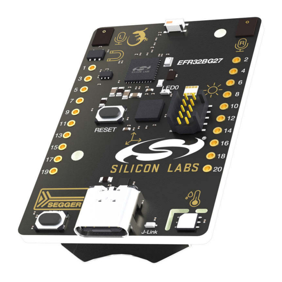
UG554: xG27 Dev Kit User's Guide
The xG27 Dev Kit is a low-cost, small form factor prototype and
development platform for the EFR32BG27 Wireless Gecko Sys-
tem-on-Chip.
The board is a small and cost-effective, feature-rich, prototype and development platform
based on the EFR32™ Wireless Gecko System-on-Chip. The xG27 Dev Kit is an ideal
platform for developing energy-friendly connected IoT devices.
The xG27 Dev Kit ships with a Bluetooth demo that works with a cloud connected smart-
phone app, showcasing easy collection of environmental and motion sensor data, as well
as button and LED control.
A built in SEGGER J-Link debugger ensures easy debugging through the USB Micro-B
connector.
silabs.com | Building a more connected world.
Copyright © 2023 by Silicon Laboratories
TARGET DEVICE
• EFR32 Wireless Gecko System-on-Chip
(EFR32BG27C140F768IM40)
• Cortex-M33 w/FPU with 76.8 MHz
maximum operating frequency
• 512 kB flash and 32 kB RAM
• Energy-efficient radio core with low
active and sleep currents
• Bluetooth 5.2 Direction Finding
• Integrated PA with up to 8 dBm
(2.4 GHz) TX power
• Secure Boot with Root of Trust and
Secure Loader (RTSL)
KIT FEATURES
• 2.4 GHz ceramic chip antenna
• Power control of on-board peripherals for
ultra-low-power operation
• Relative humidity and temperature sensor
• Ambient light sensor
• Hall effect sensor
• 6-axis inertial sensor
• PDM stereo microphones
• 8 Mbit flash for OTA programming and
data logging
• User LED and push button
• 20-pin 2.54 mm breakout pads
• SEGGER J-Link on-board debugger
• Virtual COM port
• Packet Trace Interface (PTI)
• Mini Simplicity connector for AEM and
packet trace using external Silicon Labs
debugger
• USB or coin cell battery powered.
SOFTWARE SUPPORT
• Simplicity Studio™
Rev. 1.0
Advertisement
Table of Contents

Related Manuals for Silicon Laboratories xG27


Summary of Contents for Silicon Laboratories xG27
- Page 1 • 512 kB flash and 32 kB RAM • Energy-efficient radio core with low The xG27 Dev Kit ships with a Bluetooth demo that works with a cloud connected smart- active and sleep currents phone app, showcasing easy collection of environmental and motion sensor data, as well •...
-
Page 2: Table Of Contents
Table of Contents 1. Introduction ....... . 4 1.1 Kit Contents ....... 4 1.2 Getting Started . - Page 3 5.2.3 Applied Emission Limits ......24 5.3 Relaxation with Modulated Carrier ..... . .24 5.4 Radiated Power Measurements .
-
Page 4: Introduction
Programming the xG27 Dev Kit is easily done using a USB Micro-B cable and the on-board J-Link debugger. A USB virtual COM port provides a serial connection to the target application, and the Packet Trace Interface (PTI) offers invaluable debug information about transmitted and received packets in wireless links. -
Page 5: Kit Hardware Layout
UG554: xG27 Dev Kit User's Guide Introduction 1.4 Kit Hardware Layout xG27 Dev Kit layout is shown below. 2.4 GHz Chip Antenna EFR32BG27 Left PDM Right PDM 30.4 mm Wireless Gecko Microphone Microphone Top View Bottom View Hall Effect Sensor... -
Page 6: Specifications
UG554: xG27 Dev Kit User's Guide Specifications 2. Specifications 2.1 Recommended Operating Conditions The following table provides guidelines for correct use of the xG27 Dev Kit, indicating typical operating conditions and some design limits. Table 2.1. Recommended Operating Conditions Parameter... -
Page 7: Current Consumption
In many cases the given conditions differ from the operating conditions on the xG27 Dev Kit, but the table can still be used as an indication of how much each feature contributes to the total current consumption. - Page 8 UG554: xG27 Dev Kit User's Guide Specifications Parameter Symbol Condition Unit On-board Debugger Sleep On-board debugger current consumption when USB cable is not inserted (EFM32GG12 EM4S mode current con- Current Consumption sumption) Minimum Board Current Minimum total board current consumption for VMCU = 3.0 µA...
-
Page 9: Hardware
UG554: xG27 Dev Kit User's Guide Hardware 3. Hardware The core of the xG27 Dev Kit is the EFR32BG27 Wireless Gecko System-on-Chip. The board also contains several peripherals con- nected to the EFR32BG27. Refer to section 1.4 Kit Hardware Layout for hardware component placement and layout information. -
Page 10: Power Supply
VMCU net. It is important to follow this process to avoid power conflicts and backfeeding the battery. Powering the xG27 Dev Kit through the Mini Simplicity connector allows current measurements using the Advanced Energy Monitoring (AEM) as described in section 4.2 External... -
Page 11: Peripherals
3.4 Peripherals The xG27 Dev Kit contains a set of peripherals that can be accessed from the EFR32BG27. All the peripherals have enable signals which can be used to completely turn off the peripherals that are not in use, or they can be put into a state that draws a minuscule amount of power. -
Page 12: Si7021 Relative Humidity And Temperature Sensor
On the xG27 Dev Kit, the Si7021 is connected through a switch. The switch must therefore be enabled by setting EFR32_SENSOR_EN high before it can be used by the application. This enables power to the Si7021 and connects the I... -
Page 13: Veml6035 Ambient Light Sensor
C digital interface. On the xG27 Dev Kit, the VEML6035 is connected through a switch. The switch must therefore be enabled by setting EFR32_SEN- SOR_EN high before it can be used by the application. This enables power to the VEML6035 and connects the I... -
Page 14: Icm-20648 6-Axis Inertial Sensor
X-, Y- and Z-axes with integrated 16-bit ADCs and programmable digital filters. On the xG27 Dev Kit, the ICM-20648 is connected through a switch. The switch must be enabled by setting EFR32_IMU_EN high before it can be used by the application. -
Page 15: Push Button And Led
The EFR32BG27 allows the PA04 pin, which is connected to TDI on the JTAG Debug Port, to be used for other purposes if JTAG is not used. The xG27 Dev Kit uses SWD as debugging interface and the PA04 pin of the EFR32BG27 is used to control LED0. Under certain circumstances, such as an unexpected reset during a debug session, control of the PA04 pin can be transferred to the debug port which will result in the user application losing control of the PA04 pin. -
Page 16: On-Board Debugger
3.5 On-board Debugger The xG27 Dev Kit contains a microcontroller separate from the EFR32BG27 Wireless Gecko that provides the user with an on-board J- Link debugger through the USB Type-C port. This microcontroller is referred to as the "on-board debugger" and is not programmable by the user. -
Page 17: Connectors
3.6 Connectors The xG27 Dev Kit features a Mini Simplicity Connector, a USB Type-C connector, and 20 breakout pads that follow the EXP header pinout. The connectors are placed on the top side of the board, and their placement and pinout are shown in the figure below. For additional information on the connectors, see the following sub-chapters. -
Page 18: Breakout Pads
The pin-routing on EFR32 is very flexible, so most peripherals can be routed to any pin. However, pins may be shared between the breakout pads and other functions on the xG27 Dev Kit. The table below includes an overview of the EXP header and functionality that is shared with the kit. -
Page 19: Mini Simplicity Connector
UG554: xG27 Dev Kit User's Guide Hardware 3.6.2 Mini Simplicity Connector The Mini Simplicity connector is a 10-pin, 1.27 mm pitch connector that allows the use of an external debugger such as the one found on a Silicon Labs Wireless Starter Kit mainboard. See section 4.2 External Debugger... -
Page 20: Debugging
4.2 External Debugger. When using an external debugger it is very important to make sure that there is no power source present on the xG27 Dev Kit, as the external debugger might source a voltage on the target power domain (VMCU). -
Page 21: On-Board Debugger
Wireless mainboard. It is possible to have the xG27 Dev Kit powered by a battery and still use the Mini Simplicity Connector with a Wireless mainboard for debugging and communication. In this case, the power switch on the Wireless mainboard must be set to the "BAT" position and the coin cell battery on the Wireless mainboard must be removed. -
Page 22: Radio
UG554: xG27 Dev Kit User's Guide Radio 5. Radio 5.1 RF Section This section gives a short introduction to the RF section of the BRD2602A board. The schematic of the RF section is shown in the figure below. 2.4 GHz... -
Page 23: Antenna
UG554: xG27 Dev Kit User's Guide Radio 5.1.4 Antenna The BRD2602A has an on-board ceramic antenna. The land pattern for the antenna on the PCB layout was designed based on the recommendations of the antenna data sheet. Because there is a significant difference between the layout (practically the board size) of the BRD2602A and the antenna evaluation board, the applied antenna matching network deviates from the recommendation. -
Page 24: Emc Regulations For 2.4 Ghz
UG554: xG27 Dev Kit User's Guide Radio 5.2 EMC Regulations for 2.4 GHz 5.2.1 ETSI EN 300-328 Emission Limits for the 2400-2483.5 MHz Band Based on ETSI EN 300-328, the allowed maximum fundamental power for the 2400-2483.5 MHz band is 20 dBm EIRP. For the unwan- ted emissions in the 1 GHz to 12.75 GHz domain the specified limit is -30 dBm EIRP. -
Page 25: Radiated Power Measurements
UG554: xG27 Dev Kit User's Guide Radio As it can be observed, the BLE 125 Kb/s coded modulation scheme has the lowest relaxation factors. These values will be used as the worst-case relaxation factors for the radiated measurements. 5.4 Radiated Power Measurements The output power of the EFR32BG27 was set to 8 dBm. -
Page 26: Antenna Pattern Measurement
UG554: xG27 Dev Kit User's Guide Radio 5.4.2 Antenna Pattern Measurement The measured typical antenna patterns are shown in the figures below. Normalized Radiation Pattern [dB], XY cut 0° 315° 45° 270° 90° 225° 135° Horizontal 180° Vertical Figure 5.4. Antenna Pattern - XY silabs.com | Building a more connected world. - Page 27 UG554: xG27 Dev Kit User's Guide Radio Normalized Radiation Pattern [dB], XZ cut 0° 315° 45° 270° 90° 225° 135° Horizontal 180° Vertical Figure 5.5. Antenna Pattern - XZ silabs.com | Building a more connected world. Rev. 1.0 | 27...
-
Page 28: Emc Compliance Recommendations
UG554: xG27 Dev Kit User's Guide Radio Normalized Radiation Pattern [dB], YZ cut 0° 315° 45° 270° 90° 225° 135° Horizontal 180° Vertical Figure 5.6. Antenna Pattern - YZ 5.5 EMC Compliance Recommendations 5.5.1 Recommendations for 2.4 GHz ETSI EN 300-328 Compliance As shown in the previous chapter, with the EFR32BG27 output power set to 8 dBm, the radiated power of the BRD2602A fundamental complies with the 20 dBm limit of the ETSI EN 300-328. -
Page 29: Schematics, Assembly Drawings, And Bom
UG554: xG27 Dev Kit User's Guide Schematics, Assembly Drawings, and BOM 6. Schematics, Assembly Drawings, and BOM Schematics, assembly drawings, and bill of materials (BOM) are available through Simplicity Studio when the kit documentation pack- age has been installed. They are also available from the kit page on the Silicon Labs website: silabs.com. -
Page 30: Kit Revision History
UG554: xG27 Dev Kit User's Guide Kit Revision History 7. Kit Revision History The kit revision can be found printed on the box label of the kit, as outlined in the figure below. The kit revision history is summarized in the table below. -
Page 31: Board Revision History And Errata
UG554: xG27 Dev Kit User's Guide Board Revision History and Errata 8. Board Revision History and Errata 8.1 Revision History The board revision can be found laser printed on the board, and the board revision history is summarized in the following table. -
Page 32: Document Revision History
UG554: xG27 Dev Kit User's Guide Document Revision History 9. Document Revision History Revision 1.0 June 2023 • Initial document version. silabs.com | Building a more connected world. Rev. 1.0 | 32... - Page 33 Note: This content may contain offensive terminology that is now obsolete. Silicon Labs is replacing these terms with inclusive language wherever possible. For more information, visit www.silabs.com/about-us/inclusive-lexicon-project Trademark Information Silicon Laboratories Inc. , Silicon Laboratories , Silicon Labs , SiLabs...
Need help?
Do you have a question about the xG27 and is the answer not in the manual?
Questions and answers