Table of Contents
Advertisement
Quick Links
UG525: EFR32xG24 2.4 GHz 10 dBm
Wireless Pro Kit User's Guide
A Wireless Pro Kit with the BRD4186C Radio Board is an excel-
lent starting point to get familiar with the EFR32™ Wireless Gecko
Wireless System-on-Chip. It also provides all necessary tools for
developing a Silicon Labs wireless application.
BRD4186C is a plug-in board for the Wireless Starter Kit Mainboard (BRD4001A) and
the Wireless Pro Kit Mainboard (BRD4002A). It is a complete reference design for the
EFR32xG24 Wireless SoC, with matching network and a PCB antenna for 10 dBm out-
put power in the 2.4 GHz band.
The mainboards contain an on-board J-Link debugger with a Packet Trace Interface and
a Virtual COM port, enabling application development and debugging of the attached ra-
dio board as well as external hardware. The mainboards also contain sensors and pe-
ripherals for easy demonstration of some of the EFR32's many capabilities.
This document describes how to use the BRD4186C Radio Board together with a Wire-
less Starter Kit Mainboard or a Wireless Pro Kit Mainboard.
silabs.com | Building a more connected world.
Copyright © 2022 by Silicon Laboratories
BRD4186C RADIO BOARD FEATURES
• EFR32xG24 Wireless Gecko Wireless
SoC with 1536 kB Flash and 256 kB RAM
(EFR32MG24B210F1536IM48).
• Inverted-F PCB antenna (2.4 GHz band)
• 8 Mbit low-power serial flash for over-the-
air upgrades
MAINBOARD FEATURES
• Advanced Energy Monitor
• Packet Trace Interface
• Virtual COM port
• SEGGER J-Link on-board debugger
• External device debugging
• Ethernet and USB connectivity
• Silicon Labs Si7021 relative humidity and
temperature sensor
• Low-power 128x128 pixel Memory LCD-
TFT
• User LEDs / pushbuttons
• 20-pin 2.54 mm EXP header
• Breakout pads for Wireless SoC I/O
• CR2032 coin cell battery support
SOFTWARE SUPPORT
• Simplicity Studio™
• Energy Profiler
• Network Analyzer
ORDERING INFORMATION
• xG24-PK6009A
• xG24-RB4186C
Rev. 1.0
Advertisement
Table of Contents

Related Manuals for Silicon Laboratories Alcom UG525


Summary of Contents for Silicon Laboratories Alcom UG525
- Page 1 • Breakout pads for Wireless SoC I/O • CR2032 coin cell battery support SOFTWARE SUPPORT • Simplicity Studio™ • Energy Profiler • Network Analyzer ORDERING INFORMATION • xG24-PK6009A • xG24-RB4186C silabs.com | Building a more connected world. Copyright © 2022 by Silicon Laboratories Rev. 1.0...
-
Page 2: Table Of Contents
Table of Contents 1. Introduction ....... . 4 1.1 Radio Boards ......4 1.2 Mainboards . - Page 3 6.2.1 Connecting ......26 6.2.2 Built-in Help ......27 6.2.3 Command Examples .
-
Page 4: Introduction
UG525: EFR32xG24 2.4 GHz 10 dBm Wireless Pro Kit User's Guide Introduction 1. Introduction The EFR32xG24 Wireless Gecko Wireless SoC is featured on a radio board that plugs directly into a Wireless Starter Kit (Wireless STK) Mainboard or a Wireless Pro Kit Mainboard. The mainboards feature several tools for easy evaluation and development of wire- less applications. -
Page 5: Ordering Information
UG525: EFR32xG24 2.4 GHz 10 dBm Wireless Pro Kit User's Guide Introduction 1.3 Ordering Information BRD4186C can be obtained as part of the xG24-PK6009A EFR32xG24 +10 dBm Pro Kit or as a separate radio board, xG24-RB4186C. Table 1.1. Ordering Information Part Number Description Contents... -
Page 6: Hardware Overview
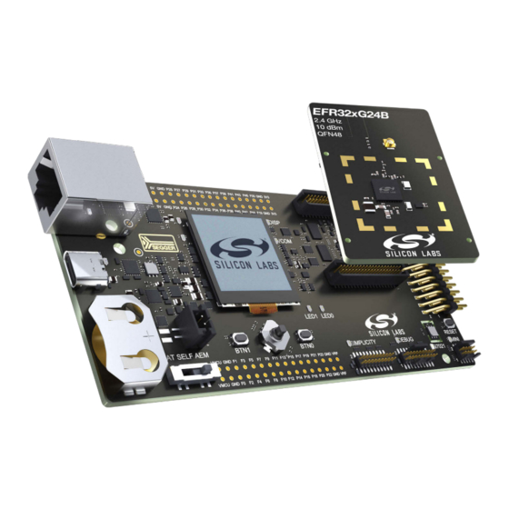
UG525: EFR32xG24 2.4 GHz 10 dBm Wireless Pro Kit User's Guide Hardware Overview 2. Hardware Overview 2.1 Hardware Layout The layout of the EFR32xG24 2.4 GHz 10 dBm Wireless Pro Kit when the radio board is combined with a Wireless Pro Kit Mainboard (BRD4002A) or a Wireless STK Mainboard (BRD4001A) is shown below. -
Page 7: Block Diagram
UG525: EFR32xG24 2.4 GHz 10 dBm Wireless Pro Kit User's Guide Hardware Overview 2.2 Block Diagram An overview of the EFR32xG24 2.4 GHz 10 dBm Wireless Pro Kit is shown in the figure below. RJ-45 Ethernet Board Connector Controller Connector Simplicity UART Multiplexer... -
Page 8: Connectors
UG525: EFR32xG24 2.4 GHz 10 dBm Wireless Pro Kit User's Guide Connectors 3. Connectors This chapter gives you an overview of the mainboard connectivity. The placement of the connectors on the Wireless Pro Kit Mainboard (BRD4002A) and the Wireless STK Mainboard (BRD4001A) is shown below. EXP Header P101 Mini Simplicty... -
Page 9: Breakout Pads
UG525: EFR32xG24 2.4 GHz 10 dBm Wireless Pro Kit User's Guide Connectors 3.3 Breakout Pads Most of the EFR32 pins are routed from the radio board to breakout pads at the top and bottom edges of the mainboard. A 2.54 mm pitch pin header can be soldered on for easy access to the pins. - Page 10 UG525: EFR32xG24 2.4 GHz 10 dBm Wireless Pro Kit User's Guide Connectors BOTTOM EDGE VMCU VMCU VCOM_CTS / EXP3 / PB05 / P0 P1 / PC01 / EXP4 / FLASH_MOSI / DISP_SI VCOM_RTS / EXP5 / PA00 / P2 P3 / PC02 / EXP6 / FLASH_MISO EXP7 / PA05 / P4 P5 / PC03 / EXP8 / FLASH_SCLK / DISP_SCLK EXP9 / PD02 / P6...
-
Page 11: Exp Header
UG525: EFR32xG24 2.4 GHz 10 dBm Wireless Pro Kit User's Guide Connectors 3.4 EXP Header The EXP header is an angled, 20-pin expansion header that allows connection of peripherals or plugin boards to the kit. It is located on the right-hand side of the mainboard and contains several I/O pins that can be used with most of the EFR32 Wireless Gecko's features. Additionally, the VMCU, 3V3, and 5V power rails are also exposed. -
Page 12: Exp Header Pinout
UG525: EFR32xG24 2.4 GHz 10 dBm Wireless Pro Kit User's Guide Connectors 3.4.1 EXP Header Pinout The pin-routing on the EFR32 is very flexible, so most peripherals can be routed to any pin. However, many pins are shared between the EXP header and other functions on the mainboard. The table below includes an overview of the mainboard features that share pins with the EXP header. -
Page 13: Debug Connector
UG525: EFR32xG24 2.4 GHz 10 dBm Wireless Pro Kit User's Guide Connectors 3.5 Debug Connector The debug connector serves multiple purposes based on the "debug mode" setting which can be configured in Simplicity Studio. When the debug mode is set to "Debug IN", the debug connector can be used to connect an external debugger to the EFR32 on the radio board. -
Page 14: Simplicity Connector
UG525: EFR32xG24 2.4 GHz 10 dBm Wireless Pro Kit User's Guide Connectors 3.6 Simplicity Connector The Simplicity Connector enables the advanced debugging features, such as the AEM, the virtual COM port, and the Packet Trace Interface, to be used towards an external target. The pinout is illustrated in the figure below. VMCU VCOM_TX VCOM_RX... -
Page 15: Mini Simplicity Connector
UG525: EFR32xG24 2.4 GHz 10 dBm Wireless Pro Kit User's Guide Connectors 3.7 Mini Simplicity Connector The Mini Simplicity Connector on the Wireless Pro Kit Mainboard offers advanced debugging features on a 10-pin connector to be used towards an external target. The Mini Simplicity Connector offers the following features: •... -
Page 16: Debug Adapter
UG525: EFR32xG24 2.4 GHz 10 dBm Wireless Pro Kit User's Guide Connectors 3.8 Debug Adapter The BRD8010A STK/WSTK Debug Adapter is an adapter board which plugs directly into the debug connector and the Simplicity Con- nector on the mainboard. It combines selected functionality from the two connectors to a smaller footprint 10-pin connector, which is more suitable for space-constrained designs. -
Page 17: Power Supply And Reset
UG525: EFR32xG24 2.4 GHz 10 dBm Wireless Pro Kit User's Guide Power Supply and Reset 4. Power Supply and Reset 4.1 Radio Board Power Selection The EFR32 on a Wireless Pro Kit can be powered by one of these sources: •... -
Page 18: Kit Power
UG525: EFR32xG24 2.4 GHz 10 dBm Wireless Pro Kit User's Guide Power Supply and Reset 4.2 Kit Power There are normally two main contributions to the power consumption from the mainboard USB connector, i.e., two main current paths: • One being monitored by the AEM that goes to the target power domain (VMCU) •... -
Page 19: Peripherals
UG525: EFR32xG24 2.4 GHz 10 dBm Wireless Pro Kit User's Guide Peripherals 5. Peripherals The Wireless Pro Kit has a set of peripherals that showcase some of the EFR32 features. Note that most EFR32 I/Os routed to peripherals are also routed to the breakout pads or the EXP header, which must be taken into consideration when using these I/Os. -
Page 20: Memory Lcd-Tft Display
UG525: EFR32xG24 2.4 GHz 10 dBm Wireless Pro Kit User's Guide Peripherals 5.2 Memory LCD-TFT Display A 1.28-inch SHARP Memory LCD-TFT is available on the kit to enable interactive applications to be developed. The display has a high resolution of 128 x 128 pixels and consumes very little power. It is a reflective monochrome display, so each pixel can only be light or dark, and no backlight is needed in normal daylight conditions. -
Page 21: Serial Flash
UG525: EFR32xG24 2.4 GHz 10 dBm Wireless Pro Kit User's Guide Peripherals 5.3 Serial Flash The BRD4186C Radio Board is equipped with an 8 Mbit Macronix MX25R SPI flash that is connected directly to the EFR32. The figure below shows how the serial flash is connected to the EFR32. VMCU PC03 (US1_CLK) SCLK... -
Page 22: Si7021 Relative Humidity And Temperature Sensor
UG525: EFR32xG24 2.4 GHz 10 dBm Wireless Pro Kit User's Guide Peripherals 5.4 Si7021 Relative Humidity and Temperature Sensor The Si7021 I C relative humidity and temperature sensor is a monolithic CMOS IC integrating humidity and temperature sensor ele- ments, an analog-to-digital converter, signal processing, calibration data, and an I C Interface. -
Page 23: Virtual Com Port
UG525: EFR32xG24 2.4 GHz 10 dBm Wireless Pro Kit User's Guide Peripherals 5.5 Virtual COM Port An asynchronous serial connection to the board controller is provided for application data transfer between a host PC and the target EFR32. This eliminates the need for an external serial port adapter. Isolation &... -
Page 24: Host Interfaces
UG525: EFR32xG24 2.4 GHz 10 dBm Wireless Pro Kit User's Guide Peripherals 5.5.1 Host Interfaces Data can be exchanged between the board controller and the target device through the VCOM interface, which is then available to the user in two different ways: •... -
Page 25: Hardware Handshake
UG525: EFR32xG24 2.4 GHz 10 dBm Wireless Pro Kit User's Guide Peripherals 5.5.3 Hardware Handshake The VCOM peripheral supports basic RTS/CTS flow control. VCOM_CTS (target clear to send) is a signal that is output from the board controller and input to the target device. The board controller de-asserts this pin whenever its input buffer is full and it is unable to accept more data from the target device. -
Page 26: Board Controller
UG525: EFR32xG24 2.4 GHz 10 dBm Wireless Pro Kit User's Guide Board Controller 6. Board Controller 6.1 Introduction The Wireless STK Mainboard and the Wireless Pro Kit Mainboard contain a dedicated microcontroller for some of the advanced kit features provided. This microcontroller is referred to as the board controller and is not programmable by the user. The board controller acts as an interface between the host PC and the target device on the radio board, as well as handling some housekeeping functions on the board. -
Page 27: Built-In Help
UG525: EFR32xG24 2.4 GHz 10 dBm Wireless Pro Kit User's Guide Board Controller 6.2.2 Built-in Help The admin console has a built-in help system which is accessed by the command. The command will print a list of all top help help level commands: WPK>... -
Page 28: Host To Target
UG525: EFR32xG24 2.4 GHz 10 dBm Wireless Pro Kit User's Guide Board Controller 6.3.2 Host to Target Host to target communication utilizes SEGGER's Real Time Transfer (RTT) technology. A full explanation of how this works can be found in J-Link/J-Trace User Guide (UM08001). Briefly summarized, RTT consists of a structure called the RTT Control Block, which is located in RAM. -
Page 29: Advanced Energy Monitor
UG525: EFR32xG24 2.4 GHz 10 dBm Wireless Pro Kit User's Guide Advanced Energy Monitor 7. Advanced Energy Monitor 7.1 Introduction Any embedded developer seeking to make their embedded code spend as little energy as the underlying architecture supports needs tools to easily and quickly discover inefficiencies in the running application. This is what the Simplicity Energy Profiler is designed to do. In real-time, the Energy Profiler will graph and log current as a function of time while correlating this to the actual target application code running on the EFR32. -
Page 30: Aem Details
UG525: EFR32xG24 2.4 GHz 10 dBm Wireless Pro Kit User's Guide Advanced Energy Monitor 7.3.1 AEM Details The main differences between the AEM on the Wireless Pro Kit Mainboard (BRD4002A) and the Wireless STK Mainboard (BRD4001A) is summarized in the table below with more in-depth information given in the text to follow. Table 7.1. -
Page 31: On-Board Debugger
UG525: EFR32xG24 2.4 GHz 10 dBm Wireless Pro Kit User's Guide On-Board Debugger 8. On-Board Debugger The Wireless Pro Kit Mainboard and the Wireless STK Mainboard contain an integrated debugger, which can be used to download code and debug the EFR32. In addition to programming a target on a plug-in radio board, the debugger can also be used to program and debug external Silicon Labs EFM32, EFM8, EZR32, and EFR32 devices connected through the debug connector. -
Page 32: Debug Modes
UG525: EFR32xG24 2.4 GHz 10 dBm Wireless Pro Kit User's Guide On-Board Debugger 8.2 Debug Modes The kit can be used in various debug modes as explained in this chapter. The on-board debugger can be used to debug the EFR32 on the radio board, or it can be used to debug a supported external target board using either the debug connector or the Mini Simplicity Connector. -
Page 33: Debugging During Battery Operation
UG525: EFR32xG24 2.4 GHz 10 dBm Wireless Pro Kit User's Guide On-Board Debugger Board Host Controller Computer RADIO BOARD External Debug Probe DEBUG HEADER Figure 8.3. Debug IN Note: For "Debug IN" to work, the kit board controller must be powered through the Debug USB connector. Debug MINI: The Wireless Pro Kit mainboard features a dedicated Mini Simplicity Connector on the board. -
Page 34: Kit Configuration And Upgrades
UG525: EFR32xG24 2.4 GHz 10 dBm Wireless Pro Kit User's Guide Kit Configuration and Upgrades 9. Kit Configuration and Upgrades The kit configuration dialog in Simplicity Studio allows you to change the J-Link adapter debug mode, upgrade its firmware, and change other configuration settings. -
Page 35: Schematics, Assembly Drawings, And Bom
UG525: EFR32xG24 2.4 GHz 10 dBm Wireless Pro Kit User's Guide Schematics, Assembly Drawings, and BOM 10. Schematics, Assembly Drawings, and BOM Schematics, assembly drawings, and bill of materials (BOM) are available through Simplicity Studio when the kit documentation pack- age has been installed. -
Page 36: Kit Revision History
UG525: EFR32xG24 2.4 GHz 10 dBm Wireless Pro Kit User's Guide Kit Revision History 11. Kit Revision History The kit revision can be found printed on the kit packaging label, as outlined in the figure below. The revision history given in this section may not list every kit revision. -
Page 37: Document Revision History
UG525: EFR32xG24 2.4 GHz 10 dBm Wireless Pro Kit User's Guide Document Revision History 12. Document Revision History Revision 1.0 March 2022 Initial document version. silabs.com | Building a more connected world. Rev. 1.0 | 37... - Page 38 Note: This content may contain offensive terminology that is now obsolete. Silicon Labs is replacing these terms with inclusive language wherever possible. For more information, visit www.silabs.com/about-us/inclusive-lexicon-project Trademark Information Silicon Laboratories Inc. , Silicon Laboratories , Silicon Labs , SiLabs...
Need help?
Do you have a question about the Alcom UG525 and is the answer not in the manual?
Questions and answers