Advertisement
Quick Links
U P M P - F 9 6 0 - E M I F
UDP C8051F960/Si1020 MCU C
E MIF
A R D W I T H
U
'
G
SER
S
U ID E
1. Introduction
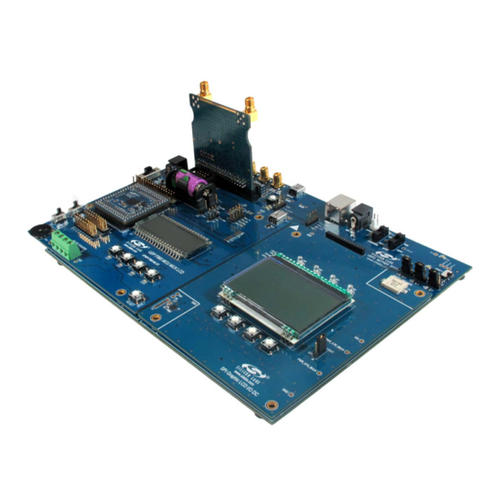
The Unified Development Platform (UDP) provides a development and demonstration platform for Silicon
Laboratories microcontrollers and the Silicon Laboratories software tools, including the Silicon Laboratories
Integrated Development Environment (IDE).
Figure 1. Unified Development Platform
Rev. 0.1 10/11
Copyright © 2011 by Silicon Laboratories
UPMP-F960-EMIF
Downloaded from
Elcodis.com
electronic components distributor
Advertisement

Related Manuals for Silicon Laboratories UDP C8051F960/Si1020


Summary of Contents for Silicon Laboratories UDP C8051F960/Si1020
- Page 1 U ID E 1. Introduction The Unified Development Platform (UDP) provides a development and demonstration platform for Silicon Laboratories microcontrollers and the Silicon Laboratories software tools, including the Silicon Laboratories Integrated Development Environment (IDE). Figure 1. Unified Development Platform Rev. 0.1 10/11 Copyright ©...
-
Page 2: Relevant Documents
UPMP-F960-EMIF 2. Relevant Documents This document provides a hardware overview for the Unified Development Platform (UDP) system UDP C8051F960/Si1020 MCU Card with EMIF. Additional information on the UDP system can be found in the documents listed in this section. 2.1. Motherboard User’s Guide The UDP Motherboard User’s Guide contains information on the motherboard features and can be found at www.silabs.com. -
Page 3: Hardware Setup
UPMP-F960-EMIF 3. Hardware Setup 3.1. Using the MCU Card Alone Refer to Figure 2 for a diagram of the hardware configuration when using the MCU card without a UDP motherboard. 1. Connect the USB Debug Adapter to the 2x5 debug connector on the MCU card with the 10-pin ribbon cable. - Page 4 UPMP-F960-EMIF 3.2. Using the MCU Card with the UDP Motherboard Refer to Figure 3 for a diagram of the hardware configuration when using the MCU card with a UDP motherboard. 1. Connect the MCU card to the UDP motherboard slot. 2.
- Page 5 UPMP-F960-EMIF USB Debug Adapter VBAT Switch Power Connector Adapter (J16) (J20) Figure 3. Hardware Setup using the Unified Development Platform 3.3. CP210x USB to UART VCP Driver Installation The MCU Card includes a Silicon Labs CP210x USB-to-Dual-UART Bridge Controller. Device drivers for the CP210x need to be installed before the PC software can communicate with the MCU through the UART interface.
- Page 6 MCU card can also be detached from the UDP and used alone as a development or demonstration tool. Figure 4 shows the UPMP-F960-EMIF MCU card. Figure 4. UPMP-F960-EMIF UDP MCU Card Figure 5 highlights some of the features of the UDP C8051F960/Si1020 MCU Card with EMIF. Rev. 0.1 Downloaded from Elcodis.com...
- Page 7 Potentiometer Pulse Counter Terminals Figure 5. UDP C8051F960/Si1020 MCU Card with EMIF 4.1. UPPI Pico Board Connector (J5, J6, J7, J8) The UPPI Pico Board connector accommodates a variety of C8051F96x and Si102x/3x UPPI Pico Boards. The C8051F960 MCU and Si1020 Wireless MCU UPPI Pico Boards share a common form factor. This enables the MCU card to support a wide variety of wired and wireless applications.
- Page 8 4.2. Push-Button Switches and LEDs (SW1–SW4, LED1–LED4) The UDP C8051F960/Si1020 MCU Card with EMIF has four push-button switches. The four switches connect to P3.0 through P3.3. The switches are normally open and pull the pin voltage to ground when pressed.
- Page 9 UPMP-F960-EMIF 4.6. Pin Power Supply Select Switches The C8051F960/Si1020 MCU has two VIO pins: VIO and VIORF. These VIO pins set the logic level and drive voltage for the MCU port pins. The VIORF pin sets the level for the port pins normally supporting radio functionality: P1.5 through P2.3.
- Page 10 UPMP-F960-EMIF 4.8. Potentiometer (R50) The potentiometer is available on P1.4. To facilitate a low-power potentiometer, P2.7 connects to bottom of the potentiometer as a potentiometer enable (POT_EN). Drive P2.7 low to enable the potentiometer. Alternatively, install a 0 resistor for R51 to continuously enable the potentiometer. 4.9.
- Page 11 UPMP-F960-EMIF 4.11. UPMP-F960-EMIF Board Default and Optional Connections The UPMP-F960-EMIF MCU card has many default and optional connections for use with different radios and the UDP motherboard. The default connections have shorting jumpers consisting of a 603 resistor footprint with a trace between the pads.
- Page 12 UPMP-F960-EMIF Table 1. MCU Pin Functions MCU Card Function UDP Motherboard Signal MCU Pin Default Optional Default Optional P3.2 SW3/LED3 P3.3 SW4/LED4 P3.4 RF_EBIF_NSS P4.6 ANT_A EZR_CLKIN/ EZRP2_GPIO3 P4.7 GPIO2 EZRP_RX_CLKOUT/ EZRP_GPIO2 4.11.1. P0.0 through P0.3 Pins P0.0 through P0.3 connect to the UDP SPI_LCD signals (SPI_LCD_SCK, SPI_LCD_MISO, SPI_LCD_MOSI, SPI_LCD_NSS) by default.
- Page 13 UPMP-F960-EMIF 4.11.11. EZRadio GPIO Signals When using a Si1020 UPPI Pico Board, the four EZRadioPRO GPIO signals connect to the SMA connectors on the motherboard. GPIO_0 connects to EZRP_TX_DATA_IN via R20. This signal supports direct mode TX input data from an external source using the SMA connector.
- Page 14 UPMP-F960-EMIF Table 2. MCU EMIF Connections (Continued) EMIF Configurations MCU Card Signal UDP Motherboard MCU Pin Non-Multiplexed Multiplexed Name Signal Name 16-bit 8-bit 16-bit 8-bit P6.3 EMIF_D3/AD3 EMIF_A3 P6.4 EMIF_D4/AD4 EMIF_A4 P6.5 EMIF_D5/AD5 EMIF_A5 P6.6 EMIF_D6/AD6 EMIF_A6 P6.7 EMIF_D7/AD7 EMIF_A7 Rev.
- Page 15 UPMP-F960-EMIF 5. Using the UPMP-F960-EMIF with the UDP Motherboard 5.1. VBAT Selector Switch When used with the UDP motherboard, the motherboard can power the UPMP-F960-EMIF MCU card. With the VBAT selector switch in the VREG position, the motherboard powers the regulator on the card. With the VBAT selector switch in the UDP position, the UDP motherboard powers VBAT directly.
- Page 16 Appendix. 5.4. Shorting Blocks: Factory Defaults The UDP C8051F960/Si1020 MCU Card with EMIF comes from the factory with pre-installed shorting blocks on several headers. Figure 7 shows the positions of the factory default shorting blocks. Figure 7. Shorting Blocks: Factory Defaults Shorting blocks are installed on P2 to connect P0.4 to MCU_TX and P0.5 to MCU_RX.
- Page 17 UPMP-F960-EMIF 6. Schematics Rev. 0.1 Downloaded from Elcodis.com electronic components distributor...
- Page 18 UPMP-F960-EMIF Rev. 0.1 Downloaded from Elcodis.com electronic components distributor...
- Page 19 UPMP-F960-EMIF Rev. 0.1 Downloaded from Elcodis.com electronic components distributor...
- Page 20 UPMP-F960-EMIF Rev. 0.1 Downloaded from Elcodis.com electronic components distributor...
- Page 21 UPMP-F960-EMIF Rev. 0.1 Downloaded from Elcodis.com electronic components distributor...
- Page 22 UPMP-F960-EMIF Rev. 0.1 Downloaded from Elcodis.com electronic components distributor...
-
Page 23: Bill Of Materials
UPMP-F960-EMIF 7. Bill of Materials Table 3. UDP C8051F960/Si1020 MCU Card with EMIF Bill of Materials Reference Part Number Source Description 24AA64T-I/MNY Microchip Technology 64KBIT I2C SERIAL FLASH, 400kHZ, 8- TDFN U4-5 SN74AVC4T245PWR Texas Instruments Quad Dual-Supply Level Shifter, TSSOP... - Page 24 UPMP-F960-EMIF Table 3. UDP C8051F960/Si1020 MCU Card with EMIF Bill of Materials (Continued) Reference Part Number Source Description DS5, LED1-4 SML-LX0603IW-TR Lumex LED, RED DIFF, 635NM, SMT0603, OR Opto/Components Inc EQ, RoHS LP2989AIMM-3.3/NOPB National LDO REG, 500MA, ADJ, MSOP, RoHS...
- Page 25 UPMP-F960-EMIF —MCU C PPENDIX EADER ESCRIPTIONS Table 4. UDP C8051F960/Si1020 MCU Card with EMIF H1 Pin Descriptions (J1) MCU Card Signal Name Usage USART_TX_A USART_RX_A USART_RTS_A USART_CTS_A USART_UCLK_A CAN_TX_B CAN_RX_B SPI_SCK_A Graphical LCD I/O Card SPI clock SPI_MISO_A Graphical LCD I/O Card SPI master-in, slave-out...
- Page 26 UPMP-F960-EMIF Table 4. UDP C8051F960/Si1020 MCU Card with EMIF H1 Pin Descriptions (J1) (Continued) MCU Card Signal Name Usage PCA_CH1_B I2SOUT_DFS_A I2SOUT_CLK_A I2SOUT_DOUT_A I2C_SDA_EZR EZRadioI2C data I2C_SCL_EZR EZRadio I2C clock TIMER_CT_A TIMER_EX_A TIMER_CT_B TIMER_EX_B UART_TX_A UART A transmit UART_RX_A UART A receive...
- Page 27 UPMP-F960-EMIF Table 4. UDP C8051F960/Si1020 MCU Card with EMIF H1 Pin Descriptions (J1) (Continued) MCU Card Signal Name Usage GPIO05 LED2/SW2 GPIO06 LED3/SW3 GPIO07 LED4/SW4 GPIO08 Graphical LCD I/O Card Backlight GPIO09 GPIO10 GPIO11 GPIO12 GPIO13 GPIO14 GPIO15 PORT_MATCH0 PORT_MATCH1...
- Page 28 UPMP-F960-EMIF Table 5. UDP C8051F960/Si1020 MCU Card with EMIF H2 Pin Descriptions (J2) MCU Card Signal Name Description UDPBUS_SDA_A Electronic Board ID I2C data UDPBUS_SCL_A Electronic Board ID I2C clock EPCA_ECI_MOTOR EPCA_CH0_MOTOR EPCA_CH1_MOTOR EPCA_CH2_MOTOR EPCA_CH3_MOTOR EPCA_CH4_MOTOR EPCA_CH5_MOTOR HVGPIO0 HVGPIO1 HVGPIO2...
- Page 29 UPMP-F960-EMIF Table 5. UDP C8051F960/Si1020 MCU Card with EMIF H2 Pin Descriptions (J2) MCU Card Signal Name Description EMIF_A4 EMIF D4/AD4 EMIF_A3 EMIF D3/AD3 EMIF_A2 EMIF D2/AD2 EMIF_A1 EMIF D1/AD1 EMIF_A0 EMIF D0/AD0 EMIF_WRB EMIF write signal (active low) EMIF_OEB...
- Page 30 UPMP-F960-EMIF Table 5. UDP C8051F960/Si1020 MCU Card with EMIF H2 Pin Descriptions (J2) MCU Card Signal Name Description LCD_SEG24_A LCD_SEG25_A LCD_SEG26_A LCD_SEG27_A LCD_SEG28_A LCD_SEG29_A LCD_SEG30_A LCD_SEG31_A LCD_SEG32_A LCD_SEG33_A LCD_SEG34_A LCD_SEG35_A LCD_SEG36_A LCD_SEG37_A LCD_SEG38_A LCD_SEG39_A LCD_COM0_A LCD_COM1_A LCD_COM2_A LCD_COM3_A LCD_COM4_A LCD_COM5_A...
- Page 31 UPMP-F960-EMIF Table 6. UDP C8051F960/Si1020 MCU Card with EMIF H3 Pin Descriptions (J3) MCU Card Description Description PWR_VDD_IN PWR_VDD_IN PWR_VDD_OUT Programmable Supply from UDP to VBAT (VBAT Select set to UDP) PWR_VDD_OUT PWR_RADIO_IN VDC Output of DCDC to power 40-pin radio card...
- Page 32 UPMP-F960-EMIF Table 6. UDP C8051F960/Si1020 MCU Card with EMIF H3 Pin Descriptions (J3) MCU Card Description Description EBID_NSS RF EBID SPI slave select C2_CLK_A Reset/C2 interface clock C2_DAT_A P7.0/C2 interface data C2_CLK_B C2_DAT_B C2_CLK_C C2_DAT_C C2_CLK_D C2_DAT_D C2_CLK_E C2_DAT_E JTAG_TDO_A...
- Page 33 UPMP-F960-EMIF Table 6. UDP C8051F960/Si1020 MCU Card with EMIF H3 Pin Descriptions (J3) MCU Card Description Description H3_75 H3_76 H3_77 H3_78 H3_79 H3_80 H3_81 H3_82 H3_83 H3_84 H3_85 H3_86 H3_87 H3_88 H3_89 H3_90 H3_91 H3_92 H3_93 H3_94 H3_95 H3_96 H3_97...
- Page 34 UPMP-F960-EMIF Table 7. UDP C8051F960/Si1020 MCU Card with EMIF H4 Pin Descriptions (J4) MCU Card Description Description C2D_TX00_A Capacitive Sensing output 0 C2D_TX01_A Capacitive Sensing output 1 C2D_TX02_A Capacitive Sensing output 2 C2D_TX03_A Capacitive Sensing output 3 C2D_TX04_A Capacitive Sensing output 4...
- Page 35 UPMP-F960-EMIF Table 7. UDP C8051F960/Si1020 MCU Card with EMIF H4 Pin Descriptions (J4) (Continued) MCU Card Description Description ADC_IN1 ADC_IN2 ADC_IN3 DAC_VREF DAC voltage reference DAC_VREFGND DAC voltage reference ground DAC_OUT0 DAC_OUT1 DAC_OUT2 DAC_OUT3 IDAC_A IDAC A output IDAC_B IDAC B output...
- Page 36 UPMP-F960-EMIF Table 7. UDP C8051F960/Si1020 MCU Card with EMIF H4 Pin Descriptions (J4) (Continued) MCU Card Description Description EZRP_SDN Radio card peripheral shutdown EZRP_NIRQ Radio card peripheral interrupt status EZR_NFFS EZR_SI100X_TX Radio card Si100x transmit EZR_DTO EZR_FFIT EZR_SI100X_RX Radio card Si100x receive...
- Page 37 UPMP-F960-EMIF OTES Rev. 0.1 Downloaded from Elcodis.com electronic components distributor...
-
Page 38: Contact Information
Silicon Laboratories products are not designed, intended, or authorized for use in applications intended to support or sustain life, or for any other application in which the failure of the Silicon Laboratories product could create a situation where per- sonal injury or death may occur.
Need help?
Do you have a question about the UDP C8051F960/Si1020 and is the answer not in the manual?
Questions and answers