Table of Contents
Advertisement
Quick Links
Advertisement
Chapters
Table of Contents

Related Manuals for turck BL67-GW-PN-AC


Summary of Contents for turck BL67-GW-PN-AC
- Page 1 USER MANUAL PROFINET AIDA-gateway BL67-GW-PN-AC...
- Page 2 No part of this manual may be reproduced in any form (printed, photocopy, microfilm or any other process) or processed, duplicated or distributed by means of electronic systems without written permission of Hans Turck GmbH & Co. KG, Muelheim an der Ruhr. Subject to alterations without notice...
-
Page 3: Table Of Contents
Communications in PROFINET ................................3-2 3.1.3 Address assignment ....................................3-3 3.1.4 Ethernet MAC-ID.....................................3-3 3.1.5 LLDP-Protokoll (Link Layer Discovery Protocol)..........................3-3 Technical features Function ................................4-2 Technical properties BL67-GW-PN-AC......................4-3 4.2.1 Gateway structure....................................4-4 4.2.2 Technical data......................................4-5 Connection possibilities..........................4-7 4.3.1 Fieldbus connection....................................4-7 4.3.2 Voltage supply via AIDA connector..............................4-7 4.3.3... - Page 4 4.9.1 Diagnostic messages via LEDs ................................4-10 4.10 Diagnosis in PROFINET ..........................4-13 4.10.1 Gateway Error codes ..................................4-13 4.10.2 Channel -specific error codes of the I/O-modules ........................4-14 4.11 Parameterization ............................4-17 4.11.1 Gateway parameters...................................4-17 4.11.2 Parameter "module parameterization"............................4-20 4.11.3 I/O-module-parameters ..................................4-21 4.12 Description of user data for acyclic services....................
- Page 5 Potential relationships............................7-4 7.2.1 General ........................................7-4 Electromagnetic compatibility (EMC) ......................7-5 7.3.1 Ensuring electromagnetic compatibility ............................7-5 7.3.2 Grounding of inactive metal components............................7-5 7.3.3 PE connection......................................7-5 7.3.4 Mounting rails......................................7-6 Shielding of cables ............................7-7 Potential compensation..........................7-8 7.5.1 Switching inductive loads ...................................7-8 7.5.2 Protection against Electrostatic Discharge (ESD) ........................7-8 Mounting and mounting instructions Mechanical mounting .............................8-2 8.1.1...
- Page 6 D301239 1013 - BL67 AIDA PROFINET...
-
Page 7: About This Manual
About this manual Documentation concept......................... 1-2 1.1.1 Additional documentation ................................1-2 Description of symbols used ......................1-3 General............................1-4 1.3.1 Prescribed use ....................................1-4 1.3.2 Notes concerning planning/ installation of this product ....................1-4 D301239 1013 - BL67 AIDA PROFINET... -
Page 8: Documentation Concept
In addition to that, the manual contains a short description of the I/O-ASSISTANT 3 (FDT/DTM), the project planning and configuration software tool for TURCK I/O-systems. D301239 1013 - BL67 AIDA PROFINET... -
Page 9: Description Of Symbols Used
Description of symbols used Description of symbols used Danger This sign can be found next to all notes that indicate a source of hazards. This can refer to danger to personnel or damage to the system (hardware and software) and to the facility. This sign means for the operator: work with extreme caution. -
Page 10: General
Please read this section carefully. Safety aspects cannot be left to chance when dealing with electrical equipment. This manual includes all information necessary for the prescribed use of TURCK BL67-devices. It has been specially conceived for personnel with the necessary qualifications. -
Page 11: Bl67 Philosophy
BL67 philosophy The basic concept........................... 2-2 2.1.1 Flexibility ......................................2-3 2.1.2 Easy to handle ....................................2-3 BL67 components........................... 2-4 2.2.1 Gateways ......................................2-4 2.2.2 Electronic modules ..................................2-5 – Power Feeding-modules ................................2-5 2.2.3 Base modules.....................................2-6 2.2.4 End plate......................................2-6 D301239 1013 - BL67 AIDA PROFINET... -
Page 12: The Basic Concept
BL67 philosophy The basic concept BL67 is a modular I/O system of protection class IP67 for use in industrial automation. It connects the sensors and actuators in the field with the higher-level master. BL67 offers modules for practically all applications: •... -
Page 13: Flexibility
The basic concept 2.1.1 Flexibility A BL67 station can contain modules in any combination, which means it is possible to adapt the system to practically all applications in automated industry. 2.1.2 Easy to handle All BL67 modules of the standard line, with the exception of the gateway, consist of a base module and an electronics module. -
Page 14: Bl67 Components
BL67 philosophy BL67 components Figure 2-1: BL67-station Agateway Belectronic module Cbase module 2.2.1 Gateways The gateway connects the fieldbus to the I/O modules. It is responsible for handling the entire process data and generates diagnostic information for the higher-level master and the software tool I/O- ASSISTANT 3 (FDT/DTM). -
Page 15: Electronic Modules
Note For detailed information about the individual BL67 I/O components, please refer to the chapters 2 to 8 of the manual "BL67- I/O-modules" (TURCK Documentation-No.: German German D300572; English D300529). The "Appendix" to the manual mentioned above contains (amongst others) a list of all BL67 components and the assignment of electronic modules to base modules. -
Page 16: Base Modules
BL67 philosophy 2.2.3 Base modules The field wiring is connected to the base modules. These are available in the following connection variations: 1 × M12, 2 × M12, 2 × M12-P, 4 × M12, 4 × M12-P 4 × M8, 8 × M8 ... -
Page 17: Profinet
PROFINET PROFINET ............................3-2 3.1.1 Distributed field devices with PROFINET..........................3-2 – Device Model....................................3-2 3.1.2 Communications in PROFINET ..............................3-2 – The PROFINET services ................................3-2 3.1.3 Address assignment..................................3-3 3.1.4 Ethernet MAC-ID....................................3-3 3.1.5 LLDP-Protokoll (Link Layer Discovery Protocol)........................3-3 D301239 1013 - BL67 AIDA PROFINET... -
Page 18: Distributed Field Devices With Profinet
PROFINET PROFINET PROFINET is the innovative open standard for the implementation of end-to-end integrated automation solutions based on Industrial Ethernet. With PROFINET , simple distributed I/O and time- critical applications can be integrated into Ethernet communication just as well as distributed automation system on an automation component basis. -
Page 19: Address Assignment
MAC address is determined for each device by the IEEE (Institute of Electrical and Electronics Engineers, New York). The first 3 bytes of the MAC address contain a manufacturer identifier (Turck: 00:07:46:xx:xx:xx). The last 3 bytes can be chosen freely by the manufacturer for each device and contain a definite serial number. - Page 20 PROFINET D301239 1013 - BL67 AIDA PROFINET...
-
Page 21: Technical Features
Technical features Function ............................4-2 Technical properties BL67-GW-PN-AC ................... 4-3 4.2.1 Gateway structure....................................4-4 4.2.2 Technical data ....................................4-5 Connection possibilities......................... 4-7 4.3.1 Fieldbus connection..................................4-7 4.3.2 Voltage supply via AIDA connector............................4-7 – System supply US1 ..................................4-7 – Field supply US2 ...................................4-7 4.3.3 Service interface (SVC - mini-USB connector)........................4-8... -
Page 22: Function
Technical features Function The gateway is used to connect BL67-IO modules to a PROFINET-network. The gateway handles the entire process data exchange between the I/O-level and the fieldbus and generates diagnostic information for higher-level nodes and the software tool I/O-ASSISTANT. The BL67 AIDA-gateways can be used either with the standard BL67 IO-modules or can be connected to valve terminals by means of special base elements. -
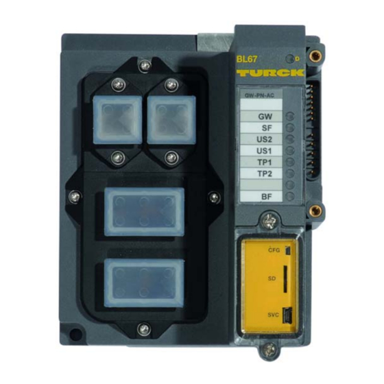
Page 23: Technical Properties Bl67-Gw-Pn-Ac
Technical properties BL67-GW-PN-AC Technical properties BL67-GW-PN-AC BL67 AIDA-gateway with two AIDA RJ45 (copper) connectors for the field bus connection. The connection of the supply voltage is done via two 5-pole AIDA power connectors. Figure 4-1: BL67-GW-PN-AC Voltage supply AIDA AIDA Ethernet... -
Page 24: Gateway Structure
Technical features 4.2.1 Gateway structure The BL67 gateway has the following structure: Figure 4-2: gateway BL67- structure System bus Memory Communi- cation bus Eth2 Eth1 Module bus- interface 5 VDC 1 2 3 4 5 24 VDC Power 1 2 3 4 5 Short circuit protection D301239 1013 - BL67 AIDA PROFINET... -
Page 25: Technical Data
Technical properties BL67-GW-PN-AC 4.2.2 Technical data Table 4-1: supply voltage Technical data Requirements for the power supply according to EN 61131-2 Ethernet gateway Double-tuned power supply of the BL67 system. System supply US1 24 V DC – for internal system supply on... - Page 26 Technical features Relative humidity 5 to 95 % (internal), level RH-2, no condensation (when stored properly) (stored at 45 °C), according to IEC 61131-2 Climatic tests according to IEC 61131-2 Corrosive gas according to IEC 60068-2-42/43 – SO 10 ppm (rel. humidity < 75 %, no condensation) –...
-
Page 27: Connection Possibilities
Connection possibilities Connection possibilities 4.3.1 Fieldbus connection The connection to Ethernet is realized via two AIDA Ethernet RJ45 (copper) connectors. Figure 4-3: 1 = YE (TX +) RJ45 connector 2 = OG (TX –) 3 = WH (RX +) 4 = n.c. 5 = n.c. -
Page 28: Service Interface (Svc - Mini-Usb Connector)
Technical features 4.3.3 Service interface (SVC - mini-USB connector) The service interface (SVC) is located under the gateway cover. The service interface is used to connect the gateway to the project planning and diagnostic software I/ O-ASSISTANT 3(FDT/DTM). The service interface is designed as a 5 pole mini-USB-connection. In order to connect the gateway’s service-interface to the PC, a commercial cable with mini USB connector (commonly used for e.g. -
Page 29: Set-Button (Cfg)
Namenszuweisung BL67-Gateway (page 5-14)). This can be done for example by using the HW-Config or the Primary Setup Tool from Siemens). GSDML-file The actual GSDML-file for the gateway can be downloaded from the TURCK-home page www.turck.com. D301239 1013 - BL67 AIDA PROFINET... -
Page 30: Status Indicators/Diagnostic Messages Gateway
Technical features Status indicators/diagnostic messages gateway Diagnostics messages are indicated in two different ways: via the LEDs via the respective configuration software 4.9.1 Diagnostic messages via LEDs Every BL67-gateway for PROFINET displays the following statuses via LEDs: LEDs for the module bus communication (module bus-LEDs): GW and IOs ... - Page 31 Status indicators/diagnostic messages gateway Table 4-3: Status Meaning Remedy LED-displays No power supply of the CPU. Check the system power supply at the gateway. green Firmware active, gateway ready green Firmware not active If LED “IOs“ red, then flashing, firmware-download 1 Hz necessary green...
- Page 32 Technical features Table 4-3: Status Meaning Remedy LED-displays Bus failure (no physical connection to a – Check the: subnet or switch). – connection to the switch – the data rate – the transmission type (full-duplex) IO device error – Check and eliminate the flashing possible causes: possible error-reasons...
-
Page 33: Diagnosis In Profinet
Diagnosis in PROFINET 4.10 Diagnosis in PROFINET In PROFINET, critical events (diagnostic messages) are reported acyclically as alarms. In addition to information as slot-number, subslot-number, channel type etc., the diagnostic telegrams contain error codes which define the diagnostic event more precisely. The error codes are interpreted by the PLC-software or respective function block, so that the diagnostic messages are normally displayed as plain text. -
Page 34: 4.10.2 Channel -Specific Error Codes Of The I/O-Modules
Technical features 4.10.2 Channel -specific error codes of the I/O-modules The channel-specific diagnostic messages of the I/O-modules using error codes are defined as follows: Table 4-5: Value (dec.) Diagnosis channel-specific error codes Error codes (1 to 9 according to the standards) Short circuit under voltage Overload... -
Page 35: Meaning Of The Error Codes For The Bl67 I/O-Modules
Diagnosis in PROFINET Meaning of the error codes for the BL67 I/O-modules The gateway changes the diagnostic messages sent by the BL67 I/O-modules to PROFINET error codes. The following table shows, which module message will be changed to which error code. Table 4-6: Error code Module diagnostics... - Page 36 Technical features Table 4-6: Error code Module diagnostics Error Codes / Text I/O module diagnostic message of the module module diagnos- (dec.) tics Underflow lower BL67-1CNT/ENC STS_UFLW (underflow) limit BL67-1SSI Sensor value underflow BL67-×AI-×/ Measurement value range error (OoR) BL67-×AO-× BL67-2AI2AO-V/I Error BL67-1CVI...
-
Page 37: Parameterization
Parameterization 4.11 Parameterization 4.11.1 Gateway parameters The BL67-gateways for PROFINET occupy 4 parameter bytes. Description of the gateway-parameters Table 4-7: Byte Bit parameters Value Meaning gateway parameters default Byte 0 setting bit 0, bit 1 Output behavior if one module is missing output 0 A The gateway switches the outputs of modules to "0". - Page 38 Technical features Table 4-7: Byte Bit parameters Value Meaning gateway parameters 0 bit 2, bit 3 Output behavior if one module is wrong default hold current value The gateway maintains the actual output settings of setting all modules (with the exception of analog output modules).
- Page 39 Parameterization Table 4-7: Byte Bit parameters Value Meaning gateway parameters Bit 2: Disable output power diagnosis default setting inactive A A monitoring of the field supply US2 (from the gateway and the Power-Feeding modules) is activated. If this parameter is set but the parameter "Diagnostics from modules"...
-
Page 40: 4.11.2 Parameter "Module Parameterization
Technical features 4.11.2 Parameter "module parameterization" Each parameterizable module, gets the additional parameter "module parameterization" via the GSDML-file of the gateway. Note This parameter is not part of the module parameters, but is only important for the communication between gateway and the modules. This parameter extension is always necessary, even if the module is parameterized via a IO- supervisor. -
Page 41: 4.11.3 I/O-Module-Parameters
Parameterization 4.11.3 I/O-module-parameters Digital input modules BL67-4DI-PD Table 4-8: Byte Parameter name Value Module parame- – Meaning ters 0 to 3 Input filter channel 0 = deactivate A 0 to 3 – input filter: 0.25 ms default setting 1 = activate: –... -
Page 42: Analog Input Modules
Technical features Analog input modules BL67-2AI-I (1 byte parameters per channel) Table 4-10: Byte Parameter name Value Module parame- – Meaning ters current mode 0 = 0...20 mA A default 1 = 4...20 mA setting Value representation 0 = Integer (15 bit + sign) A 1 = 12 bit (left-justified) Diagnosis 0 = activate A... - Page 43 Parameterization BL67-2AI-PT (2 byte parameters per channel) Table 4-12: Byte Parameter name Value Module parame- – Meaning ters Mains suppression 0 = 50 Hz A default 0 = 60 Hz setting Value 0 = Integer (15 bit + sign) A representation 1 = 12 bit (left-justified) Diagnosis...
- Page 44 Technical features BL67-2AI-TC (2 byte parameters per channel) Table 4-13: Byte Parameter name Value Module parame- – Meaning ters Mains suppression 0 = 50 Hz A default 0 = 60 Hz setting Value representation 0 = Integer (15 bit + sign) A 1 = 12 bit (left-justified) Diagnosis 0 = release A...
- Page 45 Parameterization BL67-4AI-TC (1 byte parameters per channel) Table 4-14: Byte Parameter name Value Module parame- – Meaning ters 0 to 3 reserved default Value representation 0 = Integer (15 bit + sign) A setting 1 = 12 bit (left-justified) Diagnosis 0 = release A 1 = block...
-
Page 46: Digital Output Modules
Technical features Digital output modules BL67-16DO-0.1A-P Table 4-16: Byte Parameter name Value Module parame- – Meaning ters Open circuit current LSB 0 to 12 A (channel 0 to 7) – current below which an open circuit default diagnosis is generated: "Value" × 10 mA setting 1 + 2 reserved... -
Page 47: Analog Output Modules
Parameterization Analog output modules BL67-2AO-I Table 4-17: Byte Parameter name Value Module parame- – Meaning ters current mode 0 = 0...20 mA A default 1 = 4...20 mA setting Value representation 0 = Integer (15 bit + sign) A 1 = 12 bit (left-justified) reserved Channel... - Page 48 Technical features BL67-2AI-V (3 byte per channel) – channel 0 = bit 0 - 2 – channel 4 = bit 3 - 5 – channel 2 = bit 6 - 8 – channel 3 = bit 9 - 11 Table 4-19: Byte Parameter name...
-
Page 49: Digital Combi Modules
Parameterization Digital combi modules BL67-4DI4DO-PD Table 4-20: Byte Parameter name Value Module parame- – Meaning ters 0 to 3 Digital input channel 0 to 0 = deactivate A default setting input filter: 0.25 ms 1 = activate: – input filter: 2.5 ms 0 to 3 digital input channel 0 to 0 = normal A... -
Page 50: Analog Combi Modules
Technical features Analog combi modules BL67-2AI2AO-V/I (4 byte per channel) – channel 0 = bit 0 - 3 – channel 1 = bit 4 - 7 Table 4-22: Byte Parameter name Value Module parame- – Meaning ters Inputs default 0 to 3 Operation mode 00 00 = voltage, -10 ... - Page 51 Parameterization Outputs 0 to 3 Operation mode 00 00 = voltage, -10 ... 10 VDC standard A 0001 = voltage, 0 ... 10 VDC standard 0010 = voltage,-10 ... 10 VDC PA (NE 43) 0011 = voltage, 0 ... 10 VDC PA (NE 43) 0100 = voltage, -10 ...
- Page 52 Technical features BL67-4AI4AO-V/I (4 byte per channel) – channel 0 = bit 0 - 3 – channel 1 = bit 4 - 7 – channel 2 = bit 8 - 11 – channel 3 = bit 12 - 15 Table 4-23: Byte Parameter name...
- Page 53 Parameterization Table 4-23: Byte Parameter name Value Module parame- ters Outputs 1/5/9/13 0 to 3 Operation mode 00 00 = voltage, -10 ... 10 VDC standard A 0001 = voltage, 0 ... 10 VDC standard 0010 = voltage,-10 ... 10 VDC PA (NE 43) 0011 = voltage, 0 ...
-
Page 54: Technology Modules
Technical features Technology modules BL67-1RS232 Table 4-24: Byte Parameter name Value Module parame- – Meaning ters default setting 3 to 0 Data rate 0000 = 300 bps 0001 = 600 bps 0010 = 1200 bps 0100 = 2400 bps 0101 = 4800 bps 0110 = 9600 bps A 0111 = 14400 bps... - Page 55 Parameterization Table 4-24: Byte Parameter name Value Module parame- – Meaning ters default setting Data bits 0 = 7 A – The number of data bits is 7. 1 + 8 – The number of data bits is 8. Data flow control 00 = none A –...
- Page 56 Technical features BL67-1RS485/422 Table 4-25: Byte Parameter name Value Module parame- – Meaning ters default setting 3 to 0 Data rate 0000 = 300 bps 0001 = 600 bps 0010 = 1200 bps 0100 = 2400 bps 0101 = 4800 bps 0110 = 9600 bps A 0111 = 14400 bps 1000 = 19200 bps...
- Page 57 Parameterization Table 4-25: Byte Parameter name Value Module parame- – Meaning ters default setting Data bits 0 = 7 A – The number of data bits is 7. 1 + 8 – The number of data bits is 8. BL67-1SSI Table 4-26: Byte...
- Page 58 Technical features Table 4-26: Byte Parameter name Value Module parame- – Meaning ters default setting 6 to 4 Number of 000 to 111 invalid bits Number of invalid bits on the LSB side of the (MSB) position value supplied by the SSI encoder. The meaningful word width of the position value transferred to the module bus master is as follows:...
- Page 59 Parameterization BL67-1CVI Table 4-27: Parameter name Meaning parameters CfgNode 1 Configuration of the first connected node BL67-1CVI (seeTable 4-28:) CfgNode 8 Configuration of the eighth connected node (seeTable 4-28:) GuardTime Setting the guard time in steps of 100ms (default 3 = 300ms) (default 3 = 300ms) Life Time Factor Default 3...
- Page 60 Technical features Table 4-29: Parameter name Value Configuration – Meaning possibilities for CANopen 0 to 2 Baud rate 000 = 1000k 001 = reserved 010 = 500k 011 = 250k 100 = 125k A 101 = 50k 110 = 20k 111 = 10k Termination 0 = no terminating resistor A...
- Page 61 Parameterization BL67-1CNT/ENC Table 4-30: Byte Parameter name Parameters of the BL67-1CNT/ENC 0 +1 Input filter (A, B) 00 = 500 kHz A default setting 01 = 50 kHz 10 = 5 kHz 11 = reserved 2 + 3 Signal evaluation (A, 00 = 1 x: rising edge at A 01 = 1 x: falling edge at A 10 = 2 x: both edges at A A...
- Page 62 Technical features Table 4-30: Byte Parameter name Parameters of the BL67-1CNT/ENC Threshold input A, B, 0000 = 1V 0001 = 1.5 V 0010 = 2 V 0011 = 2.5 V 0100 = 3 V 0101 = 4 V 0110 = 5 V 0111 = 6 V 1000 = 7 V 1001 = 8 V...
-
Page 63: Description Of User Data For Acyclic Services
STRING Product name of the gateway (0x02) Designation Gateway revision STRING Firmware-revision of the gateway (0x03) Vendor-ID WORD Ident number for TURCK (0x04) Gateway-Name STRING Name assigned to the gateway (0x05) Gateway type STRING Device type of the gateway (0x06) -
Page 64: 4.12.2 Description Of The Acyclic Module User Data
Technical features Table 4-31: Index Name Data Type r/w Comment Gateway Applica- tion Instance Module diag. list Array of List of all module diagnosis (0x22) BYTE messages Module parameter list Array of List of all module parameters (0x23) BYTE reserved (0x24) to 45039 (0xAFEF) - Page 65 Description of user data for acyclic services Input data specific Input data of the respective module (0x13) reserved (0x14) to 22 (0x16) Output data specific Output data of the respective (0x17) module 24 (0x18) to reserved 31 (0x1F) 32 (0x20) to Profile-specific These indices are reserved for the data of several module 255 (0xFF)
- Page 66 Technical features 4-46 D301239 1013 - BL67 AIDA PROFINET...
- Page 67 Connection of the PROFINET gateway to a Siemens PLC S7 Application example ........................5-2 5.1.1 Example network .....................................5-2 5.1.2 New project in the Simatic Manager............................5-3 5.1.3 Setting the PG/PC-interface .................................5-4 5.1.4 Installation of the GSDML-files..............................5-5 5.1.5 Adding PROFINET IO network nodes............................5-9 –...
-
Page 68: Connection Of The Profinet Gateway To A Siemens Plc S7
ET200S – device name: im151-3pn-testlab – IP address: not assigned, yet BL67-GW-PN-AC AIDA gateway for coupling to PROFINET with the BL67 example station (see Table 5-1: Example station). – device name: not assigned, yet – IP-address: not assigned, yet... -
Page 69: New Project In The Simatic Manager
Application example 5.1.2 New project in the Simatic Manager Create a new project in the Simatic Manager using the "File →New"-command Add a Simatic station to the project using the "Insert → station..."-command. In this example a "Simatic 300 station" is used. Figure 5-1: Selecting a Simatic station... -
Page 70: Setting The Pg/Pc-Interface
Connection of the PROFINET gateway to a Siemens PLC S7 5.1.3 Setting the PG/PC-interface In order to be able to build up communication between the PLC and your PG/PC via Ethernet, the respective interface/ network card of the PG/PC has to be activated. The configuration of the interface is done via the "Set PG/PC Interface"... -
Page 71: Installation Of The Gsdml-Files
Application example Select your interface for the connection between S7 PLC and Ethernet-network and confirm the settings. Figure 5-4: Select PG/PC interface 5.1.4 Installation of the GSDML-files In the hardware configuration "HW config", open the "Options→ Install GSD file" command in order to install new GSD-files. - Page 72 Connection of the PROFINET gateway to a Siemens PLC S7 Define the directory for the TURCK GSDML-files by browsing the directories and add the gateway to the hardware catalog. Figure 5-6: Select GSD files selected The new BL67 gateway can now be found under "PROFINET IO → Additional Field Devices → I/O →...
- Page 73 Application example Now, select of the Siemens CPU from the hardware catalog. In this example a CPU 315-2 PN/DP, version 6ES7 315-2EH14-0AB0 (V 3.2). is used. Figure 5-8: Selecting the CPU In the dialog "Properties Ethernet Interface", the IP address and the subnet mask for the S7 CPU are defined.
- Page 74 Connection of the PROFINET gateway to a Siemens PLC S7 The subnet is added via the "New..." button. Figure 5-10: Add new Ethernet subnet D301239 1013 - BL67 AIDA PROFINET...
-
Page 75: Adding Profinet Io Network Nodes
Application example 5.1.5 Adding PROFINET IO network nodes The nodes of the example network (see page 5-2) are added to the PROFINET as follows: Siemens-switch – Device name: SCALANCE-X202-2P ET200S – device name: im151-3pn-testlab Figure 5-11: Add network node D301239 1013 - BL67 AIDA PROFINET... -
Page 76: Adding A Bl67 Aida Gateway And Configuring The Bl67 Station
Now, the BL67 gateway is selected from the Hardware Catalog and added to the configuration BL67-GW-PN-AC – device name: not assigned, yet – IP-address: assigned Select the gateway under "PROFINET IO → Additional Field Devices→ I/O → TURCK" and add it to the Ethernet-network. Figure 5-12: Select BL67 gateway A double-click on the gateway-symbol opens the dialog "Properties TURCK". - Page 77 Application example Figure 5-13: Dialog: Properties TURCK Note In PROFINET, the connected device is not identified by it’s IP address, but recognized and addressed by it’s device name. The selection of a device name for a special IO device can thus be compared to the setting of the PROFIBUS address for a DP slave.
-
Page 78: Configuring The Bl67-Station
Connection of the PROFINET gateway to a Siemens PLC S7 5.1.6 Configuring the BL67-station After the assignment of the device name, the I/O modules, which are connected to the BL67 gateway, are added to the station. They have to be selected from the Hardware Catalog in the same order as they appear physically in the station. -
Page 79: Scanning The Network For Profinet Nodes
Application example 5.1.7 Scanning the network for PROFINET nodes The Simatic hardware configuration offers the possibility to browse the PROFINET network using a broadcast command in order to find active PROFINET nodes. The active nodes are identified via their MAC address. Open the respective dialog box by using "PLC →... -
Page 80: Device Name Assignment Bl67 Gateway
Device name assignment BL67 gateway Now, the node’s IP configuration or device name can adapted, if necessary for the application. In this example, the following properties are assigned to the BL67 AIDA gateway: Device name: turck-bl67 IP address: 192.168.1.71 Figure 5-16:... -
Page 81: Profinet Neighborhood Detection
Application example 5.1.8 PROFINET neighborhood detection The BL67 gateways support the LLDP protocol (Link Layer Discovery Protocol). Note Detailed information about the automatic topology discovery in PROFINET via LLDP can be found on the homepage of the PROFIBUS user organization (www.profibus.com). This protocol serves for neighborhood detection between PROFINET nodes and thus allows the simple exchange of PROFINET network nodes without additional engineering tool. -
Page 82: Configuring The Neighborhood Detection
Connection of the PROFINET gateway to a Siemens PLC S7 Configuring the neighborhood detection A neighbor-port can be assigned to each Ethernet-port of a device. In case of a device exchange, this port is then used to assign the IP-address and the device name to the new device. The definition of the partner-port is done either in the properties of the devices' Ethernet-ports or directly in the PROFINET Topology Editor (seepage... - Page 83 Application example Neighborhood-assignment using the Topology Editor. The assignment of neighboring devices is done either in the tabular or the graphical view. The copper ports of the devices are shown in green, the fiber-optic-ports in orange. Figure 5-19: PROFINET Topology Editor copper port fiber optic port...
-
Page 84: Online Topology Detection
Connection of the PROFINET gateway to a Siemens PLC S7 5.1.9 Online topology detection The Step 7 software allows an offline/online comparison of the configured and the actually present topology. To do so, please select the register tab "Offline/online comparison" and activate the comparison using the "Start"-button. -
Page 85: 5.1.10 Fast Start-Up - Configuration Of Fieldbus Nodes
In the following example, the slaves from the application example will be configured for FSU-operation: station 1: scalance-x202-2pirt station 2: turck-bl67 Prioritized stat-up - activation at PN-IO FSU is activated at the PN-IO slots of FSU- devices in the hardware configuration (HW Config) in the Simatic software:... -
Page 86: Setting The Ethernet-Ports (Port 1 And Port 2)
Note Please observe, during configuration, that the settings for the ports of neighboring devices are identical. Here also, the port configuration is shown using the example of port 1 at station turck-bl67. Figure 5-22: Configuring the Ethernet-ports Note This configuration has to be set for the ports of the neighboring node as well. -
Page 87: Diagnostics With Step 7
Diagnostics with Step 7 Diagnostics with Step 7 5.2.1 Diagnostic messages in the hardware configuration The BL67 AIDA gateways for PROFINET show gateway diagnostics and channel-specific module diagnostics in the hardware configuration of the Step 7-software. Furthermore a special help text, which clearly specifies the error, is given for each diagnostic message: Figure 5-23: Diagnostics Channel-specific... -
Page 88: Using The Aida Gateway In Irt-Networks
Connection of the PROFINET gateway to a Siemens PLC S7 Using the AIDA gateway in IRT-networks The BL67-GW-PN-AC can be used in both, RT- and IRT-networks. The gateway has to be parameterized for operation in IRT-networks. 1 Double-click slot X1 "PN IO" of the gateway and open the dialog box "properties - PN IO (X1). -
Page 89: Guidelines For Station Planning
Guidelines for station planning Module arrangement ........................6-2 6.1.1 Random module arrangement..............................6-2 Complete planning ........................6-2 Maximum system extension ......................6-3 Creating potential groups......................6-5 Plugging and pulling electronics modules ..................6-5 Extending an existing station ......................6-5 Firmware download ........................6-5 D301239 1013 - BL67 AIDA PROFINET... -
Page 90: Module Arrangement
Guidelines for station planning Module arrangement 6.1.1 Random module arrangement The arrangement of the I/O-modules within a BL67 station can basically be chosen at will. Nevertheless, it can be useful with some applications to group certain modules together. Complete planning The planning of a BL67 station should be thorough to avoid faults and increase operating reliability. -
Page 91: Maximum System Extension
Table 6-1: Module Nominal current consumption Nominal current at 24 V DC (U consumption of the modules BL67-GW-PN-AC Power distribution modules ≤ 9 mA BL67-PF-24VDC Digital input modules ≤ 9 mA BL67-4DI-P ≤ 9 mA BL67-8DI-P ≤... - Page 92 Guidelines for station planning Table 6-1: Module Nominal current consumption Nominal current at 24 V DC (U consumption of the modules ≤ 12 mA BL67-4AI-V/I Digital output modules ≤ 9 mA BL67-4DO-0.5A-P ≤ 9 mA BL67-4DO-2A-P ≤ 9 mA BL67-4DO-4A-P ≤...
-
Page 93: Creating Potential Groups
Creating potential groups Note Please find any information about the bus-independent, module specific current consumptions in the manual "BL67- I/O-modules" (TURCK-Documentation No.: German D300572/ English D300529). Creating potential groups Power Feeding modules can be used to create potential groups. The potential isolation of potential groups to the left of the respective power distribution modules is provided by the base modules. - Page 94 Guidelines for station planning D301239 1013 - BL67 AIDA PROFINET...
-
Page 95: Guidelines For Electrical Installation
Guidelines for Electrical Installation General notes ..........................7-2 7.1.1 General.........................................7-2 7.1.2 Cable routing .....................................7-2 – Cable routing inside and outside of cabinets........................7-2 – Cable routing outside buildings.............................7-3 7.1.3 Lightning protection..................................7-3 7.1.4 Transmission media..................................7-3 Potential relationships ........................7-4 7.2.1 General.........................................7-4 Electromagnetic compatibility (EMC) .................... 7-5 7.3.1 Ensuring electromagnetic compatibility ..........................7-5 7.3.2... -
Page 96: General Notes
Guidelines for Electrical Installation General notes 7.1.1 General Cables should be grouped together, for example: signal cables, data cables, heavy current cables, power supply cables. Heavy current cables and signal or data cables should always be routed in separate cable ducts or bundles. -
Page 97: Lightning Protection
(10BaseT) with shielding (STP) or without shielding (UTP) Note TURCK offers a variety of cable types for fieldbus lines as premoulded or bulk cables with different connectors. The ordering information on the available cable types can be taken from the fieldbus technology catalog D301053. -
Page 98: Potential Relationships
Guidelines for Electrical Installation Potential relationships 7.2.1 General The potential relationship of a Ethernet system realized with BL67 modules is characterized by the following: The system supply of gateway and I/O-modules as well as the field supply are realized via one power feed at the gateway. -
Page 99: Electromagnetic Compatibility (Emc)
Electromagnetic compatibility (EMC) Electromagnetic compatibility (EMC) BL67 products comply in full with the requirements pertaining to EMC regulations. Nevertheless, an EMC plan should be made before installation. Hereby, all potential electromechanical sources of interference should be considered such as galvanic, inductive and capacitive couplings as well as radiation couplings. -
Page 100: Mounting Rails
Guidelines for Electrical Installation 7.3.4 Mounting rails All mounting rails must be mounted onto the mounting plate with a low impedance, over a large surface area, and must be correctly earthed. Use corrosion-resistant mounting rails Figure 7-2: Mounting options ATS 35 Bmounting rail Cmounting plate Mount the mounting rails over a large surface area and with a low impedance to the support system... -
Page 101: Shielding Of Cables
Shielding of cables Shielding of cables Shielding is used to prevent interference from voltages and the radiation of interference fields by cables. Therefore, use only shielded cables with shielding braids made from good conducting materials (copper or aluminum) with a minimum degree of coverage of 80%. The cable shield should always be connected to both sides of the respective reference potential (if no exception is made, for example, such as high-resistant, symmetrical, analog signal cables). -
Page 102: Potential Compensation
Guidelines for Electrical Installation Potential compensation Potential differences can occur between installation components that are in separate areas if these are fed by different supplies, have double-sided conductor shields which are grounded on different installation components. A potential-compensation cable must be routed to the potential compensation. Danger Never use the shield as a potential compensation. -
Page 103: Mounting And Mounting Instructions
Mounting and mounting instructions Mechanical mounting ........................8-2 8.1.1 General mounting rules.................................8-2 – Tightening torques..................................8-2 Building up a BL67 station ......................8-3 8.2.1 Mounting a gateway..................................8-3 8.2.2 Mounting a base module ................................8-3 8.2.3 Mounting the electronic modules .............................8-4 8.2.4 Prevention of false mounting ..............................8-4 8.2.5 End plate......................................8-5 8.2.6... -
Page 104: Mechanical Mounting
Mounting and mounting instructions Mechanical mounting 8.1.1 General mounting rules BL67 is designed to be mounted directly at the machine. It can be mounted either directly on a mounting plate or on mounting rails. A vertical as well as a horizontal mounting of the stations is possible. ... -
Page 105: Building Up A Bl67 Station
Building up a BL67 station Building up a BL67 station Note The BL67-station should be assembled completely before mounting it on a mounting plate or a mounting rail. 8.2.1 Mounting a gateway The gateway is the head of a BL67-station. The electronic modules are mounted on the right side of the gateway. -
Page 106: Mounting The Electronic Modules
Mounting and mounting instructions 8.2.3 Mounting the electronic modules Please observe: 1 The correct base module must have been previously mounted. 2 Electronic modules are fitted onto the previously mounted and, where applicable, wired base modules. Note Before plugging the electronic modules, it is advisable to blowclean the station with compressed air. -
Page 107: End Plate
Building up a BL67 station Should the electronic module be pulled, one half of the coding element remains in the base module, the other half remains in the electronic module. It is now possible to mount a new electronic module only when its coding matches that of the base module. -
Page 108: Mounting Of Bl67 Directly On The Mounting Plate
Mounting and mounting instructions 8.2.6 Mounting of BL67 directly on the mounting plate The BL67 stations can be mounted directly onto a pre-drilled galvanized mounting plate. The mounting plate has to be connected to protective earth (PE). Fasten the station on the mounting plate by screws through the holes in the base modules and in the gateway. -
Page 109: Dismounting A Bl67-Station
Dismounting a BL67-station Dismounting a BL67-station Note The complete station should be dismounted from the mounting plate or the mounting rail before disassembling it. 8.3.1 Dismounting from the mounting plate The BL67 stations are dismounted from the mounting plate by loosening all screws at the station. 8.3.2 Dismounting from the mounting rail Please observe the following basic rules when dismounting:... -
Page 110: Dismounting Electronic Modules
Mounting and mounting instructions Dismounting electronic modules Method: Loosen the screws at the front of the electronic modules and pull the electronic module away from the base module. Dismounting the end brackets Loosen the screws at the end brackets and pull them away from the mounting rail. Dismounting base modules Danger The supply voltage to the relevant power distribution modules must be switched off before... -
Page 111: Plugging And Pulling Electronics Modules
Dismounting a BL67-station 8.3.3 Plugging and pulling electronics modules BL67 enables the pulling and plugging of electronics modules without having to disconnect the field wiring. The BL67 station remains in operation if an electronics module is pulled. The voltage and current supplies as well as the protective earth connections are not interrupted. - Page 112 Mounting and mounting instructions 8-10 D301239 1013 - BL67 AIDA PROFINET...
-
Page 113: Appendix
Appendix Nominal current consumption of modules on Ethernet ..............9-2 D301239 1013 - BL67 AIDA PROFINET... -
Page 114: Nominal Current Consumption Of Modules On Ethernet
Nominal current consumption of modules on Ethernet Table 9-1: Module Nominal current consumption at 24 V DC (U Nominal current consumption of modules on Ethernet BL67-GW-PN-AC Power distribution modules ≤ 9 mA BL67-PF-24VDC Digital input modules ≤ 9 mA BL67-4DI-P ≤ 9 mA BL67-8DI-P ≤... - Page 115 ≤ 9 mA BL67-1CVI ≤ 9 mA BL67-2RFID-x ≤ 15 mA BL67-1CNT/ENC Note Please find any information about the bus-independent, module specific current consumptions in the manual "BL67- I/O-modules" (TURCK-Documentation No.: German D300572/ English D300529). D301239 1013 - BL67 AIDA PROFINET...
- Page 116 Appendix D301239 1013 - BL67 AIDA PROFINET...
- Page 117 ..............4-9 –supply voltage ..............4-5 Base modules –technical data ................2-6 ...............4-3 basic concept –voltage supply ................2-2 ..............4-7 BL67-GW-PN-AC Gateway, parameters ..............4-7 ............4-17 block diagram, station Gateways ............7-4 ..................2-4 Cable routing inductive loads, protective circuit ................7-2 ........7-8 cable shield ................
- Page 118 Index protection class IP67 ............. 2-2 pulling –electronic modules ............. 8-9 Pulling, electronic modules ..........6-5 RJ45 ................... 4-7 safe operation ................. 1-4 safety measures and accident protection guidelines ..1-4 shield ..................7-7 Stationsmaße ................8-9 Symbols ..................1-3 system extension ..............
- Page 119 Hans Turck GmbH & Co. KG 45472 Mülheim an der Ruhr Germany Witzlebenstraße 7 Tel. +49 (0) 208 4952-0 Fax +49 (0) 208 4952-264 E-Mail more@turck.com Internet www.turck.com...
Need help?
Do you have a question about the BL67-GW-PN-AC and is the answer not in the manual?
Questions and answers