Table of Contents
Advertisement
Advertisement
Table of Contents

Subscribe to Our Youtube Channel
Related Manuals for Knick Stratos Pro A401B PH


Summary of Contents for Knick Stratos Pro A401B PH
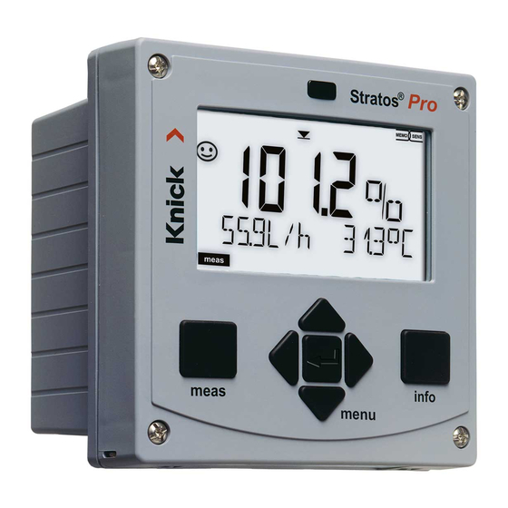
- Page 1 Stratos®Pro A401B PH User Manual Latest Product Information: www.knick.de 094698...
-
Page 2: Basics
Basics Copyright 2018 · Subject to change without notice. Return of products under warranty Please contact our Service Team before returning a defective device. Ship the cleaned device to the address you have been given. If the device has been in contact with process fluids, it must be de- contaminated/disinfected before shipment. -
Page 3: Documents Supplied
Documents Supplied Safety Instructions Quickstart Guides Installation and first steps: • Operation • Menu structure • Calibration • Error messages and recommended actions Specific Test Report Control Drawings Up-to date documentation available on our website: www.knick.de... -
Page 4: Table Of Contents
Basics ........................2 Documents Supplied ..................3 Introduction ..................... 7 Intended Use ....................7 Safety Information ................12 Overview of Stratos Pro A401B PH ............ 14 Assembly ....................15 Package Contents ..................15 Mounting Plan, Dimensions ..............16 Pipe Mounting, Protective Hood ............17 Panel Mounting .....................18 Installation .................... - Page 5 Contents Configuration ..................46 Parameter Set A/B ..................48 Parameter Sets (Original for Copy) ............56 Sensor .......................60 Current Output 1 ..................76 Current Output 2 ..................84 Temperature Compensation ..............86 CONTROL Input .....................90 Alarm Settings ....................94 Limit Function ....................98 Pulse Length / Pulse Frequency Controller........107 Controller ....................
- Page 6 Contents Operating States ..................147 Product Line and Accessories ............149 Specifications ..................150 Buffer Tables ..................158 -U1- Specifiable Buffer Set ..............168 Error Handling ..................171 Error Messages ..................172 Sensoface ....................175 FDA 21 CFR Part 11 ................178 Electronic Signature – Passcodes ............178 Audit Trail .....................
-
Page 7: Introduction
Introduction Intended Use Stratos Pro A401B PH is used for pH/mV, ORP and temperature measurement in industry, environment, food processing and sewage treatment. Enclosure and mounting possibilities • The sturdy molded enclosure is rated IP 67/NEMA 4X for outdoor use. It is made of glass-reinforced PBT / PC and measures 148 mm x 148 mm x 117 mm (H x W x D). - Page 8 Introduction Display Plain-text messages in a large, backlit LC display allow intuitive operation. You can specify which values are to be displayed in standard measuring mode (“Main Display”, see page 38). Color-coded user interface The colored display backlighting signals different operating states (e.g.
-
Page 9: Power Supply
Introduction Control inputs I input Current The analog (0) 4 ... 20 mA current input can be used for external temperature compen- input sation (TAN required). See page 88. HOLD HOLD (floating digital control input) The HOLD input can be used for external input activation of the HOLD mode, see page 44. -
Page 10: Relay Contacts
Introduction Signal outputs The device provides two current outputs (for transmission of measured value and temperature, for example). Relay contacts Four floating relay contacts are available. Current outputs Output 1 The floating current outputs (0) 4 ... 20 mA are used for transmitting measured values. An output filter can be programmed, the fault current value can be specified. - Page 11 Typical Application of Stratos Pro A401B PH...
-
Page 12: Safety Information
Safety Information Be sure to read and observe the following safety instructions! The device has been manufactured using state of the art technology and it complies with applicable safety regulations. When operating the device, certain conditions may nevertheless lead to danger for the operator or damage to the device. See also separate “Safety Instructions“... - Page 13 For orientation, please refer to NFPA 70 (NEC), ANSI/ISA-RP12.06.01. • When installing the device in a hazardous location, observe the specifications of the Control Drawing (download: www.knick.de). • Before commissioning, you must provide proof that the device may be connected with other equipment, such as a supply unit includ- ing cables and wires.
-
Page 14: Overview Of Stratos Pro A401B Ph
Overview Overview of Stratos Pro A401B PH pH / mV / + Output 1/HART Output 1 Measure el. temp input Reference el. – Output 1/HART Output 2 + Output 2 ISFET +3 V /–3 V – Output 2 +3 V... -
Page 15: Assembly
Assembly Package Contents Check the shipment for transport damage and completeness! The package should contain: • Front unit, rear unit, bag containing small parts • Specific test report • Documentation (cf p. 3) Fig.: Assembling the enclosure 1) Jumper (3 x) 6) Sealing insert (1 x) 2) Washer (1 x), for conduit 7) Rubber reducer (1 x) -
Page 16: Mounting Plan, Dimensions
Assembly Mounting Plan, Dimensions 1) Cable gland (3 x) 2) Knockouts for cable gland or ½” conduit, 21.5 mm dia. (2 knockouts) Conduits not included! 3) Knockout for pipe mounting (4 x) 4) Knockout for wall mounting (2 x) Fig.: Mounting plan (All dimensions in mm!) -
Page 17: Pipe Mounting, Protective Hood
Assembly Pipe Mounting, Protective Hood ø40...ø60 1) Hose clamp with worm gear drive to DIN 3017 (2 x) 2) Pipe-mount plate (1 x) 3) For vertical or horizontal posts or pipes 4) Self-tapping screw (4 x) Fig.: Pipe-mount kit, accessory ZU 0274 (All dimensions in mm!) Fig.: Protective hood for wall and pipe mounting, accessory ZU 0737 (All dimensions in mm!) -
Page 18: Panel Mounting
Assembly Panel Mounting < 30 1) Circumferential sealing (1 x) 2) Screws (4 x) 3) Position of control panel 4) Span piece (4 x) 5) Threaded sleeve (4 x) Cutout 138 x 138 mm (DIN 43700) 1...22 Fig.: Panel-mount kit, accessory ZU 0738 (All dimensions in mm!) -
Page 19: Installation
Installation Safety Precautions for Installation • Installation of the device must be carried out by trained experts in accordance with this user manual and as per applicable local and national codes. • Be sure to observe the technical specifications and input ratings during installation! •... -
Page 20: Rating Plates / Terminal Assignments
+55 °C Enclosure Type 4X 14163 Berlin Made in Germany Power: 00000 / 0000000 / 1845 Type A4**B-*/* 24 (-15%) to 230 (+10%) V AC, 45 to 65 Hz, < 12 VA APPROVED Installation 24 (-15%) to 80 (+10%) V DC , 4 W - 20 <... -
Page 21: Power Supply, Signal Lines
Power Supply, Signal Lines Connect the power supply for Stratos Pro A401B PH to terminals 21 and 22 (24 ... 230 V AC, 45 ... 65 Hz / 24 ... 80 V DC) Terminal assignments Areas for placing the screwdriver to pull out the terminals Fig.: Terminals, device opened, back of front unit... -
Page 22: Connecting The Sensor
Connecting the Sensor Connect the sensor lines with the sensor connection terminals (module terminals A...K). Sensor connection MK-PH module Areas for placing the screwdriver to pull out the terminals Fig.: Terminals, device opened, back of front unit... -
Page 23: Wiring Examples
Wiring Examples Example 1: Measuring task: pH, temperature, glass impedance Sensors (example): SE 555X/1-NS8N Cable (example): ZU 0318 Jumper! - Page 24 Wiring Examples Example 2: Measuring task: pH/ORP, temp, glass impedance, ref. impedance Sensors (example): SE555X/1-NS8N, equipotential bonding: ZU 0073 Temperature: e.g. Pt1000 Cable (example): 2x ZU 0318...
- Page 25 Wiring Examples Example 3: Measuring task: pH, temp, glass impedance Sensors (example): pH sensor, e.g., SE 554X/1-NVPN, Cable CA/VP6ST-003A Integrated temperature detector Jumper!
- Page 26 Wiring Examples Example 4: Measuring task: pH/ORP, temp, glass impedance, ref. impedance Sensors (example): pH sensor, e.g., SE 555X/1-NVPN, cable CA/VP6ST-003A Integrated temperature detector Equipotential bonding electrode ZU 0073, cable: ZU 0318...
- Page 27 Wiring Examples Example 5: Measuring task: pH/ORP, temp, glass impedance, ref. impedance Sensors (example): PL PETR-120VP (pH/ORP combo sensor, SI Analytics) Cable (example): CA/VP6ST-003A...
- Page 28 Wiring Examples Example 6: NOTICE! Do not connect an additional analog sensor! Measuring task: pH/ORP, temp, glass impedance, ref. impedance Sensors (example): ISM digital InPro 4260i (Mettler-Toledo) Cable (example): AK9 (Mettler-Toledo)
- Page 29 Wiring Examples Example 7 – Note: Switch off Sensocheck! Measuring task: ORP, temp, glass impedance, ref. impedance Sensors (example): ORP: SE 564X/1-NS8N Cable (example): ZU 0318 Jumper!
- Page 30 Wiring Examples Example 8: Connecting a Pfaudler probe (TAN SW-A007 required): Device pH Reiner Differential Models 03/04 Models 03/04 with equipoten- Models 18/40 with equipoten- without equi- tial bonding, with equipoten- tial bonding potential VP screw cap tial bonding bonding meas Coax core Coax WH...
- Page 31 Wiring Examples Example 9: Memosens Measuring task: pH/ORP, temp, glass impedance, ref. impedance Sensors (example): SE 554X/1-AMSN (Memosens combo sensor) Cable (example): CA/MS-003NAA...
-
Page 32: Protective Wiring Of Relay Contacts
Protective Wiring of Relay Contacts Relay contacts are subject to electrical erosion. Especially with inductive and capacitive loads, the service life of the contacts will be reduced. For suppression of sparks and arcing, components such as RC combinations, nonlinear resistors, series resistors and diodes should be used. - Page 33 Protective Wiring of Relay Contacts Typical Protective Wiring Measures DC application with inductive load AC/DC applications with capacitive load Connection of incandescent lamps Inductive load Free-wheeling diode, e.g. 1N4007 (Observe polarity) Contact Capacitive load Resistor, e.g. 8 Ω / 1 W at 24 V / 0.3 A Contact Incandescent lamp, max 60 W / 230 V, 30 W / 115 V Contact...
-
Page 34: User Interface, Keypad
User Interface, Keypad MEMO SENS 1 IrDA transmitter/receiver 2 Display 3 Keypad 4 Rating plate (enclosure bottom) Function • Return to last menu level • Directly to measuring mode (press > 2 s) • Measuring mode: other display • Retrieve information •... -
Page 35: Display
Display MEMO SENS 1 Temperature 13 Info available 2 Sensocheck 14 Hold mode active 3 Interval/response time 15 Main display 4 Sensor data 16 Secondary display 5 Not used 17 Proceed using enter 6 Limit message: 18 ISM sensor Limit 1 or Limit 2 19 Diagnostics 7 Alarm... -
Page 36: Measuring Mode
Measuring Mode After the operating voltage has been connected, the analyzer auto- matically goes to “Measuring“ mode. To call the measuring mode from another operating mode (e.g. Diagnostics, Service): Hold meas key depressed (> 2 s). Sensoface indicator Active (sensor status) parameter set (configuration) Time... -
Page 37: Selecting The Mode / Entering Values
Selecting the Mode / Entering Values To select the operating mode: 1) Hold meas key depressed (> 2 s) (directly to measuring mode) 2) Press menu key: the selection menu appears 3) Select operating mode using left / right arrow key 4) Press enter to confirm the selected mode Selection menu Selected mode... -
Page 38: Display In Measuring Mode
Display in Measuring Mode The MAIN DISPLAY is the display which is shown in measuring mode. To call the measuring mode from any other mode, hold the meas key depressed for at least 2 sec. meas key enter key By pressing meas briefly you can step through further displays such as tag number (TAG) or flow (L/h). -
Page 39: Color-Coded User Interface
Color-Coded User Interface The color-coded user interface guarantees increased operating safety. Operating modes are clearly signaled. The normal measuring mode is white. Information text appears on a green screen and the diagnostic menu appears on turquoise. The orange HOLD mode (e.g. during calibration) is quickly visible as is the magenta screen which indicates asset management messages for predictive diagnostics –... -
Page 40: Operating Modes
Operating Modes Diagnostics Display of calibration data, display of sensor data, performing a device self-test, viewing the logbook entries, display of hardware/software ver- sions of the individual components. The logbook can store 100 events (00...99). They can be displayed directly on the device. The logbook can be extended to 200 entries using a TAN (Option). -
Page 41: Menu Structure Of Modes And Functions
Menu Structure of Modes and Functions Controller meas meas meas meas Meas. mode TAG display CLK display parameter display (main display selectable) (if configured) after 60 s after 60 s Pressing the menu key (down arrow) opens the selection menu. Select the menu group using the left/right arrow keys. -
Page 43: Hold Mode
HOLD Mode The HOLD mode is a safety state during configuration and calibration. Output current is frozen (LAST) or set to a fixed value (FIX). The HOLD mode is indicated by orange display backlighting. HOLD mode, display icon: Output signal response •... -
Page 44: Alarm
Alarm External activation of HOLD (SW-A005) The HOLD mode can be activated from outside by sending a signal to the HOLD input (e.g. from the process control system). Power supply HOLD 12...24 V AC/DC input Stratos Pro A4... Process control system HOLD inactive 0...2 V AC/DC HOLD active... -
Page 45: Alarm And Hold Messages
Alarm and HOLD Messages Message Released by Cause Alarm Sensocheck Polarization / Cable (22 mA) Error messages Flow (CONTROL input) Alarm ERR 10: ORP display range violation contact < -1999 mV or > 1999 mV opens HOLD HOLD HOLD via menu or input (Last/Fix) CONF Configuration... -
Page 46: Configuration
Configuration The configuration steps are assigned to different menu groups. With the left/right arrow keys you can jump between the individual menu groups. Each menu group contains menu items for setting the parameters. Pressing enter opens a menu item. Use the arrow keys to edit a value. Press enter to confirm/save the settings. - Page 47 Configuration Parameter set A/B: configurable menu groups The device provides 2 parameter sets “A“ and “B“. By switching between the param- eter sets you can adapt the device to different measurement situations, for example. Parameter set “B“ only permits setting of process-related parameters. Menu group Parameter set A Parameter set B...
-
Page 48: Parameter Set A/B
Configuration Parameter Set A/B Manual Selection. Signaling via WASH Contact. Display Action Remark To switch between Manual selection of parameter sets must have parameter sets: been preset in CONFIG Press meas. mode. Default setting is a fixed parameter set A. Wrong settings change the measurement properties! - Page 49 Configuration Configuration Select Default Sensor (SENSOR) (omitted for ISM) (EXT. only with I-input enabled via TAN) (EXT. only with I-input enabled via TAN) Note: Pressing info displays nominal buffer values + manufacturer (For specifiable Enter values for buffer 1 buffer set, see Appendix: “Buffer Tables“) Enter values for buffer 2...
- Page 50 Configuration Configuration Select Default Sensor (SENSOR) (for ISM sen- sors only)
- Page 51 Configuration Configuration Select Default Output 1 (OUT1) Select °C / °F at "Sensor“ Output 2 (OUT2) Select °C / °F at "Sensor“...
- Page 52 Configuration Configuration Select Default Temperature compensation (CORRECTION) TC SELECT OFF / LIN / PURE WTR / USER TAB TC LIQUID -19.99 ... 19.99 %/K 00.00 %/K USERTAB EDIT TABLE NO/YES TC xxx °C 0 ... 100 °C in 5K Control input (CNTR_IN) Parameter-set switchover (PARSET) flow measurement...
- Page 53 Configuration Configuration Choices Default Relay 1/2 (RL1/RL2) (Selected in text line)
- Page 54 Configuration Configuration Choices Default Cleaning contact (WASH) (Select text line) Parameter set (PARSET) Select fixed parameter set PARSET FIX (A) or switch between A/B (fixed parameter via control input or manu- set A) ally in measuring mode Real-time clock (CLOCK) Tag number (TAG) (Input in text line)
- Page 55 Configuration Support of Pfaudler Sensors or pH sensors with a zero point other than pH 7 and/or deviating slope, e.g. pH sensors with a zero point at pH 4.6 This requires an additional function (TAN). The option is enabled in the SERVICE / OPT: PFAUDLER menu (see page 148).
-
Page 56: Parameter Sets (Original For Copy)
Parameter Sets (Original for Copy) Two complete parameter sets are stored in the EEPROM. As delivered, the two sets are identical but can be edited. Note: Fill in your configuration data on the following pages or use them as original for copy. Parameter Parameter set A Parameter set B... - Page 57 Parameter Sets (Original for Copy) Parameter Parameter set A Parameter set B OT1: Current start OT1: Current end OT1: Filter time OT1: 22 mA error current OT1: Sensoface 22mA error current OT1: HOLD mode OT1: HOLD-FIX current OT2: Current range OT2: Process variable OT2: Current start OT2: Current end OT2: Filter time...
- Page 58 Parameter Sets (Original for Copy) Parameter Parameter set A Parameter set B REL: Usage RL1: Process variable RL1: Function RL1: Contact response RL1: Setpoint RL1: Hysteresis RL1: Delay RL2: Process variable RL2: Function RL2: Contact response RL2: Setpoint RL2: Hysteresis RL2: Delay CTR: Process variable CTR: Controller type...
- Page 59 Parameter Sets (Original for Copy) Parameter Parameter set A Parameter set B CLK: Time format CLK: Time hh/mm CLK: Day/month CLK: Year TAG: Tag number *) These parameters cannot be adjusted in parameter set B, the values are the same as in parameter set A.
-
Page 60: Sensor
Configuration Sensor Select: sensor type, temperature probe, temperature unit, temp detection during measurement 1) Press menu key. 2) Select CONF using keys, press enter. 3) Select parameter set using , press enter. 4) Select SENSOR menu using keys, press enter. - Page 61 Configuration Menu item Action Choices Select sensor type Select sensor type using keys. Digital sensors: Press enter to confirm. Select type of temp (not for digital sensors) Select type of tempera- probe ture probe using keys. Press enter to confirm. Temperature unit Select °C or °F using ...
- Page 62 Configuration Sensor Select: temp detection during calibration, calibration mode 1) Press menu key. 2) Select CONF using keys, press enter. 3) Select parameter set using , press enter. 4) Select SENSOR menu using keys, press enter. 5) All items of this menu group are indicated by the “SNS:”...
-
Page 63: Calibration Mode
Configuration Menu item Action Choices Temp detection Select mode using keys: during calibration AUTO: Measured by sensor MAN: Direct input of temperature, no measure- ment (see next step) EXT: Temperature speci- fied via current input (only if TAN E enabled) Press enter to confirm. - Page 64 Configuration Sensor Adjust: Cal timer, cal cycle 1) Press menu key. 2) Select CONF using keys, press enter. 3) Select parameter set using , press enter. 4) Select SENSOR menu using keys, press enter. 5) All items of this menu group are indicated by the “SNS:”...
- Page 65 Configuration Menu item Action Choices Calibration timer Adjust CALTIMER using keys: OFF: No timer With ADAPT, the calibra- ADAPT: Maximum cal tion cycle is automatically cycle (adjust in the next reduced depending on step) the sensor load (high FIX: Fixed cal cycle (adjust temperatures and pH in the next step) values) and for digital...
- Page 66 Configuration ISM Sensor Adaptive cal timer (ACT) 1) Press menu key. 2) Select CONF using keys, press enter. 3) Select parameter set using keys, press enter. 4) Select SENSOR menu using keys, press enter. 5) All items of this menu group are indicated by the “SNS:”...
- Page 67 Configuration Adaptive Calibration Timer (ACT) By issuing a Sensoface message, the adaptive calibration timer reminds you to calibrate the sensor. After expiration of the ACT in- terval, Sensoface is getting “sad”. Pressing the info key shows the text “OUT OF CAL TIME CALIBRATE SENSOR” which reminds you that a calibration is due.
- Page 68 Configuration ISM Sensor Adaptive Maintenance Timer (TTM) 1) Press menu key. 2) Select CONF using keys, press enter. 3) Select parameter set using keys, press enter. 4) Select SENSOR menu using keys, press enter. 5) All items of this menu group are indicated by the “SNS:”...
- Page 69 Configuration Adaptive Maintenance Timer (TTM, Time To Maintenance) By issuing a Sensoface message, the adaptive maintenance timer reminds you to service the sensor. After expiration of the interval, Sensoface is getting “sad”. Pressing the info key shows the text “OUT OF MAINTENANCE CLEAN SENSOR” which reminds you that a sensor maintenance is due.
- Page 70 Configuration Standard and ISFET Sensor Adjust: CIP cleaning cycles, SIP sterilization cycles 1) Press menu key. 2) Select CONF using keys, press enter. 3) Select parameter set using keys, press enter. 4) Select SENSOR menu using keys, press enter.
- Page 71 Configuration Menu item Action Choices CIP / SIP The following adjustments are possible for standard and ISFET sensors: Cleaning cycles Select ON or OFF using ON/OFF keys. When switched on, the cycles will be entered in the extended logbook but not counted.
- Page 72 Configuration ISM Sensor Adjust: CIP cleaning cycles, SIP sterilization cycles 1) Press menu key. 2) Select CONF using keys, press enter. 3) Select parameter set using keys, press enter. 4) Select SENSOR menu using keys, press enter. 5) All items of this menu group are indicated by the “SNS:”...
- Page 73 Configuration Menu item Action Choices CIP / SIP The following adjustments are possible for ISM sensors : Cleaning cycle Select ON or OFF using ON/OFF keys. counter Press enter to confirm. Cleaning cycles Only with CIP COUNT ON: 0...9999 CYC (0000 CYC) Enter value using ...
- Page 74 Configuration ISM Sensor Autoclaving counter 1) Press menu key. 2) Select CONF using keys, press enter. 3) Select parameter set using keys, press enter. 4) Select SENSOR menu using keys, press enter. 5) All items of this menu group are indicated by the “SNS:”...
- Page 75 Configuration Autoclaving Counter After reaching a specified limit value the autoclaving counter gen- erates a Sensoface message. As soon as the counter has reached the specified value, Sensoface is getting “sad”. Pressing the info key shows the text “AUTOCLAVE CYCLES OVERRUN” which reminds you that the maximum number of autoclaving cycles has been reached.
-
Page 76: Current Output 1
Configuration Current Output 1 Output current range. Current start. Current end. 1) Press menu key. 2) Select CONF using keys, press enter. 3) Select parameter set using keys, press enter. 4) Select OUT1 menu using keys, press enter. - Page 77 Configuration Menu item Action Choices Current range Select 4-20 mA or 0-20 mA range using keys. Press enter to confirm. Process variable Select using keys: PH: pH value ORP: Redox potential TMP: Temperature Press enter to confirm. Current start Modify digit using ...
- Page 78 Configuration Current Output 1 Adjusting the time interval of the output filter 1) Press menu key. 2) Select CONF using keys, press enter. 3) Select parameter set using keys, press enter. 4) Select OUT1 menu using keys, press enter.
- Page 79 Configuration Menu item Action Choices Time averaging filter Enter value using keys. Press enter to confirm. Time averaging filter To smoothen the current output, a low-pass filter with adjustable filter time constant can be switched on. When there is a jump at the input (100 %), the output level is at 63 % after the time interval has been reached.
- Page 80 Configuration Current Output 1 Output current for error message or Sensoface alert 1) Press menu key. 2) Select CONF using keys, press enter. 3) Select parameter set using keys, press enter. 4) Select OUT1 menu using keys, press enter.
- Page 81 Configuration Menu item Action Choices Output current for In the case of an error (FAIL), the current output is error message (FAIL) set to 22 mA. Select ON or OFF using keys. Press enter to confirm. Output current for In the case of a Sensoface alert (FACE), the current Sensoface (FACE)
- Page 82 Configuration Current Output 1 Output current during HOLD 1) Press menu key. 2) Select CONF using keys, press enter. 3) Select parameter set using keys, press enter. 4) Select OUT1 menu using keys, press enter. 5) All items of this menu group are indicated by the “OT1:”...
- Page 83 Configuration Menu item Action Choices Output current LAST/FIX LAST: During HOLD the last measured value is during HOLD maintained at the output. FIX: During HOLD a value (to be entered) is main- tained at the output. Select using Press enter to confirm. Output current for Only with FIX selected: 00.00...22.00 mA...
-
Page 84: Current Output 2
Configuration Current Output 2 Output current range. Current start. Current end ... 1) Press menu key. 2) Select CONF using keys, press enter. 3) Select parameter set using keys, press enter. 4) Select OUT2 menu using keys, press enter. - Page 85 Configuration Menu item Action Choices Current range Select 4-20 mA or 0-20 mA range using keys. Press enter to confirm. Process variable Select using keys: PH: pH value ORP: Redox potential TMP: Temperature Press enter to confirm. All the following adjustments are made as for current output 1 (see page 76)!
-
Page 86: Temperature Compensation
Configuration Temperature Compensation TC process medium: Linear, ultrapure water, table 1) Press menu key. 2) Select CONF using keys, press enter. 3) Select parameter set using keys, press enter. 4) Select CORRECTION menu using keys, press enter. 5) All items of this menu group are indicated by the “COR:”... - Page 87 Configuration Menu item Action Choices Temp compensation, For pH measurement only: Select temperature process medium compensation of the process medium. Linear: LIN Ultrapure water: PUREWTR Table: USERTAB Select using key, proceed using enter. Temperature Enter the linear tempera- ture compensation of the compensation, linear process medium.
- Page 88 Configuration Temperature Compensation Current input, external temp measurement 1) Press menu key. 2) Select CONF using keys, press enter. 3) Select parameter set using keys, press enter. 4) Select CORRECTION menu using keys, press enter. 5) All items of this menu group are indicated by the “COR:”...
- Page 89 Configuration Menu item Action Choices Current input, Only if enabled via TAN and selected during external temp configuration (SENSOR). measurement Select ON or OFF using keys. Press enter to confirm. Current range Select desired range using keys. Press enter to confirm. Current start Input range: Modify digit using ...
-
Page 90: Control Input
Configuration CONTROL Input Parameter set selection via external signal or flow measurement 1) Press menu key. 2) Select CONF using keys, press enter. 3) Select parameter set using , press enter. 4) Select CNTR_IN menu using keys, press enter. - Page 91 Configuration Menu item Action Choices Select function of Select using keys. Press enter to confirm. CONTROL input (selecting parameter set A/B via signal at CONTROL input) External switchover of parameter sets The parameter set A/B can be activated from outside by sending a signal to the CONTROL input (e.g.
- Page 92 Configuration CONTROL Input Flow measurement 1) Press menu key. 2) Select CONF using keys, press enter. 3) Select parameter set using , press enter. 4) Select CNTR_IN menu using keys, press enter. 5) All items of this menu group are indicated by the “IN:”...
- Page 93 Configuration Menu item Action Choices Select function of PARSET Select using keys. (selecting parameter Press enter to confirm. CONTROL input set A/B via signal at CONTROL input) Flow (for connecting a pulse- output flow meter) Adjust to flow meter With "Flow"...
-
Page 94: Alarm Settings
Configuration Alarm Settings Alarm delay. Sensocheck. 1) Press menu key. 2) Select CONF using keys, press enter. 3) Select parameter set using keys, press enter. 4) Select ALARM menu using keys, press enter. 5) All items of this menu group are indicated by the “ALA:”... - Page 95 Configuration Menu item Action Choices Alarm delay Enter value using keys. Press enter to confirm. Sensocheck Select Sensocheck (continuous monitoring of glass and reference electrode) Select ON or OFF using keys. Press enter to confirm. (At the same time, Sensoface is activated.
- Page 96 Configuration Alarm Settings CONTROL input (FLOW MIN, FLOW MAX) 1) Press menu key. 2) Select CONF using keys, press enter. 3) Select parameter set using keys, press enter. 4) Select ALARM menu using keys, press enter. 5) All items of this menu group are indicated by the “ALA:”...
- Page 97 Configuration Menu item Action Choices CONTROL input The CONTROL input can generate an alarm when assigned to FLOW (flow monitoring) in the CONF menu: FLOW CNTR Flow measurement: allows monitoring the minimum and maximum flow (pulse counter) Alarm Specify value Default: 05.00 liters/h Minimum flow FLOW MIN...
-
Page 98: Limit Function
Configuration Limit Function Relay 1 1) Press menu key. 2) Select CONF using keys, press enter. 3) Select parameter set using keys, press enter. 4) Select REL1/REL2 menu using keys, press enter. 5) All items of this menu group are indicated by the “RL1:”... - Page 99 Configuration Menu item Action Choices Use of relays Select in the text line using keys: • Limit function (LIMITS) • Controller Note: Selecting (CONTROLLER) CONTROLLER leads to Controller menu group Press enter to confirm. CTR. Select process Select desired process variable using ...
- Page 100 Configuration Limit Function Relay 1 1) Press menu key. 2) Select CONF using keys, press enter. 3) Select parameter set using keys, press enter. 4) Select REL1/REL2 menu using keys, press enter. 5) All items of this menu group are indicated by the “RL1:”...
- Page 101 Configuration Menu item Action Choices Limit 1 hysteresis Select hysteresis using keys. Press enter to confirm. Limit 1 delay The contact is activated with delay (deactivated without delay) Adjust delay using keys. Press enter to confirm. Application of hysteresis: Limit Lo Limit Hi...
- Page 102 Configuration Limit Function Relay 2 1) Press menu key. 2) Select CONF using keys, press enter. 3) Select parameter set using keys, press enter. 4) Select REL1/REL2 menu using keys, press enter. 5) All items of this menu group are indicated by the “RL2:”...
- Page 103 Configuration Menu item Action Choices Select process Select desired process variable using keys. variable Press enter to confirm. (CHANNEL) Limit 2 function Select desired function using arrow keys. (FUNCTION) Press enter to confirm. Limit 2 icon: Limit 2 contact type N/O: normally open contact (CONTACT)
- Page 105 Controller Functions Typical applications P controller Application for integrating control systems (e.g. closed tank, batch processes). PI controller Application for non-integrating control systems (e.g. drains). PID controller The additional derivative action compensates for measurement peaks. Controller characteristic +100 % Controller output Yp [%] Relay 1 Neutral zone Yp=0...
- Page 106 Controller Functions Controller equations Controller output Y = P action I action D action with: Proportional action Proportional action Y Reset time [s] Rate time [s] Setpoint - Meas. value Controller gain [%] Constant Constant 5 (for pH) 500 mV (for ORP) Neutral zone Tolerated deviation from desired value.
-
Page 107: Pulse Length / Pulse Frequency Controller
Controller Functions Pulse Length / Pulse Frequency Controller Pulse length controller (PLC) The pulse length controller is used to operate a valve as an actuator. It switches the contact on for a time that depends on the controller output. The period (pulse length) is constant. A minimum ON time of 0.5 sec is maintained even if the controller output takes correspond- ing values (Y=0: Off ). -
Page 108: Controller
Configuration Controller (For description, see Controller Functions) Process variable. Controller type. Setpoint. 1) Press menu key. 2) Select CONF using keys, press enter. 3) Select parameter set using keys, press enter. 4) Select REL1/REL2 menu using keys, press enter. - Page 109 Configuration Menu item Action Choices Use of relays Select in the text line using keys: • CONTROLLER Selecting CONTROLLER leads to Controller menu Press enter to confirm. group CTR. Select process Select desired process variable using keys. variable Press enter to confirm.
- Page 110 Configuration Controller (For description, see Controller Functions) Neutral zone. P, I, D actions. Behavior during HOLD 1) Press menu key. 2) Select CONF using keys, press enter. 3) Select parameter set using keys, press enter. 4) Select REL1/REL2 menu using keys, press enter.
- Page 111 Configuration Menu item Action Choices Neutral zone Adjust neutral zone using keys. Press enter to confirm. Controller: P action Adjust P action using keys. Press enter to confirm. Controller: I action Adjust I action using ...
-
Page 112: Wash Contact
Configuration WASH Contact Control of rinsing probes or signaling the parameter set 1) Press menu key. 2) Select CONF using keys, press enter. 3) Select parameter set A using keys, press enter. 4) Select WASH menu using keys, press enter. - Page 113 Configuration Menu item Action Choices Function WASH / PARSET A/B Select WASH contact function using keys. WASH: Control of rinsing probes With PARSET A/B selected, the contact signals: “Parameter set A“ (open contact) “Parameter set B“ (closed contact) Press enter to confirm. Cleaning interval 0.0...999.9 h (000.0 h) Only with WASH:...
-
Page 114: Time And Date
Configuration Time and Date Tag Number 1) Press any arrow key. 2) Select CONF using keys, press enter. 3) Select parameter set A using keys, press enter. 4) Select CLOCK or TAG using keys, press enter. 5) All items of this menu group are indicated by the “CLK:”... - Page 115 Configuration Time and Date Control of the calibration and cleaning cycles is based on the time and date of the integrated real-time clock. In measuring mode the time is shown in the lower display. When using digital sensors, the calibration data is written in the sensor head.
-
Page 116: Digital Sensors
Digital Sensors Stratos Pro can be operated with digital sensors. Due to the galvanic isolation of Memosens sensors, earth or ground potentials have no effect here. Therefore, a Solution Ground or measures for equipotential bonding are not required. Digital sensors can be calibrated and maintained in the lab. This considerably simplifies on-site maintenance. -
Page 117: Memosens Sensors: Configuring The Device
Calibration history of several sensors function) or “Advanced“ (with sensor database) version: www.knick.de History: Load diagrams of the sensors Memosens Sensors: Configuring the Device The sensor type is selected during Configuration. The device only switches to measuring mode when the connected sensor corresponds to the type configured (Sensoface is friendly): Otherwise, an error message is released. -
Page 118: Replacing A Sensor
Digital Sensors Connecting a Digital Sensor Step Action/Display Remark Connect sensor Before a digital sensor is connected, the error message “No sensor“ is displayed. Wait until the The hourglass in the display blinks. sensor data are MEMO SENS displayed. Check sensor Display color changes to green. - Page 119 Digital Sensors Step Action/Display Remark Press menu key to call Select HOLD Now the device is in HOLD mode. The HOLD mode can also mode the selection menu, be activated externally via the select HOLD using the HOLD input. During HOLD the keys, press enter output current is frozen at its last to confirm.
-
Page 120: Calibration
Calibration NOTICE: • All calibration procedures must be performed by trained person- nel. Incorrectly set parameters may go unnoticed, but change the measuring properties. • The response time of the sensor and temperature probe is considerably reduced when the sensor is first moved about in the buffer solution and then held still. -
Page 121: Selecting A Calibration Mode
Selecting a Calibration Mode Calibration is used to adapt the device to the individual sensor characteristics, namely asymmetry potential and slope. Access to calibration can be protected with a passcode (SERVICE menu). First, you open the calibration menu and select the calibration mode: CAL_PH Depending on configuation setting: AUTO... -
Page 122: Zero Adjustment (Isfet)
Zero adjustment Zero Adjustment (ISFET) This adjustment allows the use of ISFET sensors with differing nominal zero (pH only). The function is available when Sensor selection = ISFET has been set during configuration. Zero adjustment is disabled for any other sensors. The adjustment is made using a zero buffer (pH 7.00). - Page 123 Zero Adjustment (ISFET) Display Action Remark At the end of the ad- This is not the final justment procedure calibration value of the zero offset [mV] of the sensor! Asym- the sensor is displayed metry potential (based on 25 °C). and slope must be Sensoface is active.
-
Page 124: Automatic Calibration (Calimatic)
Adjustment (Calimatic) Automatic Calibration (Calimatic) The AUTO calibration mode and the type of temperature detection are selected during configuration. Make sure that the buffer solutions used correspond to the configured buffer set. Other buffer solutions, even those with the same nominal values, may demonstrate a differ- ent temperature response. - Page 125 Automatic Calibration (Calimatic) Display Action Remark Note: At the end of the stabil- ity check, the value will Stability check can be saved and the asym- be stopped after metry potential will be 10 sec (by pressing displayed. enter). However, this Calibration with the first reduces calibration buffer is terminated.
-
Page 126: Manual Calibration With Buffer Entry
Manual Calibration with Buffer Entry The MAN calibration mode and the type of temperature detection are selected during configuration. For calibration with manual buffer specification, you must enter the pH value of the buffer solution used in the device for the proper temperature. Any desired buffer solution can be used for calibration. - Page 127 Manual Calibration with Buffer Entry Display Action Remark Note: At the end of the stabil- ity check, the value will Stability check can be saved and the asym- be stopped after metry potential will be 10 sec (by pressing enter). However, this displayed.
-
Page 128: Data Entry Of Premeasured Sensors
Data Entry of Premeasured Sensors The DAT calibration mode must have been preset during configuration. You can directly enter the values for slope and asymmetry potential of a sensor. The values must be known, e.g. determined beforehand in the laboratory. Display Action Remark... - Page 129 Converting Slope to mV Converting slope [%] to slope [mV/pH] at 25 °C mV/pH 46.2 47.4 48.5 49.7 50.9 52.1 53.3 54.5 55.6 56.8 58.0 100 59.2 102 60.4 Converting asymmetry potential to sensor zero point [mV] ZERO = 7 - = Sensor zero ZERO S [mV / pH]...
-
Page 130: Product Calibration (Ph)
Product calibration Product Calibration (pH) Calibration by sampling (one-point calibration). During product calibration the sensor remains in the process. The measurement process is only interrupted briefly. Procedure: 1) The sample is measured in the lab or directly on the site using a por- table meter. - Page 131 Product Calibration (pH) Display Action Remark The device returns to From the blinking measuring mode. CAL mode indicator you see that product calibration has not been terminated. Product calibration Display (3 sec) step 2 Now the device is in HOLD mode. The stored value is displayed (blinking) and can be overwritten with...
-
Page 132: Orp (Redox) Calibration
ORP (Redox) Calibration The potential of a redox sensor is calibrated using a redox (ORP) buffer solution. In the course of that, the difference between the measured potential and the potential of the calibration solution is determined according to the following equation. During measurement this differ- ence is added to the measured potential. -
Page 133: Orp Calibration
ORP Calibration Display Action Remark Select ORP calibration, proceed with enter Remove the sen- Display (3 sec) sor and temperature Now the device is in probe, clean them, and HOLD mode. immerse them in the redox buffer. Enter setpoint value for redox buffer. -
Page 134: Temp Probe Adjustment
Temp probe adjustment Temp Probe Adjustment Display Action Remark Select temp adjust- Wrong settings ment. Press enter to change the proceed. measurement properties! Measure the tempera- Display (3 sec) ture of the process me- Now the device is in dium using an external HOLD mode. -
Page 135: Measurement
Measurement Display Remark From the configuration or calibration menus, you can switch the device to measuring mode by pressing the meas key. In the measuring mode the main display shows the configured process variable (pH, or AM/PM and °F: ORP [mV], or temperature), the second- ary display shows the time and the second configured process variable (pH, ORP [mV], or temperature). - Page 136 Measurement Display Remark With activated controller you can also step through the following displays by pressing the meas key. When no key has been pressed for 60 sec, the device returns to the standard display. Upper display: Controller output Y Secondary display: Setpoint Depending on configuation setting: pH, mV, or temperature.
-
Page 137: Diagnostics
Diagnostics (DIAG) Diagnostics In the Diagnostics mode you can access the following menus without interrupting the measurement: CALDATA Viewing the calibration data SENSOR Viewing the sensor data SELFTEST Starting a device self-test LOGBOOK Viewing the logbook entries MONITOR Displaying currently measured values VERSION Displaying device type, software version, serial number Access to diagnostics can be protected with a passcode... - Page 138 Diagnostics Display Menu item Display of calibration data Select CALDATA using, confirm with enter. Use thekeys to select the desired parameter from the bottom line of the display (LAST_CAL ISFET-ZERO ZERO SLOPE NEXT_CAL). The selected parameter is shown in the main display. Press meas to return to measurement.
- Page 139 Diagnostics Display Menu item Device self-test (To abort, you can press meas.) 1) Display test: Display of all segments with changing background colors (white/green/red). Press enter to proceed. 2) RAM test: Hourglass blinks, then display of --PASS-- or --FAIL-- Press enter to proceed. 3) EEPROM test: Hourglass blinks, then display of --PASS-- or --FAIL-- Press enter to proceed.
- Page 140 Diagnostics Display Menu item Displaying the logbook entries Select LOGBOOK using, press enter to confirm. Using the keys, you can scroll backwards and forwards through the logbook (entries -00-...-99-), -00- being the last entry. If the display is set to date/time, you can search for a particular date using the ...
- Page 141 Diagnostics Display Menu item Display of currently measured values (sensor monitor) Select MONITOR using, press enter to confirm. Use the keys to select the desired parameter from the bottom line of the display: mV_PH mV_ORP RTD R_GLASS R_REF I-INPUT (for digital sensors also: OPERATION TIME SENSOR WEAR LIFETIME CIP SIP AUTOCLAVE, for ISM sensors in addition: ACT (adaptive calibration timer)
-
Page 142: Service
Service (SERVICE) A Service In the Service mode you can access the following menus: MONITOR Displaying currently measured values SENSOR ISM only: Resetting TTM Incrementing autoclaving counter OUT1 Testing current output 1 OUT2 Testing current output 2 RELAIS Testing the function of the 4 relays CONTROL Testing the controller function IRDA... - Page 143 Service Menu item Remark Displaying the currently measured values (sensor monitor) with HOLD mode activated: Select MONITOR using, press enter to confirm. Select variable in the bottom text line using. The selected parameter is shown in the main display. As the device is in HOLD mode, you can perform validations using simulators without influencing the signal outputs.
- Page 144 Service Menu item Remark Specifying the current at outputs 1 and 2: Select OUT1 or OUT2 using thekeys, press enter to confirm. Enter a valid current value for the respective output using keys. Press enter to confirm. For checking purposes, the actual output current is shown in the bottom right corner of the display.
- Page 145 Service Menu item Remark Controller test (manual specification of controller output): This function is used to start up control loops or check the actuators. For bumpless changeover to automatic operation (exiting this function), configure an I-action component (reset time). Controller characteristic The lower display shows the currently adjusted controller output Yp.
- Page 146 Service Menu item Remark Assigning passcodes: In the “SERVICE - CODES“ menu you can assign pass- codes to DIAG, HOLD, CAL, CONF, and SERVICE modes (Service preset to 5555). When you have lost the Service passcode, you have to request an “Ambulance TAN“ from the manufac- turer specifying the serial number of your device.
-
Page 147: Operating States
Operating states A Operating States Operating status Measuring DIAG 60 s CONF SERVICE SERVICE OUT 1 SERVICE OUT 2 SERVICE RELAY SERVICE CONTROL Cleaning fct HOLD Explanation: as configured (Last/Fix or Last/Off ) active manual... -
Page 149: Product Line And Accessories
Product Line and Accessories Order Code Stratos Pro A 4... Channel 1 Channel 2 Example 0 1 B - PH 4-wire / 20...254 V AC/DC B,C,E Communication Without (HART retrofittable via TAN) 0 Version number Version Approvals General Safety FM / CSA Zone 2 / Cl 1 Div 2 Meas. -
Page 150: Specifications
Manual calibration with entry of individual buffer values Data entry of pre-measured electrodes Product calibration Calimatic buffer sets -01- Mettler-Toledo 2.00/4.01/7.00/9.21 -02- Knick CaliMat 2.00/4.00/7.00/9.00/12.00 -03- Ciba (94) 2.06/4.00/7.00/10.00 -04- NIST technical 1.68/4.00/7.00/10.01/12.46 -05- NIST standard 1.679/4.006/6.865/9.180 -06- HACH 4.01/7.00/10.01... - Page 151 Specifications Zero adjustment ± 200 mV (for ISFET) Max. calibration range Asymmetry potential ±60 mV Slope 80 ... 103 % (47.5 ... 61 mV/pH) (possibly restricting notes from Sensoface) ORP sensor standardization ORP calibration (zero adjustment) Max. calibration range –700 ... +700 ΔmV Adaptive cal timer Interval 0000 ...
- Page 152 Specifications I input (TAN) Current input 0/4 ... 20 mA / 50 Ω for external temperature signal Start/end of scale Configurable –20 ... 200 °C (-4 ... 392 °F) Characteristic Linear Measurement error 1.3) < 1% current value + 0.1 mA HOLD input Galvanically separated (optocoupler) Function...
- Page 153 Specifications Output 2 0/4 ... 20 mA, max. 10 V, floating (galv. connected to output 1) Process variable * pH, ORP (mV) or temperature Characteristic Linear Overrange * 22 mA in the case of error messages Output filter * filter, time constant 0 ... 120 s Measurement error <...
- Page 154 Specifications Limit values Rel1/Rel2 Rel1/Rel2 contacts, floating, but inter-connected Contact ratings < 250 V / < 3 A / < 750 VA < 30 V / < 3 A / < 90 W Contact response N/C or N/O Response delay 0000 ... 9999 s Setpoints As desired within range Hysteresis...
- Page 155 Specifications Keypad Keys: meas, menu, info, 4 cursor keys, enter HART communication HART version 6 Digital communication by FSK modulation of output current 1 Device identification, measured values, status and messages, parameter setting, calibration, records Conditions Output current ≥ 3.8 mA and load resistance ≥ 250 Ω IrDA interface Infrared interface for firmware update FDA 21 CFR Part 11...
- Page 156 Specifications EN 61326-1 (General Requirements) Emitted interference Class B (residential area) Immunity to interference Industry EN 61326-2-3 Explosion protection Stratos Pro A401B Power supply 24 (-15 %) … 230 (+10 %) V AC, 45 … 65 Hz, < 12 VA, 24 …...
- Page 157 Specifications Enclosure Molded enclosure made of glass-reinforced PBT, PC Mounting Wall, pipe/post or panel mounting Color Gray, RAL 7001 Ingress protection IP 67, NEMA 4X Flammability UL 94 V-0 Dimensions 148 mm x 148 mm x 117 mm Control panel cutout 138 mm x 138 mm to DIN 43 700 Weight Approx.
-
Page 158: Buffer Tables
Buffer Tables -01- Mettler-Toledo (corresponds to former “Knick technical buffers”) °C 2.03 4.01 7.12 9.52 2.02 4.01 7.09 9.45 2.01 4.00 7.06 9.38 2.00 4.00 7.04 9.32 2.00 4.00 7.02 9.26 2.00 4.01 7.00 9.21 1.99 4.01 6.99 9.16 1.99 4.02... - Page 159 Buffer Tables -02- Knick CaliMat (Merck Titrisols, Riedel-de-Haen Fixanals) °C Order No. CS-P0200A/... CS-P0400A/... CS-P0700A/... CS-P0900A/... CS-P1200A/... 2.01 4.05 7.09 9.24 12.58 2.01 4.04 7.07 9.16 12.39 2.01 4.02 7.04 9.11 12.26 2.00 4.01 7.02 9.05 12.13 2.00 4.00 7.00 9.00...
- Page 160 Buffer Tables -03- Ciba (94) buffers Nominal values: 2.06 4.00 7.00 10.00 °C 2.04 4.00 7.10 10.30 2.09 4.02 7.08 10.21 2.07 4.00 7.05 10.14 2.08 4.00 7.02 10.06 2.09 4.01 6.98 9.99 2.08 4.02 6.98 9.95 2.06 4.00 6.96 9.89 2.06 4.01...
- Page 161 Buffer Tables -04- NIST technical buffers °C 1.67 4.00 7.115 10.32 13.42 1.67 4.00 7.085 10.25 13.21 1.67 4.00 7.06 10.18 13.01 1.67 4.00 7.04 10.12 12.80 1.675 4.00 7.015 10.06 12.64 1.68 4.005 7.00 10.01 12.46 1.68 4.015 6.985 9.97 12.30 1.69...
- Page 162 Buffer Tables -05- NIST standard buffers NIST Standard (DIN 19266 : 2000-01) °C 13.423 1.668 4.004 6.950 9.392 13.207 1.670 4.001 6.922 9.331 13.003 1.672 4.001 6.900 9.277 12.810 1.676 4.003 6.880 9.228 12.627 1.680 4.008 6.865 9.184 12.454 1.685 4.015 6.853 9.144...
- Page 163 Buffer Tables -06- HACH buffers Nominal values: 4.01 7.00 10.01 (± 0.02 at 25 °C) °C 4.00 7.118 10.30 4.00 7.087 10.23 4.00 7.059 10.17 4.00 7.036 10.11 4.00 7.016 10.05 4.01 7.000 10.01 4.01 6.987 9.96 4.02 6.977 9.92 4.03 6.970 9.88...
- Page 164 Buffer Tables -07- WTW technical buffers °C 2.03 4.01 7.12 10.65 2.02 4.01 7.09 10.52 2.01 4.00 7.06 10.39 2.00 4.00 7.04 10.26 2.00 4.00 7.02 10.13 2.00 4.01 7.00 10.00 1.99 4.01 6.99 9.87 1.99 4.02 6.98 9.74 1.98 4.03 6.97 9.61...
- Page 165 Buffer Tables -08- Hamilton Duracal buffers °C 1.99 4.01 7.12 10.23 12.58 1.99 4.01 7.09 10.19 12.46 2.00 4.00 7.06 10.15 12.34 2.00 4.00 7.04 10.11 12.23 2.00 4.00 7.02 10.06 12.11 2.00 4.01 7.00 10.01 12.00 1.99 4.01 6.99 9.97 11.90 1.98...
- Page 166 Buffer Tables -09- Reagecon buffers °C 0°C *2.01 *4.01 *7.07 *9.18 *12.54 5°C *2.01 *4.01 *7.07 *9.18 *12.54 10°C 2.01 4.00 7.07 9.18 12.54 15°C 2.01 4.00 7.04 9.12 12.36 20°C 2.01 4.00 7.02 9.06 12.17 25°C 2.00 4.00 7.00 9.00 12.00 30°C...
- Page 167 Buffer Tables -10- DIN 19267 buffers...
-
Page 168: U1- Specifiable Buffer Set
-U1- Specifiable Buffer Set You can specify a buffer set with 2 buffer solutions in the temperature range of 0 ... 95 °C, step width: 5 °C. To do so, select buffer set -U1- in the configuration menu. As delivered, the Ingold technical buffer solutions pH 4.01 / 7.00 are stored as buffer set and can be edited. - Page 169 -U1- Specifiable Buffer Set Step Action/Display Remark Select buffer set -U1- (CONFIG / SNS menu) Select buffer solution You are prompted for confirmation to prevent 1 for editing accidental changes of the settings. Select “YES“ using up/ down key. Editing the values of Enter the values for the first buffer solution in buffer solution 1...
- Page 170 -U1- Specifiable Buffer Set Buffer Set U1: Fill in your configuration data or use the table as original for copy. Temperature (°C) Buffer 1 Buffer 2...
-
Page 171: Error Handling
Error Handling Alarm condition: • The display backlighting turns red • The alarm icon is displayed • The complete measured-value display blinks • “ERR xxx“ is displayed in the lower menu line Press the [info] key to view a short error text: •... -
Page 172: Error Messages
Error codes Error Messages Info text Problem (is displayed in case of Error Possible causes fault when the Info key is pressed) ERR 99 Error in factory settings DEVICE FAILURE EEPROM or RAM defective This error message only occurs in the case of a total defect. The device must be repaired and recalibrated at the factory. - Page 173 Error Messages Info text Problem (is displayed in case of Error Possible causes fault when the Info key is pressed) ERR 04 Failure in sensor * SENSOR FAILURE ERR 05 Error in cal data * CAL DATA ERR 10 ORP display range ORP RANGE violation <...
- Page 174 Error Messages Info text Problem (is displayed in case of Error Possible causes fault when the Info key is pressed) ERR 72 FLOW TOO LOW Flow too low ERR 73 FLOW TOO HIGH Flow too high ERR 100 INVALID SPAN OUT1 Span Out1 configuration error Selected span too small ERR 101...
-
Page 175: Sensoface
Sensoface (Sensocheck must have been activated during configuration.) The smiley in the display (Sensoface) alerts to sensor problems ( defective sensor, sensor wear, defective cable, maintenance request). The permitted calibration ranges and the conditions for a friendly, neutral, or sad Sensoface are summarized in the following table. Additional icons refer to the error cause. - Page 176 Sensoface Display Problem Status Asymmetry Asymmetry potential (zero) potential and and slope of the sensor are slope still okay. The sensor should be replaced soon. Asymmetry potential and slope of the sensor have reached values which no lon- ger ensure proper calibration. Replace sensor.
- Page 177 Sensoface Display Problem Status Sensor wear High temperatures and pH (for digital values have caused a wear of sensors only) over 80%. The sensor should be replaced soon. Wear is at 100%. Replace sensor. SENSOR WEAR Replace sensor CHANGE SENSOR (DLI) AUTOCLAVE CYCLES Maximally permitted number of auto- OVERRUN...
-
Page 178: Fda 21 Cfr Part 11
FDA 21 CFR Part 11 Conformity with FDA 21 CFR Part 11 In their directive “Title 21 Code of Federal Regulations, 21 CFR Part 11, Electronic Records; Electronic Signatures“ the US American health agency FDA (Food and Drug Administration) regulates the production and processing of electronic documents for pharmaceutical devel- opment and production. -
Page 179: Glossary
Glossary Adaptive cal timer By issuing a Sensoface message, the adaptive (ACT) calibration timer reminds you to calibrate the sensor. The ACT interval is either read auto- matically from the sensor settings or can be specified manually. Stressing influences (temperature, measure- ment in extreme ranges) shorten the timer interval. - Page 180 Glossary Calibration Adjustment of the pH meter to the current sensor characteristics. The asymmetry poten- tial and slope are adjusted. Either a one- or two-point calibration can be carried out. With one-point calibration only the asymmetry potential (zero point) is adjusted. Calimatic Automatic buffer recognition.
- Page 181 Glossary GainCheck Device self-test which runs automatically in the background at fixed intervals. The memo- ry and measured-value transfer are checked. You can also start GainCheck manually in the diagnostics menu. In that case, also a display test will be performed. ISFET adapter Adapter between ISFET sensor and trans- mitter.
- Page 182 Glossary pH sensor A pH sensor consists of a glass and a refer- ence electrode. If they are combined in one body, they are referred to as combination electrode. When the sensor has an additional platinum electrode, the oxidation-reduction potential (ORP) can be measured simultane- ously with the pH.
- Page 183 Glossary Slope Is indicated in % of the theoretical slope (59.2 mV/pH at 25 °C). The sensor slope is different for each sensor and changes with age and wear. Transaction number for releasing an additional function. TTM, Time To Adaptive maintenance timer. The TTM in- Maintenance terval is either read automatically from the sensor settings or can be specified manually.
-
Page 184: Index
Index Access codes 196 Setting 146 Accessories 149 ACT (adaptive cal timer, ISM sensors) 66 Activating an option 146 Adaptive calibration timer Configuration 66 Description 67 Adaptive maintenance timer Configuration 68 Description 69 Reset 143 “A” is shown on the screen 36 Alarm 44 Alarm contact 95 Control input 96... - Page 185 Index Calibration 120 Automatic calibration (Calimatic) 124 Configuration 62 Data entry of premeasured sensors 128 ISFET sensors 120 Manual calibration with buffer entry 126 Product calibration (pH) 130 Redox calibration 132 Temperature probe adjustment 134 Zero adjustment 123 Calibration and maintenance in the lab 116 Calibration data 138 Calibration mode 121 Presetting 63...
- Page 186 Index Menu groups 47 Output current during Error and HOLD 82 Sensocheck 94 Sensor 60 Tag number 114 Temperature 60 Time and date 114 Time averaging filter 78 WASH contact 112 Configuring the device 117 Connection Digital sensors 118 Power supply 21 Wiring examples 23 Contacts, protective wiring 32 CONTROL 90...
- Page 187 Index Diagnostic functions 40 Diagnostics 137 Calibration data 138 Device self-test 139 Logbook 140 Sensor data 138 Sensor monitor 141 Version 141 Digital sensors 116 Connection 118 Sensor type selection 61 Dimensions 16 Display 35 Backlighting 35 Display test 139 Select main display 38 Disposal 2 Documentation 3...
- Page 188 Index FACE: Sensoface alert, 22 mA output current 81 FAIL: error message, 22 mA output current 81 Fault current value 80 FDA 21 CFR Part 11 178 FIX, output signal in HOLD mode 43 FLASH test 139 FLOW 92 Flow measurement Alarm 97 Configuration 92 Glossary 179...
- Page 189 Index Keypad 34 LAST, output signal in HOLD mode 43 Limit 1 98 Limit 2 102 Linear temperature compensation 87 Logbook 140 MAIN DISPLAY 38 Manual calibration with buffer entry 126 Measured values, display 141 Measurement 36 Display 135 Measuring point, TAG 115 Memosens sensors Calibration and maintenance in the lab 116 Configuration 117...
- Page 190 Index Output current, fixed value 144 Output current for error message (FAIL) 81 Output current for Sensoface (FACE) 81 Output current range 84 Output filter 78 Output signal during HOLD 43, 83 Overview Configuration menu 49 Device features 8 Terminal assignments 14 Typical application 11 Package contents 15 Documents 3...
- Page 191 Index Process variable Current output 1 77 Current output 2 85 Product calibration 130 Product line 149 Protective hood 17 Protective wiring 32 Pulse frequency controller (PFC) 107 Configuration 109 Pulse length controller (PLC) 107 Configuration 109 Quickstart guides 3 RAM test 139 Rating plates 20 Redox calibration 132...
- Page 192 Index Sensor connection 22 Examples 23 Sensor data, display 138 Sensor defect 176 Sensor monitor Diagnostics 141 Service 143 Sensor type selection 60 Sensor wear 177 Serial number, display 141 Service 142 Controller test 145 Factory setting 146 Incrementing the autoclaving counter 143 IrDA communication 145 Passcodes 146 Relay test 144...
- Page 193 Index TAG 115 TAN options Enabling 146 Overview 149 TC table 87 Technical data 150 Technical terms 179 Temperature compensation Configuration 86 Table 87 Temperature dependence of reference systems measured against SHE Temperature detection 60 for calibration 63 Temp specification via current input 61, 89 Temperature probe adjustment 134 Temperature probe selection 61 Terminal assignments 20...
- Page 194 Index WASH contact Configuration 112 Signaling parameter set 48 Weather protector 17 Wiring Examples 23 Terminal assignments 21 Zero adjustment (ISFET) 122...
-
Page 195: Trademarks
InPro® is a registered trademark of Mettler-Toledo AG. ISM® is a registered trademark of Mettler-Toledo AG. Memosens® is a registered trademark of Endress+Hauser Conducta GmbH and Knick Elektronische Messgeräte GmbH & Co. KG. HART® is a registered trademark of the HART Communication Foundation. -
Page 196: Passcodes
Mode of operation Passcode Service (SERVICE) 5555 Diagnostics (DIAG) HOLD mode Calibration (CAL) Configuration (CONF) Knick Elektronische Messgeräte GmbH & Co. KG Beuckestraße 22 14163 Berlin Germany Phone: +49 30 80191-0 Fax: +49 30 80191-200 info@knick.de www.knick.de...
Need help?
Do you have a question about the Stratos Pro A401B PH and is the answer not in the manual?
Questions and answers