Danfoss DEVIreg Smart Installation Manual
Intelligent electronic timer thermostat or switch with wi-fi connectivity and app control
Hide thumbs
Also See for DEVIreg Smart:
- Installation manual (28 pages) ,
- Installation manual (28 pages) ,
- Installation manual (32 pages)

Subscribe to Our Youtube Channel
Related Manuals for Danfoss DEVIreg Smart


Summary of Contents for Danfoss DEVIreg Smart
- Page 1 Installation Guide DEVIreg™ Smart Intelligent Electronic Timer Thermostat or Switch with Wi-Fi connectivity and App control www.DEVI.com...
-
Page 2: Table Of Contents
DEVIreg™ Smart Table of Contents Introduction � � � � � � � � � � � � � � � � � � � 2 Technical Specifications � � � � � � � � � � � � 4 Safety Instructions �... - Page 3 DEVIreg™ Smart • A touchscreen display with light. • An easy-to-follow menu-driven programming and operation. • An installation wizard with room/floor type-specific setup (requires an app). • Support for multiple frame systems. • Compatible with several 3rd party NTC sensors. •...
-
Page 4: Technical Specifications
DEVIreg™ Smart More information on this product can also be found at: devismart�com Technical Specifications Operation voltage 220-240 V~, 50/60 Hz Standby power consumption Max. 0,40 W Relay*: Resistive load Max. 16 A / 3680 W @ 230 V Inductive load Max. - Page 5 DEVIreg™ Smart Frost protection 5°C to +9°C (default 5°C) temperature* Temperature range* Room temperature: 5-35°C. Floor temperature: 5-45°C. Max. floor: 20-35°C (if unrecov- erable seal is broken then up to 45°C). Min. floor: 10-35°C, only with combination of room and floor sensor. Sensor failure monitoring* The thermostat has a built-in monitoring circuit, which will...
-
Page 6: Safety Instructions
DEVIreg™ Smart Protection class Class II - Dimensions 85 x 85 x 20-24 mm (in-wall depth: 22 mm) Weight 127 g * not relevant for switch function Electrical safety and Electro-Magnetic Compatibility for this product is covered by the compliance with the EN/IEC Standard “Automatic electrical controls for household and similar use”: •... - Page 7 DEVIreg™ Smart Please also note the following: • The installation of the thermostat/switch must be done by an authorized and qualified installer accord- ing to local regulations. • The thermostat/switch must be connected to a power supply via an all-pole disconnection switch. •...
-
Page 8: Mounting Instructions
DEVIreg™ Smart Mounting Instructions Please observe the following placement guidelines: Place the thermostat at a suitable height on the wall (typically 80-170 cm.). Switch can be placed on free area on the wall. The thermostat/switch should not be placed in wet rooms. - Page 9 DEVIreg™ Smart Note for thermostat: A floor sensor is recommend- ed in all floor heating applications and mandatory to thin mats and under wooden floors to reduce the risk of over-heating the floor. • Place the floor sensor in a protecting plastic conduit in the floor construction in an appropriate place, where the floor is not exposed to sunlight or draft from door openings.
- Page 10 Mains Maximum 220-240V~ Load 16 (1) A 50-60 Hz power supply cable by using Danfoss A/S Nordborgvej 81 IP21 6430 Nordborg a separate connector. Denmark Standby maximum 0.4 Watt Note: Always install the floor sensor in a conduit in the floor.
- Page 11 DEVIreg™ Smart the screws through the holes in each side of the thermostat/switch. Add the frame before assembling of top part to the snap locks/bot- tom part. Click the front part module in place. Pay attention, in relation to the female header, in not to bend- ing the connectors.
- Page 12 DEVIreg™ Smart Important: Do NOT press in the center of the display screen. Press your fingers under the side of the front part and pull toward you until it releases from the snap lock: To ensure that the batteries are fully charged, the ther- mostat/switch shall be connected to main supply for minimum 15 hours.
-
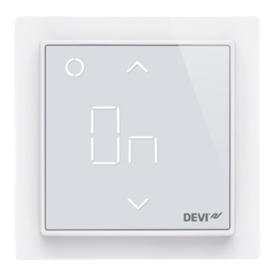
Page 13: Display Symbols
DEVIreg™ Smart Display Symbols Top part main functionalities are to support user interface through display and hold all the controller logic. Display main functionalities are to show the current status of the thermostat/switch and recognize the user actions from the buttons. Display consists of different buttons, numbers and symbols. - Page 14 DEVIreg™ Smart Nr� Type Description Button/Symbol Control button Button/Symbol Arrow Up button Button/Symbol Arrow Down button Symbol 3 digit 7 segment numbers with comma separator. “On”/”Off” text. Symbol indications Indication Mode/State Description Blue - blinking Access Point Thermostat/switch ready for Mode set-up Blue...
- Page 15 DEVIreg™ Smart Green – Active Mode Thermostat/switch waiting for blinking & Access confirmation of action Point Mode Arrows – Active Mode Safety lock is on blinking rapidly when touched Interaction directly on thermostat Function Button Description Turn thermo- 1. Touch any Thermostat/switch turn stat/switch on button...
- Page 16 DEVIreg™ Smart Frost protec- Touch and hold Deactivate frost protec- tion Control (1) for tion 1 sec. Safety lock Touch and hold Activate/Deactivate Up (2) + Down (3) safety lock for 3 sec. Factory restore Touch and hold Activates factory restore Control (1) + Up state (2) for 5 sec.
- Page 17 DEVIreg™ Smart Error Nr� Description Solu- Need restart type tion Floor Connection Contact The thermostat Sensor to sensor is service requires a restart discon- lost to operate again. nected Floor Sensor Contact The thermostat Sensor short- service requires a restart short- circuited to operate again.
- Page 18 DEVIreg™ Smart Communication Error Codes Communication Nr� Description error Wrong SSID or STA trying to connect to the AP password No IP address STA - connection acquired, no IP yet, waiting for configuration data. No internet con- STA connected and has an IP from nection DHCP server.
-
Page 19: Configuring
DEVIreg™ Smart Configuring Download App Download the DEVIsmart™ app from App Store or Google Play or at devismart.com. Find WiFi name and password for the WiFi network, that you would like to connect your thermostat/switch to. If in doubt contact net- work administrator or internet service provider. -
Page 20: Settings
DEVIreg™ Smart Settings IMPORTANT DURING THER- MOSTAT SET-UP Select whether only a floor sensor or a combination of room and floor sensor should be used. A “room only” option is also available, but requires that you have to break the small plastic seal on the back of the display module, e.g. - Page 21 DEVIreg™ Smart up to 45°. Furthermore, it will be possible to use only a room sensor. However, this option is not recommended due to an increased risk of overheating the floor. IMPORTANT: When the thermostat is used to control a floor heating element in connection with a wooden floor or similar material, always use a floor sensor and never set the maximum floor temperature to more than 35°C.
- Page 22 DEVIreg™ Smart Thermal Examples of Details Approximate resistance flooring kg/m setting for 25°C K/ W] floor temperature 0,05 8 mm HDF based > 800 28°C laminate 0,10 14 mm beech 650 – 800 31°C parquet 0,13 22 mm solid oak >...
-
Page 23: Warranty
DEVIreg™ Smart Warranty The products will, in the event of a fault that can be tracked back to a manufacturing defect in the DEVI product, be repaired or replaced free of charge. To apply for this warranty the installation must be performed by an authorized installer and the warranty certificate has to be stamped, signed and provided. -
Page 24: Radio Equipment Directive
The simplified EU declaration of conformity referred to in article 10(9) shall be provided as follows: Hereby, Danfoss A/S declares that the radio equipment type i.e. DEVIreg Smart is in compliance with Directive 2014/53/EU. The full text of the EU declaration of conformity is avail- able at the following internet address: devi�danfoss�com... -
Page 25: Disposal Instruction
DEVIreg™ Smart Disposal Instruction Installation Guide... - Page 26 DEVIreg™ Smart Installation Guide...
- Page 27 DEVIreg™ Smart Installation Guide...
- Page 28 E-mail: EH@DEVI.com www.DEVI.com Danfoss påtar seg intet ansvar for mulige feil i kataloger, brosjyrer og annet trykt materiell. Danfoss forbeholder seg rett til uten forutgående varsel å foreta endringer i sine produkter, herunder i produkter som allerede er i ordre, såfremt dette kan skje uten å...
Need help?
Do you have a question about the DEVIreg Smart and is the answer not in the manual?
Questions and answers