Table of Contents
Advertisement
Quick Links
Advertisement
Table of Contents

Subscribe to Our Youtube Channel
Related Manuals for Eaton APS3-330 Series


Summary of Contents for Eaton APS3-330 Series
- Page 1 Access Power Solutions Installation and Operation Guide (APS3-330 Series with SC300) Issue: IPN 997-00012-07A1 Issue Date: July 2018 Refer also to the separate system controller handbook. Eaton Corporation Telecommunications Power Solutions dcpower.eaton.com DCinfo@eaton.com...
- Page 2 In no event will Eaton be responsible to the purchaser or user in contract, in tort (including negligence), strict liability or otherwise for any special, indirect, incidental or consequential damage or loss whatsoever, including but not...
-
Page 3: About This Guide
Please use this email address to report any problems you find in this guide: Eaton DC Product Marketing Communications EMAIL: DCMarketingNZ@eaton.com For Further Information and Technical Assistance For further information and technical assistance see Worldwide Support on page 103. Copyright © 2007-2018 Eaton Corporation. All Rights Reserved. IPN 997-00012-07A1 July 2018... -
Page 4: Table Of Contents
Access Power Solutions Installation and Operation Guide (APS3-330 Series) Tabl e of C ontents Contents About This Guide ..........................i Scope ............................i Audience ............................. i Related Information ........................i Reporting Problems with this Guide ..................i For Further Information and Technical Assistance .............. i Table of Contents .......................... -
Page 5: Table Of Contents
System Controls ........................92 System Alarms ........................95 Digital Inputs .......................... 98 Digital Outputs (Relays) ......................98 Commissioning Completed ....................99 Equipment Incident Report ......................100 Worldwide Support ........................103 Index Copyright © 2007-2018 Eaton Corporation. All Rights Reserved. IPN 997-00012-07A1 July 2018... -
Page 7: General Description
Chapter 1 General Description Gener al D escription Overview Topic Page Access Power Solutions DC Power Systems Rectifiers System Controller Input/Output Board Other Features Copyright © 2007-2018 Eaton Corporation. All Rights Reserved. IPN 997-00012-07A1 July 2018... -
Page 8: Access Power Solutions Dc Power Systems
Access Power Solutions Installation and Operation Guide (APS3-330 Series) Access Power Solutions DC Power Systems Front View System labels DC distribution cover Rectifier modules (see details on page 4) DC common bus battery terminals ... -
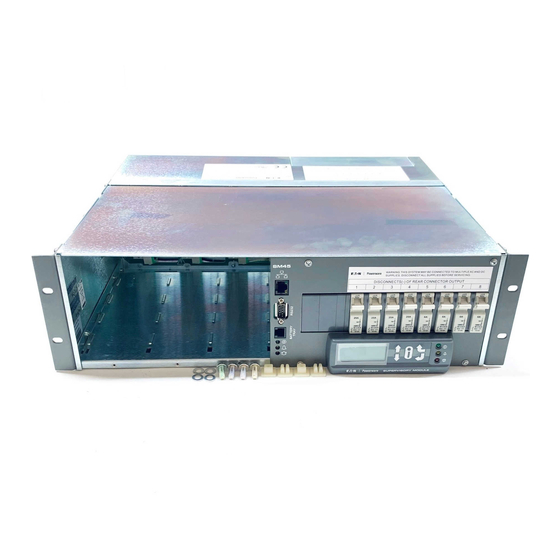
Page 9: Rear View
Load and battery cable tie rod connection details on page 22) I/O Board (see details on page 6) AC cable entry gland AC supply cord(s) may be pre-fitted. Copyright © 2007-2018 Eaton Corporation. All Rights Reserved. IPN 997-00012-07A1 July 2018... -
Page 10: Rectifiers
Access Power Solutions Installation and Operation Guide (APS3-330 Series) Rectifiers Access Power Solutions are fitted with either 48V, 2000W (APR48-ES); 48V, 1800W (APR48-3G); 48V, 900W (EPR48-3G) or 24V, 1440W (APR24-3G) rectifiers. The rectifiers are fan-cooled and hot-pluggable. See Specifications on page for further information. -
Page 11: System Controller
DCTools Configuration Software. Latest version is available free from • dcpower.eaton.com/downloads. PowerManagerII Remote Control and Monitoring Software. Contact your Eaton dc product • supplier for further information (see Worldwide Support on page 103). Recommended web browsers: Microsoft Internet Explorer 11 or later, Mozilla Firefox 3.0 or •... -
Page 12: Input / Output Board
Access Power Solutions Installation and Operation Guide (APS3-330 Series) Input / Output Board The Input / Output (I/O) board provides the I/O interfaces and connections for the SC300 system controller. The I/O board includes a range of sense inputs for dc power system control and monitoring. It also allows real time data collection from building services and other external devices, and relay outputs for alarm signals or control of external devices. - Page 13 LED (green) Power/Comms OK LED (green) 15. LVD contactor 1 connector (XH4) and status LED (green) See Troubleshooting on page for details of I/O board LED signals. Copyright © 2007-2018 Eaton Corporation. All Rights Reserved. IPN 997-00012-07A1 July 2018...
-
Page 14: Connections
Access Power Solutions Installation and Operation Guide (APS3-330 Series) Connections The following diagram shows the connections between the SC300, the I/O board, the other dc power system components and external devices, for the IOBGP-00. Other I/O board options have additional digital inputs, outputs, and an extra LVD. -
Page 15: Other Features
(on an IOBGP I/O board) Low Voltage Disconnect Option An optional Low Voltage Disconnect (LVD) is available for the Access Power Solutions (APS3-330 Series). See the diagram on page for location. This is connected as a battery disconnect. -
Page 16: Battery Time Remaining
Access Power Solutions Installation and Operation Guide (APS3-330 Series) Battery Time Remaining The SC300 obtains characterization data from every full battery discharge, to a specified end voltage. During a battery discharge, the SC300 uses this characterization data to calculate an estimated time until the battery will reach the specified end voltage. -
Page 17: Preparation
Chapter 2 Preparation Prepar ation Overview Topic Page Warnings Inspecting the Equipment and Reporting Damage Copyright © 2007-2018 Eaton Corporation. All Rights Reserved. IPN 997-00012-07A1 July 2018... -
Page 18: Warnings
Electrical Safety • Access Power Solutions (APS3-330 Series) dc power systems must be mounted in an enclosed cabinet that meets safety and fire enclosure requirements as specified in AS/NZS 60950.1 and EN 60950-1. • The dc power system may be powered from multiple ac sources. All ac sources must be isolated before internally servicing the equipment. - Page 19 Batteries • The plastic cases of batteries installed in Eaton dc power system racks must have a flammability rating of UL 94-V2 or better. • Flooded cell and VRLA lead acid batteries can emit explosive gases and must be installed with adequate ventilation.
-
Page 20: Inspecting The Equipment And Reporting Damage
Servicing. Servicing must only be performed according to specific instructions and only by personnel authorized by Eaton. This includes disassembly and/or servicing of any modules. • For further information on Servicing contact your local Eaton dc product supplier, or refer to the contact details on page 103. ... -
Page 21: Installation
Task 8 - Connect External Input/Output Cabling (if required) Task 9 - Connect Additional Input/Output (if required - SC300 only) Task 10 - Connect to the AC Supply Point Installation Completed Copyright © 2007-2018 Eaton Corporation. All Rights Reserved. IPN 997-00012-07A1 July 2018... -
Page 22: Installation Tasks
Access Power Solutions Installation and Operation Guide (APS3-330 Series) Installation Tasks Before starting the installation, review the following information: Required Equipment and Tools on page • Warnings and Cautions on page • Inspecting the Equipment and Reporting Damage on page •... - Page 23 If necessary, install higher rated RCD(s). The maximum earth leakage current of Access Power Rectifiers is given in the Specifications on page 71. Copyright © 2007-2018 Eaton Corporation. All Rights Reserved. IPN 997-00012-07A1 July 2018...
- Page 24 If necessary, replace the upstream ac supply-disconnect device to achieve adequate discrimination. Or, contact your Eaton dc product supplier for advice (see Worldwide Support on page 103). Copyright © 2007-2018 Eaton Corporation. All Rights Reserved.
-
Page 25: Task 2 - Prepare Aps
If the polarity of the APS is not correct for the equipment to be powered then contact your Eaton dc product supplier for advice (see Worldwide Support on page 103). Step 3 - Check position of mounting brackets APSs are pre-assembled with 19-inch rack-mounting brackets as shown in the following diagram. - Page 26 The current rating of the MCBs must be derated to 75%. The APS can use Chint or Eaton circuit breakers. However, Chint and Eaton circuit breakers are not interchangeable. When replacing existing circuit breakers or fitting new ones, use the type that is already in use (see Spare Parts on page for ordering details).
- Page 27 The current rating of the MCBs must be derated to 75%. The APS can use either Chint or Eaton circuit breakers. However, Chint and Eaton circuit breakers are not interchangeable. When replacing existing circuit breakers or fitting new ones, use the type that is already in use (see Spare Parts on page ordering details).
-
Page 28: Task 3 - Connect The Ac Supply Cable
Access Power Solutions Installation and Operation Guide (APS3-330 Series) Busbar chassis screw Busbar Busbar stand-off screw Stand-off DC common bar Procedure complete Task 3 - Connect the AC Supply Cable If the APS has pre-fitted ac cord(s) then ignore this task. - Page 29 Ensure the ferrule of the crimp lug covers all strands of wire. Connect the earth conductor to the earth termination point next to the ac terminals (see the diagram on page 3). Copyright © 2007-2018 Eaton Corporation. All Rights Reserved. IPN 997-00012-07A1 July 2018...
- Page 30 Access Power Solutions Installation and Operation Guide (APS3-330 Series) Step 6 - Terminate the phase and neutral (if used) conductor(s) at APS If ac MCB(s) fitted then connect the phase conductor(s) to the MCB(s). Ensure the insulating card covers the MCB terminal(s).
-
Page 31: Task 4 - Mount The Aps In The Rack
Recommended for access to cable terminations. Step 2 - Fit cage nuts Fit cage nuts in the correct positions to match the screw holes in the APS rack mounting brackets. Copyright © 2007-2018 Eaton Corporation. All Rights Reserved. IPN 997-00012-07A1 July 2018... -
Page 32: Task 5 - Connect The Dc Load And Battery Cables
Access Power Solutions Installation and Operation Guide (APS3-330 Series) Step 3 - Mount the APS Carefully feed the ac supply cable or cord(s) into the rack. Lift the APS to the correct position in the rack. A suitable mechanical support or a second person must support the weight of the APS. - Page 33 Secure the cables with cable ties to the cable tie rod to ensure there will be no strain on the terminals. Test the insulation resistance of the cables. Procedure complete Copyright © 2007-2018 Eaton Corporation. All Rights Reserved. IPN 997-00012-07A1 July 2018...
-
Page 34: Task 6 - Install The Batteries
The Mid-point Monitoring sense wires must have short-circuit protection fitted close to the battery terminals. Use the Battery Mid-point Monitoring kits from Eaton (see Spare Parts on page 68) or equivalent. Connect a Mid-point Monitoring sense wire to the middle interconnecting link on each string of batteries (see following diagram). -
Page 35: Task 7 - Mount The Battery Temperature Sensor
Do not attach the sensor to a battery case, battery cables, terminals or • interconnecting bars. Do not expose the sensor to direct sunlight, or air movements from • air-conditioning systems or open windows. Procedure complete Copyright © 2007-2018 Eaton Corporation. All Rights Reserved. IPN 997-00012-07A1 July 2018... -
Page 36: Task 8 - Connect External Input/Output Cabling (If Required)
Access Power Solutions Installation and Operation Guide (APS3-330 Series) Task 8 - Connect External Input/Output Cabling (if required) Refer to Input/Output Board on page for details of how the I/O board can control and monitor external devices. If no external devices are to be connected then ignore this task. -
Page 37: Task 9 - Connect Additional Input/Output (If Required)
Connect the SiteSure-3G cable to a spare RJ45 socket (S1, S2 or S3) on the Voltage Feed Module board. See the diagram on page for socket location. Copyright © 2007-2018 Eaton Corporation. All Rights Reserved. IPN 997-00012-07A1 July 2018... -
Page 38: Task 10 - Connect To The Ac Supply Point
Access Power Solutions Installation and Operation Guide (APS3-330 Series) Task 10 - Connect to the AC Supply Point • A suitably qualified electrician familiar with local wiring regulations must carry out the ac connection. Step 1 - Replace all covers on the APS Step 2 - Connect at the ac supply point Check the ac supply point is isolated. -
Page 39: Start-Up
Task 2 - Pre-Power-Up Checklist Task 3 - Applying AC Power Task 4 - Configuring the DC Power System Task 5 - Applying DC Power to Battery and Load Start-Up Completed Copyright © 2007-2018 Eaton Corporation. All Rights Reserved. IPN 997-00012-07A1 July 2018... -
Page 40: Start-Up Tasks
Access Power Solutions Installation and Operation Guide (APS3-330 Series) Start-Up Tasks Complete all the Installation tasks (see details on page 16) before starting these Start-Up tasks. Complete the Start-Up tasks in the following order: Task Description Reference Insert the Rectifiers... -
Page 41: Task 2 - Pre-Power-Up Checklist
The SC300 system controller will turn on (green Power On LED is on) when the rectifiers • start. During start-up of the system controller the rectifier yellow alarm LEDs will flash until • the rectifiers are registered. Copyright © 2007-2018 Eaton Corporation. All Rights Reserved. IPN 997-00012-07A1 July 2018... -
Page 42: Task 4 - Configuring The Dc Power System
Access Power Solutions Installation and Operation Guide (APS3-330 Series) After start-up of the system controller: Press any key on the system controller to silence the alarm. • Depending on the configuration file settings, one or both alarm LED(s) may be on and the system controller may display some system alarm messages. -
Page 43: Task 5 - Applying Dc Power To Battery And Load
Check the rectifier currents. Verify the load current is as expected for the load and battery size and does not exceed the maximum load rating (see details on page 71). Copyright © 2007-2018 Eaton Corporation. All Rights Reserved. IPN 997-00012-07A1 July 2018... -
Page 44: Start-Up Completed
Access Power Solutions Installation and Operation Guide (APS3-330 Series) Step 5 - Charge the batteries Charge the batteries according to the battery manufacturer’s recommendations. If an Equalize charge is recommended by the battery manufacturer then follow the instructions. Equalize increases the system voltage to the Equalize voltage for the Equalize duration. -
Page 45: System Controller
Chapter 5 System Controller System C ontroller Topic Page Configuration File Starting the SC300 SC300 Operation using the Keypad and Screen SC300 Operation Using a PC/Laptop SC300 Identity Information Copyright © 2007-2018 Eaton Corporation. All Rights Reserved. IPN 997-00012-07A1 July 2018... -
Page 46: Configuration File
Access Power Solutions Installation and Operation Guide (APS3-330 Series) Configuration File The operational settings of the dc power system are stored in a configuration file loaded into the SC300 system controller. The SC300 is supplied pre-loaded with a configuration file. If this configuration file has been customized for the site then no further configuration changes will be necessary. -
Page 47: Starting The Sc300
Soft key 1 label Soft key 1 Navigation keys (Up - Down - Left - Right) Soft key 2 Soft key 2 label Copyright © 2007-2018 Eaton Corporation. All Rights Reserved. IPN 997-00012-07A1 July 2018... -
Page 48: Keypad Access Security
Keypad access is Read Only, or PIN Protected and the keypad access PIN is lost. The SC300 will continue to function, but no configuration changes can be made. Contact your Eaton dc product supplier or Eaton for advice (see Worldwide Support on page 103). -
Page 49: Sc300 Operation Using A Pc/Laptop
When Disabled, the audible indicator will still indicate an invalid key press. SC300 Operation Using a PC/Laptop DCTools is configuration software for editing a system controller's configuration file (on-line) and monitoring the operation of Eaton's dc power systems. It is available free from dcpower.eaton.com/downloads. Using DCTools via USB DCTools can be run on a PC/laptop connected to the SC300's USB port. -
Page 50: Sc300 Identity Information
Access Power Solutions Installation and Operation Guide (APS3-330 Series) SC300 Identity Information The following identity information is stored in the SC300. Parameter Description Where to find: Serial Number The SC300 serial number (factory set). SC300: Info Web: Software Version The version of the embedded software Identity >... - Page 51 A name that can be entered for the Name configuration file. This name is automatically loaded if the user selects a Generic System Type, or when a configuration file is loaded from web or DCTools. Copyright © 2007-2018 Eaton Corporation. All Rights Reserved. IPN 997-00012-07A1 July 2018...
- Page 52 Access Power Solutions Installation and Operation Guide (APS3-330 Series) The following configuration information is automatically stored by the SC300: Parameter Description Where to find: Master The name of the configuration file that Configuration was last loaded into the SC300 by web interface or DCTools.
-
Page 53: Generic System Types
Set for 1 LVD only. EPS 48V LVD Loads a standard 48V positive earth settings. Includes an LVD. EPS48V Loads a standard 48V positive earth settings. No LVD. Copyright © 2007-2018 Eaton Corporation. All Rights Reserved. IPN 997-00012-07A1 July 2018... - Page 54 Access Power Solutions Installation and Operation Guide (APS3-330 Series) Configuration item: Parameter Description Where to find: Generic System If a suitable configuration file is not Type available, select the appropriate Web: Identity > Software system type here. This will load DCTools: suitable settings into the SC300.
-
Page 55: Maintenance
Eaton. This includes disassembly and/or servicing of any modules. • For further information on Servicing contact your local Eaton dc product supplier, or refer to the contact details on page 103. Topic Page... -
Page 56: Troubleshooting
Access Power Solutions Installation and Operation Guide (APS3-330 Series) Troubleshooting Use the table to troubleshoot minor installation and operational problems. For additional assistance see contact details on page 103. Return items for replacement or repair with a completed Equipment Incident Report on page 100. - Page 57 Install additional rectifiers. and rectifier yellow LEDs are capacity. on (rectifiers are in current Battery is recharging after ac Check battery has recharged within limit). supply failure. expected time. Copyright © 2007-2018 Eaton Corporation. All Rights Reserved. IPN 997-00012-07A1 July 2018...
- Page 58 Access Power Solutions Installation and Operation Guide (APS3-330 Series) Problem Possible Cause Required Action High system output voltage. Temperature Compensation is None. This is normal operation (if active and the battery batteries are connected). Disable temperature is below the Temperature Compensation if no reference temperature.
-
Page 59: System Controller Problems
Incorrectly configured shunt Check shunt mapping and gain is correct. inputs. Current is within the Battery None, normal operation. State Threshold. See details in the System Controller Operation Handbook. Copyright © 2007-2018 Eaton Corporation. All Rights Reserved. IPN 997-00012-07A1 July 2018... - Page 60 Access Power Solutions Installation and Operation Guide (APS3-330 Series) Problem Possible Cause Required Action SC300 or DCTools/Web Failed, disconnected or Replace, connect or configure sensor. displays ??? or N/A unconfigured sensor. Faulty or disconnected voltage Replace or connect voltage feed module.
- Page 61 Check S3P Access is enabled. See details in are disabled. the System Controller Operation Handbook. Password required to change See Write Access Password in the System settings (using DCTools or Controller Operation Handbook. PowerManagerII). Copyright © 2007-2018 Eaton Corporation. All Rights Reserved. IPN 997-00012-07A1 July 2018...
- Page 62 Access Power Solutions Installation and Operation Guide (APS3-330 Series) Problem Possible Cause Required Action Web communications Ethernet communications See previous entry. problem problem. Cannot connect to web server. Check IP address and other settings in SC300 are correct. Check correct IP address is used in web browser address bar.
- Page 63 I/O board. See details in the System Controller Operation Handbook . Contactor is disconnected. Check the control and dc power cables are connected. See details on page 8. Copyright © 2007-2018 Eaton Corporation. All Rights Reserved. IPN 997-00012-07A1 July 2018...
-
Page 64: Replacing Or Adding A Rectifier
Access Power Solutions Installation and Operation Guide (APS3-330 Series) Replacing or Adding a Rectifier Rectifiers can be replaced without switching off the dc power system and disconnecting the equipment it powers. • To reduce the risk of electric shock and maintain optimum system cooling, always cover ... -
Page 65: Replacing Or Adding A Load Mcb
Disconnect the load cable and the fuse fail detect wire from the MCB top terminal. Insulate the ends of both the cable and the wire. Undo the bottom MCB terminal. Unclip the MCB from the DIN rail and remove the MCB. Copyright © 2007-2018 Eaton Corporation. All Rights Reserved. IPN 997-00012-07A1 July 2018... -
Page 66: Replacing The System Controller
• contact your Eaton dc power system supplier to obtain a master configuration file to suit • the dc power system. This file will have to be customized for the site. - Page 67 See Backup and Restore on page in the System Controller Operation Handbook. If you receive an error message about the MIB file version, please contact your Eaton dc product supplier for advice, or use a web connection for the backup/restore operation.
- Page 68 Access Power Solutions Installation and Operation Guide (APS3-330 Series) Step 5 - Check the system controller operation If there is only one IO Board in the system, this IO Board will be automatically mapped as IOB 1. If more than one IO Board is present, follow the procedure below: Map the I/O board : In DCTools/Web go to: RXP.
-
Page 69: Replacing The Input/Output Board
Label then disconnect all the input/output wires connected to the push-connect terminals (XH15 - XH21). Place the board in an anti-static bag and return for service. See Equipment Incident Report on page 100. Copyright © 2007-2018 Eaton Corporation. All Rights Reserved. IPN 997-00012-07A1 July 2018... - Page 70 Access Power Solutions Installation and Operation Guide (APS3-330 Series) Step 4 - Fit the new I/O board Reconnect all the input/output wires to the push-connect terminals (XH15 - XH21). Fit the I/O board on to the support posts in the APS.
-
Page 71: Battery Mid-Point / Quarter-Point Monitoring (String Fail) Alarm
Please remember that the owner is responsible and liable to ensure those EPA guidelines or equivalent local regulations are followed. For assistance contact your local hazardous waste facility or Worldwide Support on page 103. Copyright © 2007-2018 Eaton Corporation. All Rights Reserved. IPN 997-00012-07A1 July 2018... -
Page 73: Equipment And Tools
Test load (to suit maximum output of dc power system) • Labelling tool and labels • Clamp-on ammeter • USB micro cable • RJ-45 (Ethernet) patch cables as needed • Copyright © 2007-2018 Eaton Corporation. All Rights Reserved. IPN 997-00012-07A1 July 2018... -
Page 74: Spare Parts
Access Power Solutions Installation and Operation Guide (APS3-330 Series) Spare Parts Item Description Part Number Rectifier. 48V, 2000W: Eaton APR48-ES See replacement procedure on page 58. 48V, 1800W: Eaton APR48-3G 48V, 900W: Eaton EPR48-3G 24V, 1440W: Eaton APR24-3G Rectifier blank panel... - Page 75 When a bolt and nut is torqued use a spanner to prevent rotation. Use hand tools when loosening and tightening stainless steel fasteners. Lubricate bolts before tightening to prevent them locking up. Copyright © 2007-2018 Eaton Corporation. All Rights Reserved. IPN 997-00012-07A1 July 2018...
-
Page 77: Specifications
APR48-3G rectifiers: 5.4kW* APR48-ES rectifiers: 6.0kW* Load Current (maximum) 133A Output Voltage Range 21.5 - 32V / 43 - 57.5V * subject to the maximum load current as specified Copyright © 2007-2018 Eaton Corporation. All Rights Reserved. IPN 997-00012-07A1 July 2018... - Page 78 Access Power Solutions Installation and Operation Guide (APS3-330 Series) Rectifiers Operating Ranges APR24-3G/APR48-3G/EPR48-3G: Rated: 175 – 275V Full output up to 50°C [122°F] Extended: 90 – 300V Reduced output power below 175V APR48-ES: Rated: 185 – 275V Full output up to 50°C [122°F] Extended: 90 –...
- Page 79 24 (with additional IOBGP-01 I/O boards) Range –35V to +35V Resolution <30mV Accuracy ±0.5% at 25°C [77°F], ±1% over rated temperature range Maximum Cable Length 20m (65 feet) Copyright © 2007-2018 Eaton Corporation. All Rights Reserved. IPN 997-00012-07A1 July 2018...
- Page 80 Access Power Solutions Installation and Operation Guide (APS3-330 Series) Low Voltage Disconnect (IOBGP) Number of contactor connections 2 or 3 per IOBGP I/O board Number of LVD channels Contactor Type Normally open Latched (IOBGP-10/11/20/21 only) Contactor Coil Voltage (nominal) 12V, 24V or 48V Maximum Hold-in Current 1.2A (per contactor)
-
Page 81: Cable Ratings
Chint, DZ158-125 Series, 100A, Curve 35mm / 1AWG 307-912519-61 Chint, DZ158-125 Series, 125A, Curve 50mm / 0AWG * or local equivalent. Please contact your local Eaton sales office. Copyright © 2007-2018 Eaton Corporation. All Rights Reserved. IPN 997-00012-07A1 July 2018... -
Page 83: Controller Menus
At each menu screen press Enter to access the associated configuration menu screen(s). These menus have multiple configuration menu screens. See details in the System Controller Operation Handbook. Copyright © 2007-2018 Eaton Corporation. All Rights Reserved. IPN 997-00012-07A1 July 2018... -
Page 84: Connector Pin-Outs
Access Power Solutions Installation and Operation Guide (APS3-330 Series) Connector Pi n-outs System Controller Connector Pin-outs Connector Type Purpose Description DB9M RS-232 / RS485 Serial Interface RD (Receive Data) TD (Transmit Data) DTR (Data Terminal Ready) Common (Ground) RTS (Request to Send) -
Page 85: I/O Board (Iobgp-00, -01, 10, 11, 20, 21) Connector Pin-Outs
+12V out Current Input 2 Common Current Input 2 0V out Current Input 3 Common Current Input 3 RJ45 Temperature Sense Inputs Sensor signal is referenced to live bus. Copyright © 2007-2018 Eaton Corporation. All Rights Reserved. IPN 997-00012-07A1 July 2018... - Page 86 Access Power Solutions Installation and Operation Guide (APS3-330 Series) Connector Type Purpose Description Temp Sense 1+ Temp Sense 1- Temp Sense 2+ Temp Sense 2- LVD Power Bus live Bus common Bus Voltage Sense Input Controller reference (Bus live) Controller sense (Bus common)
- Page 87 Digital input signals are referenced to live bus. +12V out AC Distribution Fan Fail AC Distribution MOV Fail 0V out (system live - protected) System common - protected Copyright © 2007-2018 Eaton Corporation. All Rights Reserved. IPN 997-00012-07A1 July 2018...
- Page 88 Access Power Solutions Installation and Operation Guide (APS3-330 Series) Connector Type Purpose Description YH11/ RJ45 RXP System System Positive 24/48V YH11A Communications System Positive 24/48V (IOBGP-10/11 /20/21 only) RS485-A RS485-B System Negative 24/48V RJ45 connector pin-outs RJ45 plug pin-outs Copyright © 2007-2018 Eaton Corporation. All Rights Reserved.
-
Page 89: Transient Protection
Transient Protection Transi ent Protecti on To prevent damage to Eaton Access Power Solutions from lightning and transient over-voltages, structural lightning protection and transient protection must be installed at each site. Transient protection will also protect against other sources of transients, such as: Circuit or grid switching by the power company •... - Page 90 Access Power Solutions Installation and Operation Guide (APS3-330 Series) Primary Transient Protection Primary transient protection must be considered at all sites. Eaton recommends primary transient protection on the incoming ac supply either at the main ac switchboard or sub-switchboard. In the absence of sufficient information, primary transient protective devices with a minimum repeat strike rating of 100kA (8/20μs wave shape) are recommended.
- Page 91 2kA. Tertiary Transient Protection Eaton rectifiers are fitted with 6kV/3kA transient protection. This is designed to protect the rectifiers from voltage spikes generated during operation of the upstream transient protection system. Do not install rectifiers without adequate upstream surge protection.
-
Page 93: Earth Bonding
21). This link prevents these very large voltages from developing and protects the rectifiers from surge related damage. If your installation uses a mesh earth, then Eaton recommends that this factory fitted ac-dc earth link is retained. No further action is required. - Page 94 Access Power Solutions Installation and Operation Guide (APS3-330 Series) Step 2 - Remove or replace the ac-dc Earth Link Ignore this Step if the factory fitted ac-dc earth link is used. There are two options if the ac-dc earth link cannot be retained. Either: •...
-
Page 95: Commissioning
See details on page System Controls See details on page System Alarms See details on page Digital Inputs See details on page Digital Outputs (Relays) See details on page Copyright © 2007-2018 Eaton Corporation. All Rights Reserved. IPN 997-00012-07A1 July 2018... -
Page 96: Analog Inputs
Access Power Solutions Installation and Operation Guide (APS3-330 Series) Analog Inputs Equipment required: Digital Voltmeter • DC Load bank • DC Current Clamp meter • Trim pot adjustment tool • Thermometer • Test Test procedure Adjustment • Measure the dc voltage across the dc bus. - Page 97 As the analog inputs can be configured for many different types of analog signal, tests have not been detailed on this test sheet. User assigned analog inputs are not available on all systems. Copyright © 2007-2018 Eaton Corporation. All Rights Reserved. IPN 997-00012-07A1 July 2018...
-
Page 98: System Controls
Access Power Solutions Installation and Operation Guide (APS3-330 Series) System Controls Equipment Required: DC Load bank • Test Test procedure Adjustment • Apply a load to the power system. Voltage Control None • With DCTools, ensure the bus voltage matches the Target... - Page 99 Increase the LVD Disconnect Voltage Threshold. Automatic • Reduce the system voltage below the LVD Disconnect Operation Voltage Threshold. Note 7 • Wait for the configured Recognition Period. • Ensure the LVD disconnects. Copyright © 2007-2018 Eaton Corporation. All Rights Reserved. IPN 997-00012-07A1 July 2018...
- Page 100 Access Power Solutions Installation and Operation Guide (APS3-330 Series) Test Test procedure Adjustment • Ensure the SC300 displays an LVD Disconnected alarm • Ensure the I/O board LVD LED is off. • Increase the system voltage above the configured Reconnect Voltage.
-
Page 101: System Alarms
Turn off the ac MCBs to 2 rectifiers (if fitted). Multiple rectifier fail • The rectifiers will turn off. • Ensure alarm operates. • Remove a rectifier from the system. Rectifier comms lost • Ensure alarm operates. Copyright © 2007-2018 Eaton Corporation. All Rights Reserved. IPN 997-00012-07A1 July 2018... - Page 102 Access Power Solutions Installation and Operation Guide (APS3-330 Series) Test Test procedure Adjustment • Remove 2 rectifiers from the system. Multiple Rectifier comms lost • Ensure alarm operates. • Turn off the ac to more than 20% of the rectifiers in the Partial AC Fail system.
- Page 103 Change the AC Frequency Threshold. Note 6 • Ensure alarm operates. • Change the state of the digital input with Engine Run Engine Run Option function. Note 7 • Ensure alarm operates. Copyright © 2007-2018 Eaton Corporation. All Rights Reserved. IPN 997-00012-07A1 July 2018...
-
Page 104: Digital Inputs
Access Power Solutions Installation and Operation Guide (APS3-330 Series) Notes Ensure Alarm Tracking is disabled. Ensure Temperature Compensation is enabled. If the load is not connected to the load MCBs and if an electronic Fuse Fail detect circuits is installed, this test can also be performed as follows: Turn off the load MCB •... -
Page 105: Commissioning Completed
Commissioning Completed Restore the original (backed-up prior to the testing) configuration file. Use DCTools/Web to change any configuration file settings that were noted as incorrect during the Commissioning tests. Copyright © 2007-2018 Eaton Corporation. All Rights Reserved. IPN 997-00012-07A1 July 2018... -
Page 106: Equipment Incident Report
Please enter as much information as you can. Send the completed form, together with the item for repair to your nearest authorized service agent. NOTE: Only one fault to be recorded per form. For further information contact your local Eaton dc product supplier or Eaton (see contact details on page 103). Or email: CustomerServiceNZ@eaton.com... - Page 107 ______________________________________________________________________________________ ______________________________________________________________________________________ ______________________________________________________________________________________ ______________________________________________________________________________________ ______________________________________________________________________________________ ______________________________________________________________________________________ ______________________________________________________________________________________ ______________________________________________________________________________________ ______________________________________________________________________________________ ______________________________________________________________________________________ ______________________________________________________________________________________ ______________________________________________________________________________________ ______________________________________________________________________________________ ______________________________________________________________________________________ ______________________________________________________________________________________ ______________________________________________________________________________________ ______________________________________________________________________________________ ______________________________________________________________________________________ ______________________________________________________________________________________ ______________________________________________________________________________________ ______________________________________________________________________________________ ______________________________________________________________________________________ ______________________________________________________________________________________ ______________________________________________________________________________________ ______________________________________________________________________________________ ______________________________________________________________________________________ SG/03 ISS06 Copyright © 2007-2018 Eaton Corporation. All Rights Reserved. IPN 997-00012-07A1 July 2018...
-
Page 109: Worldwide Support
Worldwide Support Worldwide Support For product information and a complete listing of worldwide sales offices, visit Eaton's website at: dcpower.eaton.com or email: DCinfo@eaton.com For technical support contact either your local Eaton dc product representative, the closest office from the following list, telephone (+64) 3-343-7448, or email CustomerServiceNZ@eaton.com... -
Page 111: Index
Write Access Password • 55 Configuration File • 36, 40, 60 Battery Backup and Restore • 40 Battery Charging • 37 Connection to AC Supply • 22, 32, 35 Copyright © 2007-2018 Eaton Corporation. All Rights Reserved. IPN 997-00012-07A1 July 2018... - Page 112 Access Power Solutions Installation and Operation Guide (APS3-330 Series) Current Battery Current • 53 High AC Voltage Protection • 16 Load Current • 53 Rectifier Current • 41 Current Sense • 6, 8, 73 Identity Information • 44 Input/Output (I/O) Board Connections to other system components •...
- Page 113 Earth Leakage Current • 16, 71 Configuration File • 60 Inserting the Rectifiers • 34 Connector Pin-outs • 78 Location • 2 Internal Clock • 56 Output Voltage and Current • 71 Copyright © 2007-2018 Eaton Corporation. All Rights Reserved. IPN 997-00012-07A1 July 2018...
- Page 114 Access Power Solutions Installation and Operation Guide (APS3-330 Series) Keypad • 53 Technical Assistance • 103 LEDs (SC300) • 53 Main Screen • 41 N/A (in DCTools/Web) • 54 00 Alarms • 42 Connector • 5, 8 SC300 Alarms • 53 USB Cable •...
Need help?
Do you have a question about the APS3-330 Series and is the answer not in the manual?
Questions and answers