Table of Contents
Advertisement
Quick Links
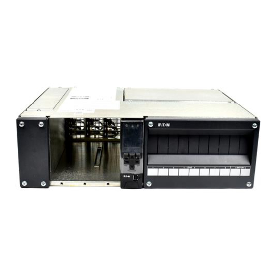
Eaton APS3-421-A0A
DC Power System
A l l t r a d e m a r k s , b r a n d n a m e s , a n d b r a n d s a p p e a r i n g h e r e i n a r e t h e p r o p e r t y o f t h e i r r e s p e c t i v e o w n e r s .
• C r i t i c a l a n d e x p e d i t e d s e r v i c e s
• I n s t o c k / R e a d y - t o - s h i p
Artisan Scientific Corporation dba Artisan Technology Group is not an affiliate, representative, or authorized distributor for any manufacturer listed herein.
In Stock
New From Surplus Stock
Open Web Page
https://www.artisantg.com/88291-1
• We b u y y o u r e x c e s s , u n d e r u t i l i z e d , a n d i d l e e q u i p me n t
• F u l l - s e r v i c e , i n d e p e n d e n t r e p a i r c e n t e r
Advertisement
Table of Contents

Related Manuals for Eaton APS3-421-A0A


Summary of Contents for Eaton APS3-421-A0A
- Page 1 Eaton APS3-421-A0A DC Power System In Stock New From Surplus Stock Open Web Page https://www.artisantg.com/88291-1 A l l t r a d e m a r k s , b r a n d n a m e s , a n d b r a n d s a p p e a r i n g h e r e i n a r e t h e p r o p e r t y o f t h e i r r e s p e c t i v e o w n e r s .
- Page 2 Installation and Operation Guide (APS3-400 Series) Issue: IPN 997-00012-52D Issue Date: July 2010 Refer to the separate SC200 or SC100 system controller handbook for full details of the system controller operation - www.powerquality.eaton.com/DC-Manuals. Eaton Corporation Telecommunications Power Solutions www.eaton.com/telecompower DCinfo@eaton.com...
- Page 3 The information contained in this literature is subject to change without notice. Subject to the right to use its equipment, Eaton Corporation does not convey any right, title or interest in its intellectual property, including, without limitation, its patents, copyrights and know-how.
-
Page 4: About This Guide
Please use this email address to report any problems you find in this guide: Eaton DC Product Marketing Communications EMAIL: DCMarketingNZ@eaton.com For Further Information and Technical Assistance For further information and technical assistance see Worldwide Support on page 103. Copyright © 2007-2010 Eaton Corporation. All Rights Reserved. IPN 997-00012-52D July 2010... - Page 5 Access Power Solutions Installation Guide (APS3-400 Series) Copyright © 2007-2010 Eaton Corporation. All Rights Reserved. IPN 997-00012-52D July 2010...
-
Page 6: Table Of Contents
Task 3 - Applying AC Power....................35 Task 4 - Configuring the DC Power System ............... 36 Task 5 - Applying DC Power to Battery and Load ............37 Start-Up Completed ....................... 38 Copyright © 2007-2010 Eaton Corporation. All Rights Reserved. IPN 997-00012-52D July 2010... - Page 7 Commissioning Analog Inputs ..........................86 System Controls ........................88 System Alarms.........................92 Digital Inputs...........................95 Digital Outputs (Relays) ......................96 Commissioning Completed ....................96 Appendix G Circuit Diagrams Equipment Incident Report Worldwide Support Index Copyright © 2007-2010 Eaton Corporation. All Rights Reserved. IPN 997-00012-52D July 2010...
-
Page 8: Overview
Chapter 1 General Description General Description Overview Topic Page Access Power Solutions DC Power Systems Model Numbers Rectifiers System Controller Other Features Copyright © 2007-2010 Eaton Corporation. All Rights Reserved. IPN 997-00012-52D July 2010... -
Page 9: Access Power Solutions Dc Power Systems
5) DC Distribution with up to 8 Load and 2 Battery Circuit Breakers. Load breakers alarm on overload only, battery breakers alarm on overload or when switched off. Copyright © 2007-2010 Eaton Corporation. All Rights Reserved. IPN 997-00012-52D July 2010... -
Page 10: Rear View
IEC plugs (see inset). Load and Battery live cable terminals Load and battery cable entries DC terminal cover Input/Output (I/O) cover Copyright © 2007-2010 Eaton Corporation. All Rights Reserved. IPN 997-00012-52D July 2010... -
Page 11: Model Numbers
Left: APR48-3G Right: APR48-ES Power On LED (Green) Minor Alarm LED (Yellow) Major Alarm LED (Red) Serial Number Retaining Screw. Tighten to 1.5Nm (13.3 inch-pounds). Copyright © 2007-2010 Eaton Corporation. All Rights Reserved. IPN 997-00012-52D July 2010... -
Page 12: System Controller
The SC100 system controller is a full-featured control and monitoring solution which provides alarm notifications via dial-out modem to PowerManagerII remote monitoring software, SMS text messaging, or by relay contact closures. Copyright © 2007-2010 Eaton Corporation. All Rights Reserved. IPN 997-00012-52D July 2010... -
Page 13: Compatible Software
DCTools Configuration Software. Latest version is available free from • www.powerquality.eaton.com/downloads. PowerManagerII Remote Control and Monitoring Software. Contact your Eaton dc product • supplier for further information (see Worldwide Support on page 103). Recommended web browsers (SC200 only): Microsoft Internet Explorer 8 (IE6 is compatible •... -
Page 14: Other Features
To ensure reliable operation Mid-point Monitoring operates only when the battery is in float charge and after a configurable lockout period since the last battery discharge, Fast Charge, Equalize or Battery Test. Copyright © 2007-2010 Eaton Corporation. All Rights Reserved. IPN 997-00012-52D July 2010... -
Page 15: Battery Time Remaining
The estimated charge left in the battery (Ah). Charge (SOC) For details refer to Battery Time Remaining in the SC200 or SC100 System Controller Operation Handbook (see Related Information on page i). Copyright © 2007-2010 Eaton Corporation. All Rights Reserved. IPN 997-00012-52D July 2010... -
Page 16: Chapter 2 Preparation
Chapter 2 Preparation Preparation Overview Topic Page Warnings Inspecting the Equipment and Reporting Damage Copyright © 2007-2010 Eaton Corporation. All Rights Reserved. IPN 997-00012-52D July 2010... -
Page 17: Warnings
Rectifiers and batteries contain hazardous energy levels. Only personnel trained and experienced in dc power systems are to service/maintain this equipment. • Always use insulated tools. • Do not short-circuit the live and common bus bars or cables. Copyright © 2007-2010 Eaton Corporation. All Rights Reserved. IPN 997-00012-52D July 2010... - Page 18 The short circuit current capability of the battery circuit connected to the battery input terminals must not exceed 5,000A. • The plastic cases of batteries installed in Eaton dc power system racks must have a flammability rating of UL 94-V2 or better. •...
-
Page 19: Inspecting The Equipment And Reporting Damage
EMC Compliance • This Eaton product ("the equipment") has been tested and found to comply with the limits for a Class B digital device, pursuant to part 15 of the Federal Communications Commission (FCC) Rules. These limits are designed to provide reasonable protection against harmful interference in a residential installation. -
Page 20: Installation
Task 6 - Install the Batteries Task 7 - Mount the Battery Temperature Sensor Task 8 - Connect the AC Supply Cable Task 9 - Connect to the AC Supply Point Installation Completed Copyright © 2007-2010 Eaton Corporation. All Rights Reserved. IPN 997-00012-52D July 2010... -
Page 21: Installation Tasks
Connect the High VAC alarm output to one of the Digital Inputs on the I/O Interface Board (see the diagram on page for location). The High VAC alarm signal lines must be isolated from the ac supply by a voltage-free relay contact. Copyright © 2007-2010 Eaton Corporation. All Rights Reserved. IPN 997-00012-52D July 2010... - Page 22 In all cases, the external circuit breaker(s) must be two-pole type wired in each conductor, if: • the ac supply is 2W (see Specifications on page 71), or • the ac supply is 1W+N but the neutral is not clearly identified. Copyright © 2007-2010 Eaton Corporation. All Rights Reserved. IPN 997-00012-52D July 2010...
- Page 23 If the curve of an upstream ac supply-disconnect device crosses the curve for the rectifier fuse there may not be adequate discrimination. Contact your Eaton dc product supplier for advice (see Worldwide Support on page 103).
-
Page 24: Task 2 - Customize Aps
See the following table for part numbers. Fit circuit breaker blank panels to cover any unused positions. Replace the dc circuit breaker cover. Switch all circuit breakers to the OFF ("0") position. Copyright © 2007-2010 Eaton Corporation. All Rights Reserved. IPN 997-00012-52D July 2010... -
Page 25: Item Description
80A, 80V dc (derates to 48A with Heinemann AMA1R-B2-AI-20-D-DU-52-80-1 adjacent space*) 100A, 80V dc (derates to 60A with Heinemann AMA1R-B2-AI-20-D-DU-52-100-1 adjacent space*) * Circuit breaker must have adjacent space. Refer to the installation instructions. Copyright © 2007-2010 Eaton Corporation. All Rights Reserved. IPN 997-00012-52D July 2010... -
Page 26: Task 3 - Mount The Aps In The Rack
Front: 24" (600mm) Rear: If top access is unrestricted: 4” (100mm) If top access is restricted: 24" (600mm) Top: 3" (75mm) minimum from other equipment in the rack. Copyright © 2007-2010 Eaton Corporation. All Rights Reserved. IPN 997-00012-52D July 2010... - Page 27 (bonded) to the ac ground, via the chassis (Step 4B). The APS is supplied with the dc common bar bonded to the chassis via a link on the dc common bar. Copyright © 2007-2010 Eaton Corporation. All Rights Reserved. IPN 997-00012-52D July 2010...
- Page 28 Terminate the cable at the site's telecom ground electrode directly or via the site's telecom ground bus bar, if provided. Remove link between dc common bar and Telecom ground link cable to site's telecom chassis. ground electrode (1 AWG) Copyright © 2007-2010 Eaton Corporation. All Rights Reserved. IPN 997-00012-52D July 2010...
- Page 29 A Service Person shall check whether or not the socket-outlets from which the APS is to be powered provide a connection to the building protective earth. If this connection is provided, then no further action is required. Copyright © 2007-2010 Eaton Corporation. All Rights Reserved. IPN 997-00012-52D July 2010...
-
Page 30: Task 4 - Connect External Input/Output Cabling (If Required)
If no external devices are to be connected then ignore this task. Step 1 - Access the I/O terminals Remove the Input/Output cover (see the diagram on page 3) and partly withdraw the I/O board. Copyright © 2007-2010 Eaton Corporation. All Rights Reserved. IPN 997-00012-52D July 2010... - Page 31 For configuration details see Digital Inputs and Digital Outputs in the System Controller Operation Handbook. For details about setting up and testing see Input/Output (I/O) in the System Controller Operation Handbook. Copyright © 2007-2010 Eaton Corporation. All Rights Reserved. IPN 997-00012-52D July 2010...
- Page 32 Replace the APS covers. For details on setup refer to the SiteSure-3G Installation Guide. See Related Information on page i. Voltage feed module RJ45 sockets (S1, S2 and S3) Copyright © 2007-2010 Eaton Corporation. All Rights Reserved. IPN 997-00012-52D July 2010...
-
Page 33: Task 5 - Connect The Dc Load And Battery Cables
Connect the battery common cable(s) on the common bar at the battery termination points. Terminate the battery live cable(s) at the battery circuit breaker terminal(s). Tighten all terminations to 3.9 - 4.5Nm (35 - 39 inch-pounds). Copyright © 2007-2010 Eaton Corporation. All Rights Reserved. IPN 997-00012-52D July 2010... - Page 34 Part numbers are for FCI-BURNDY® products. In US/Canada use these parts or equivalent UL-listed crimp lugs. If 3 AWG cable is not available use 2 AWG cable and YA2CL-2TC14 crimp lug (Y1MRTC crimping tool). Copyright © 2007-2010 Eaton Corporation. All Rights Reserved. IPN 997-00012-52D July 2010...
-
Page 35: Task 6 - Install The Batteries
Step 2 - Connect Mid-point Monitoring sense wires (SC200 only) The Mid-point Monitoring sense wires must have short-circuit protection fitted close to the battery terminals. Use the Battery Mid-point Monitoring kits from Eaton (see Spare Parts on page 69) or equivalent. -
Page 36: Task 7 - Mount The Battery Temperature Sensor
Use 8 AWG wire, rated 90ºC. Route the ac wires to the rack via suitable conduit. At the APS end, cut the conductors to suit the positions of the ac terminals. Copyright © 2007-2010 Eaton Corporation. All Rights Reserved. IPN 997-00012-52D July 2010... -
Page 37: Task 9 - Connect To The Ac Supply Point
Select the cord sets from the following table, according to the ac supply voltage. The cord sets are available from Eaton or direct from the distributor listed. Connect a cord set to each socket on the rear of the APS. - Page 38 Secure the cord(s) or cable to ensure there is no strain on the terminals. Test the insulation resistance of the conductors according to local ac wiring regulations. Procedure complete Do not switch on the ac supply at this stage. Copyright © 2007-2010 Eaton Corporation. All Rights Reserved. IPN 997-00012-52D July 2010...
-
Page 39: Installation Completed
Access Power Solutions Installation Guide (APS3-400 Series) Installation Completed Installation of the APS is now complete. Follow the instructions in Start-Up on page to make the system operational. Copyright © 2007-2010 Eaton Corporation. All Rights Reserved. IPN 997-00012-52D July 2010... -
Page 40: Overview
Task 2 - Pre-Power-Up Checklist Task 3 - Applying AC Power Task 4 - Configuring the DC Power System Task 5 - Applying DC Power to Battery and Load Start-Up Completed Copyright © 2007-2010 Eaton Corporation. All Rights Reserved. IPN 997-00012-52D July 2010... -
Page 41: Start-Up Tasks
Check the rectifier's rear connector is correctly aligned with the shelf connector, or damage may occur. Tighten the retaining screw to 1.5Nm (13.3 inch-pounds). This will locate the rectifier in its rear connector. Copyright © 2007-2010 Eaton Corporation. All Rights Reserved. IPN 997-00012-52D July 2010... -
Page 42: Task 2 - Pre-Power-Up Checklist
The SC200 or SC100 system controller will turn on (green Power On LED is on) when • the rectifiers start. During start-up of the system controller the rectifier yellow alarm LEDs will flash until • the rectifiers are registered. Copyright © 2007-2010 Eaton Corporation. All Rights Reserved. IPN 997-00012-52D July 2010... -
Page 43: Task 4 - Configuring The Dc Power System
Menu > Configuration > Temp in each battery string (if Compensation > Edit > Cells Per String battery connected). SC200: Battery > Battery > Cells Per String DCTools: Batteries Copyright © 2007-2010 Eaton Corporation. All Rights Reserved. IPN 997-00012-52D July 2010... -
Page 44: Task 5 - Applying Dc Power To Battery And Load
Check the battery current. The actual value depends on the state of charge of the batteries. Step 3 - Connect load Switch on the Load circuit breaker(s). Check the equipment powers up and the Load Fuse Fail alarm clears. Copyright © 2007-2010 Eaton Corporation. All Rights Reserved. IPN 997-00012-52D July 2010... -
Page 45: Start-Up Completed
System Operation to customize the system configuration settings, and • Communications to setup the remote communications options. • For information on alarms, or operation problems see Maintenance on page 49. Copyright © 2007-2010 Eaton Corporation. All Rights Reserved. IPN 997-00012-52D July 2010... -
Page 46: System Controller
Configuration File Starting the SC200 or SC100 SC200 or SC100 Operation using the Keypad and Screen SC200 or SC100 Operation Using a PC/Laptop SC200 or SC100 Identity Information Copyright © 2007-2010 Eaton Corporation. All Rights Reserved. IPN 997-00012-52D July 2010... -
Page 47: Configuration File
System Snapshot (*.dcs): Configuration file including site specific settings. • Configuration (*.dcc): Configuration file without site specific settings - Site Identity, IP • Address, S3P Address, battery characterization data). Click Proceed to Backup the configuration. Copyright © 2007-2010 Eaton Corporation. All Rights Reserved. IPN 997-00012-52D July 2010... -
Page 48: Starting The Sc200 Or Sc100
System Controller If Logon is required see Operation Handbook. All Keypad Access Security on active Critical, Major, page 42. Minor and Warning alarms are displayed. Copyright © 2007-2010 Eaton Corporation. All Rights Reserved. IPN 997-00012-52D July 2010... -
Page 49: Sc100
Keypad access is Read Only, or PIN Protected and the keypad access PIN is lost. The SC200 will continue to function, but no configuration changes can be made. Contact your Eaton dc product supplier or Eaton for advice (see Worldwide Support on page 103). -
Page 50: Sc100 System Controller
Visual indicators Power on LED (green) Minor Alarm LED (yellow) Critical/Major Alarm LED (red) The system value cannot be displayed because of a failed, disconnected or unconfigured sensor. Copyright © 2007-2010 Eaton Corporation. All Rights Reserved. IPN 997-00012-52D July 2010... -
Page 51: Audible Indicator
SC200 or SC100 Operation Using a PC/Laptop DCTools is configuration software for editing a system controller's configuration file (on-line) and monitoring the operation of Eaton's dc power systems. It is available free from www.powerquality.eaton.com/downloads. Using DCTools via USB (SC200 only) DCTools can be run on a PC/laptop connected to the SC200's USB port. -
Page 52: Using Dctools Via Rs232
For remote PC/laptop connection details see Communications Options in the System Controller Operation Handbook. Before you start you will need: The latest version of DCTools available from: www.powerquality.eaton.com/downloads. • A PC/laptop with USB port and USB A/B cable (RadioShack 55010997, Jaycar WC7700 or •... -
Page 53: Sc200 Or Sc100 Identity Information
SC100: Menu > Identity >SC100 (factory set). Identity SC200: Info Software Version The version of the embedded DCTools/Web: (App Version) software in the SC200 or SC100 Configuration > Identity (factory set). Copyright © 2007-2010 Eaton Corporation. All Rights Reserved. IPN 997-00012-52D July 2010... - Page 54 Any notes relevant to site access, location or other matters. Contact Contact name, phone number, and so Configuration Reference name of the configuration Name file in the SC200 or SC100. Copyright © 2007-2010 Eaton Corporation. All Rights Reserved. IPN 997-00012-52D July 2010...
- Page 55 Access Power Solutions Installation Guide (APS3-400 Series) Copyright © 2007-2010 Eaton Corporation. All Rights Reserved. IPN 997-00012-52D July 2010...
-
Page 56: Maintenance
Eaton. This includes disassembly and/or servicing of any modules. • For further information on Servicing contact your local Eaton dc product supplier, or refer to the contact details on page 103. Topic Page... -
Page 57: Troubleshooting
Check rectifier comms bus wiring. If second rectifier registers, then first rectifier is faulty and must be returned for service. Copyright © 2007-2010 Eaton Corporation. All Rights Reserved. IPN 997-00012-52D July 2010... - Page 58 Install additional rectifiers. and rectifier yellow LEDs capacity. are on (rectifiers are in Battery is recharging after ac Check battery has recharged within current limit). supply failure. expected time. Copyright © 2007-2010 Eaton Corporation. All Rights Reserved. IPN 997-00012-52D July 2010...
- Page 59 Monitoring system has detected page 64. a voltage imbalance in one of the battery strings. A Battery Mid-point Monitoring Check the sense wires. sense wire is disconnected. Copyright © 2007-2010 Eaton Corporation. All Rights Reserved. IPN 997-00012-52D July 2010...
-
Page 60: System Controller Problems
Incorrectly configured shunt Check shunt mapping and gain is correct. inputs. Current is within the Battery None, normal operation. State Threshold. See details in the System Controller Operation Handbook. Copyright © 2007-2010 Eaton Corporation. All Rights Reserved. IPN 997-00012-52D July 2010... - Page 61 DCTools not installed on PC or Install latest version of DCTools. wrong version. Download from www.powerquality.eaton.com/downloa Password required to change See Write Access Password in the System settings. Controller Operation Handbook. Copyright © 2007-2010 Eaton Corporation. All Rights Reserved. IPN 997-00012-52D July 2010...
- Page 62 Check S3P Access is enabled. See details are disabled. in the System Controller Operation Handbook. Password required to change See Write Access Password in the System settings (using DCTools or Controller Operation Handbook. PowerManagerII). Copyright © 2007-2010 Eaton Corporation. All Rights Reserved. IPN 997-00012-52D July 2010...
- Page 63 SC200 time can be set, but is Internal battery is dead. Return SC200 for incorrect when SC200 restarts. service. (If removed, the battery must be disposed of according to the manufacturer's instructions.) Copyright © 2007-2010 Eaton Corporation. All Rights Reserved. IPN 997-00012-52D July 2010...
- Page 64 See details in the System Controller Operation Handbook (SC200 only). Contactor is disconnected. Check the control and dc power cables are connected. See details on page 83. Copyright © 2007-2010 Eaton Corporation. All Rights Reserved. IPN 997-00012-52D July 2010...
-
Page 65: Replacing Or Adding A Rectifier
Insert a replacement rectifier into the empty slot (see details in following section), or fit a blank panel. Procedure complete Installing a Replacement Rectifier Step 1 - Remove rectifier blank panel (if fitted) Copyright © 2007-2010 Eaton Corporation. All Rights Reserved. IPN 997-00012-52D July 2010... -
Page 66: Replacing Or Adding A Load Circuit Breaker
Step 3 - Plug in new circuit breaker Remove circuit breaker blank panel if fitted. Follow the procedure on page 17. See Spare Parts on page for available types and part numbers. Copyright © 2007-2010 Eaton Corporation. All Rights Reserved. IPN 997-00012-52D July 2010... -
Page 67: Replacing The System Controller
• contact your Eaton dc power system supplier to obtain a master configuration file to • suit the dc power system. This file will have to be customized for the site. - Page 68 Change the configuration file as required to ensure that the system controller operates as intended. Check the system controller time (SC200 only). See details in the System Controller Operation Handbook. Copyright © 2007-2010 Eaton Corporation. All Rights Reserved. IPN 997-00012-52D July 2010...
-
Page 69: Replacing The Input/Output Board
A web browser* connected to the system controller via an IP network. • *See Communications Options in the System Controller Operation Handbook. A replacement input/output board. See Spare Parts on page 69. • Copyright © 2007-2010 Eaton Corporation. All Rights Reserved. IPN 997-00012-52D July 2010... - Page 70 Board to Serial Number Mapping table to map an IOB Number to the I/O board (overwrite existing serial number). The Missing Hardware alarm will clear. Step 3 - Replace cover Copyright © 2007-2010 Eaton Corporation. All Rights Reserved. IPN 997-00012-52D July 2010...
-
Page 71: Battery Mid-Point Monitoring (String Fail) Alarm (Sc200 Only)
Refer to the battery manufacturer's instructions for correct terminal torque settings. In DCTools/Web go to Batteries > Mid-point Monitoring. Click Clear String Fail. If the alarm clears then the fault is fixed. No further action is required. Copyright © 2007-2010 Eaton Corporation. All Rights Reserved. IPN 997-00012-52D July 2010... -
Page 72: Battery Disposal And Recycling
Please remember that the owner is responsible and liable to ensure those EPA guidelines or equivalent local regulations are followed. For assistance contact your local hazardous waste center or Worldwide Support on page 103. Copyright © 2007-2010 Eaton Corporation. All Rights Reserved. IPN 997-00012-52D July 2010... - Page 73 Access Power Solutions Installation Guide (APS3-400 Series) Copyright © 2007-2010 Eaton Corporation. All Rights Reserved. IPN 997-00012-52D July 2010...
-
Page 74: Equipment And Tools
USB port and USB A/B cable (RadioShack 55010997, Jaycar WC7700 or similar) • DCTools software (download from www.powerquality.eaton.com/downloads). • Test load (to suit maximum output of dc power system) • Labeling tool and labels • Clamp-on ammeter • Copyright © 2007-2010 Eaton Corporation. All Rights Reserved. IPN 997-00012-52D July 2010... -
Page 75: Standard Torque Settings
3.9Nm (35 inch-pounds) Notes: When a bolt and nut is torqued use a spanner to prevent rotation. For battery terminals use the torque values specified by the battery manufacturer. Copyright © 2007-2010 Eaton Corporation. All Rights Reserved. IPN 997-00012-52D July 2010... -
Page 76: Item Description
Battery Mid-point Monitoring Eaton MPTLOOM-3300 (2 x 3m sense wires), or connection kit for use with SC200 Eaton MPTLOOM-7600 (1 x 7m, 1 x 6m sense wires) (for two battery strings) Copyright © 2007-2010 Eaton Corporation. All Rights Reserved. IPN 997-00012-52D... - Page 77 Battery Circuit Breakers Item Description Part Number 100A, 1-pole, 80V dc * Heinemann AM1R-B39-AJ-20-D-DU-52-100-251 120A, 2-pole, 80V dc * Heinemann AM1P-B39-LJ-20-D-AU-52-120-251 * Heinemann AM1R/AM1P Series (UL Listed DIVQ) Copyright © 2007-2010 Eaton Corporation. All Rights Reserved. IPN 997-00012-52D July 2010...
-
Page 78: System Input
4.0kW/83.3A APR48-3G rectifiers 120V ac: 2.2kW/45.8A 208-240V ac: 3.6kW/75A Recharge Output (maximum) APR48-ES rectifiers 120V ac: 1.2kW/25A 208-240V ac: 2.0kW/41.7A APR48-3G rectifiers 120V ac: 1.1kW/22.9A 208-240V ac: 1.8kW/37.5A Copyright © 2007-2010 Eaton Corporation. All Rights Reserved. IPN 997-00012-52D July 2010... -
Page 79: Output Circuit Breakers
Contactor Coil Voltage (nominal) With auxiliary contacts: 12V, 24V or 48V Without auxiliary contacts: Equal to nominal system voltage Maximum Hold-in Current 1.2A (per contactor) Connector MTA156 (4-way) Copyright © 2007-2010 Eaton Corporation. All Rights Reserved. IPN 997-00012-52D July 2010... - Page 80 Number of Current Sense Inputs 3 (one used for internal current shunt) Range –50 to +50mV Resolution <50µV Accuracy ±0.5% at 25°C [77°F], ±1% over rated temperature range Connector RJ45 Copyright © 2007-2010 Eaton Corporation. All Rights Reserved. IPN 997-00012-52D July 2010...
- Page 81 Mozilla Firefox 3.0. External modem options Type: PSTN or GSM Operation: Dial in/Dial out on alarm* * Can operate as a backup for Ethernet communications (SC200 only). Copyright © 2007-2010 Eaton Corporation. All Rights Reserved. IPN 997-00012-52D July 2010...
-
Page 82: Controller Menus
At each menu screen press Enter to access the associated configuration menu screen(s). These menus have multiple configuration menu screens. See details in the System Controller Operation Handbook. Copyright © 2007-2010 Eaton Corporation. All Rights Reserved. IPN 997-00012-52D July 2010... -
Page 83: Sc100 Menu
Any active alarms are displayed in rotation. Operate control processes. Scroll to show any other rectifiers. SC100, I/O board and rectifier identity information. List of any active alarms. Configure control processes. Copyright © 2007-2010 Eaton Corporation. All Rights Reserved. IPN 997-00012-52D July 2010... -
Page 84: System Controller Connector Pin-Outs
RXP System +24/48V (System bus voltage) Communications +24/48V (System bus voltage) RS485-A RS485-B USB B USB Serial Interface VCC (+5 V dc) (SC200 only) Data - Data + Ground Copyright © 2007-2010 Eaton Corporation. All Rights Reserved. IPN 997-00012-52D July 2010... - Page 85 Access Power Solutions Installation Guide (APS3-400 Series) RS232 D9M and RJ45 connector pin-outs RJ45 plug pin-outs Copyright © 2007-2010 Eaton Corporation. All Rights Reserved. IPN 997-00012-52D July 2010...
-
Page 86: I/O Board (Iobgp-00, -01) Connector Pin-Outs
Controller sense (Com) XH12A Battery Mid-point String 1 Mid-point Monitoring sense inputs String 2 Mid-point String 3 Mid-point String 4 Mid-point XH15A Digital inputs D1-D3 D1 input D2 input Copyright © 2007-2010 Eaton Corporation. All Rights Reserved. IPN 997-00012-52D July 2010... - Page 87 AC Distribution Fan Fail AC Distribution MOV Fail 0V out (system live - protected) System common - protected YH11 RJ45 RXP System +24/48V (System bus voltage) Communications +24/48V (System bus voltage) Copyright © 2007-2010 Eaton Corporation. All Rights Reserved. IPN 997-00012-52D July 2010...
-
Page 88: Input/Output Board
Relay outputs: 6 (one also used as Monitor OK alarm) For input and output specifications see details on page 72. For connector pin-outs see details on page 79. Copyright © 2007-2010 Eaton Corporation. All Rights Reserved. IPN 997-00012-52D July 2010... - Page 89 Digital (relay) outputs RY1-RY6 (6) - XH16-XH21 Battery Mid-point Monitoring sense inputs - Not used. XH12 (SC200 only) LVD contactor 1 connector - XH4 DC power system digital inputs - YH3 Copyright © 2007-2010 Eaton Corporation. All Rights Reserved. IPN 997-00012-52D July 2010...
-
Page 90: Connections
I/O and system controller power and RXP comms connection Connection to dc common bus For connector pin-outs see details on page 79. For input and output specifications see details on page 71. Copyright © 2007-2010 Eaton Corporation. All Rights Reserved. IPN 997-00012-52D July 2010... - Page 91 Access Power Solutions Installation Guide (APS3-400 Series) Copyright © 2007-2010 Eaton Corporation. All Rights Reserved. IPN 997-00012-52D July 2010...
-
Page 92: Commissioning
See details on page System Controls See details on page System Alarms See details on page Digital Inputs See details on page Digital Outputs (Relays) See details on page Copyright © 2007-2010 Eaton Corporation. All Rights Reserved. IPN 997-00012-52D July 2010... -
Page 93: Analog Inputs
Test the accuracy and alarm mapping for all analog inputs. User assigned See Note 3. • Analog Inputs Check the name, severity and alarm thresholds are correct. Note 3 Copyright © 2007-2010 Eaton Corporation. All Rights Reserved. IPN 997-00012-52D July 2010... - Page 94 As the analog inputs can be configured for many different types of analog signal, tests have not been detailed on this test sheet. User assigned analog inputs are not available on all systems. Copyright © 2007-2010 Eaton Corporation. All Rights Reserved. IPN 997-00012-52D July 2010...
-
Page 95: System Controls
Connect load to the system. • Note 5 Turn off the ac to the system. • Allow the battery to discharge for a period. • Turn on the ac. Copyright © 2007-2010 Eaton Corporation. All Rights Reserved. IPN 997-00012-52D July 2010... - Page 96 Set the LVD manual control to DISCONNECT. • Ensure the LVD contactor disconnects. • Ensure the SC200 or SC100 displays an LVD Manual alarm. • Ensure the I/O board LVD LED is off. Copyright © 2007-2010 Eaton Corporation. All Rights Reserved. IPN 997-00012-52D July 2010...
- Page 97 • Reconnect the cables. • Ensure the LVD connects. • Ensure the SC200 or SC100 shows no LVD alarms. • Ensure the I/O board LVD LED is on. Copyright © 2007-2010 Eaton Corporation. All Rights Reserved. IPN 997-00012-52D July 2010...
- Page 98 Perform the test on each LVD control module within the system. For manual LVD operation see details in the System Controller Operation Handbook. For an explanation of LVD LED indications see Troubleshooting on page 50. Copyright © 2007-2010 Eaton Corporation. All Rights Reserved. IPN 997-00012-52D July 2010...
-
Page 99: System Alarms
Turn off the ac circuit breakers to 2 rectifiers (if fitted). Multiple rectifier fail • The rectifiers will turn off. • Ensure alarm operates. • Remove a rectifier from the system. Rectifier comms lost Copyright © 2007-2010 Eaton Corporation. All Rights Reserved. IPN 997-00012-52D July 2010... - Page 100 Disconnect the current sensor (XH6). • Ensure alarm operates. • Replace the current sensor. • Disconnect the voltage sensor (XH9). • Ensure alarm operates. • Replace the voltage sensor. Copyright © 2007-2010 Eaton Corporation. All Rights Reserved. IPN 997-00012-52D July 2010...
- Page 101 Change the AC Frequency Threshold. Note 6 • Ensure alarm operates. • Change the state of the digital input with Engine Run Engine Run Option function. Note 7 • Ensure alarm operates. Copyright © 2007-2010 Eaton Corporation. All Rights Reserved. IPN 997-00012-52D July 2010...
-
Page 102: Digital Inputs
Check the severity and digital output (relay) mapping is correct. Note 1 Notes As the Digital Inputs can be configured for many different digital input devices, specific tests have not been detailed on this test sheet. Copyright © 2007-2010 Eaton Corporation. All Rights Reserved. IPN 997-00012-52D July 2010... -
Page 103: Digital Outputs (Relays)
Commissioning Completed Restore the original (backed-up prior to the testing) configuration file. Use DCTools/Web to change any configuration file settings that were noted as incorrect during the Commissioning tests. Copyright © 2007-2010 Eaton Corporation. All Rights Reserved. IPN 997-00012-52D July 2010... -
Page 104: Appendix G Circuit Diagrams
Appendix G Circuit Diagrams Circuit Diagrams Drawing Issue Title Number 3693387 WIRING DIAGRAM APS3-4XX-XXA +VE EARTH Copyright © 2007-2010 Eaton Corporation. All Rights Reserved. IPN 997-00012-52D July 2010... - Page 105 Access Power Solutions Installation Guide (APS3-400 Series) Copyright © 2007-2010 Eaton Corporation. All Rights Reserved. IPN 997-00012-52D July 2010...
- Page 106 Circuit Diagrams Copyright © 2007-2010 Eaton Corporation. All Rights Reserved. IPN 997-00012-52D July 2010...
- Page 107 Access Power Solutions Installation Guide (APS3-400 Series) Copyright © 2007-2010 Eaton Corporation. All Rights Reserved. IPN 997-00012-52D July 2010...
-
Page 108: Equipment Incident Report
Please enter as much information as you can. Send the completed form, together with the item for repair to your nearest authorized service agent. NOTE: Only one fault to be recorded per form. For further information contact your local Eaton dc product supplier or Eaton (see contact details on page 103). Or email: CustomerServiceNZ@eaton.com... - Page 109 ______________________________________________________________________________________ ______________________________________________________________________________________ ______________________________________________________________________________________ ______________________________________________________________________________________ ______________________________________________________________________________________ ______________________________________________________________________________________ ______________________________________________________________________________________ ______________________________________________________________________________________ ______________________________________________________________________________________ ______________________________________________________________________________________ ______________________________________________________________________________________ ______________________________________________________________________________________ ______________________________________________________________________________________ ______________________________________________________________________________________ ______________________________________________________________________________________ ______________________________________________________________________________________ ______________________________________________________________________________________ ______________________________________________________________________________________ ______________________________________________________________________________________ ______________________________________________________________________________________ ______________________________________________________________________________________ ______________________________________________________________________________________ ______________________________________________________________________________________ ______________________________________________________________________________________ ______________________________________________________________________________________ ______________________________________________________________________________________ SG/03 ISS06 Copyright © 2007-2010 Eaton Corporation. All Rights Reserved. IPN 997-00012-52D July 2010...
-
Page 110: Worldwide Support
Worldwide Support Worldwide Support For product information and a complete listing of worldwide sales offices, visit Eaton's website at: www.eaton.com/telecompower or email: DCinfo@eaton.com For technical support contact either your local Eaton dc product representative, the closest office from the following list, telephone (+64) 3 343-7448, or email CustomerServiceNZ@eaton.com... - Page 111 Access Power Solutions Installation Guide (APS3-400 Series) Copyright © 2007-2010 Eaton Corporation. All Rights Reserved. IPN 997-00012-52D July 2010...
-
Page 112: Index
Connection to AC Supply • 29, 30, 35 Disposal and Recycling • 65 Current Mid-Point Monitoring (MPM) • 7, 28, 74 Battery Current • 53 Reverse Polarity • 37 Copyright © 2007-2010 Eaton Corporation. All Rights Reserved. IPN 997-00012-52D July 2010... - Page 113 GSM Modem Communications • 7, 55 Location • 3 LVD Alarms • See Troubleshooting LVD Status LED • 57 High AC Voltage Protection • 14 Problems • 57 Copyright © 2007-2010 Eaton Corporation. All Rights Reserved. IPN 997-00012-52D July 2010...
- Page 114 Rectifier LEDs • 4 Software Versions • 6 Rectifier Replacement • 58 Sound • See Audible Alarm Indication Registration • 35 Spares • 69 Repair and Return • 101 Copyright © 2007-2010 Eaton Corporation. All Rights Reserved. IPN 997-00012-52D July 2010...
- Page 115 USB Communications • 44, 54 Voltage Feed Module • 25, 83 Browsers (recommended) • 6 Web Access Security • 56 Web Server • 7, 56 Write Access Password • 55 Copyright © 2007-2010 Eaton Corporation. All Rights Reserved. IPN 997-00012-52D July 2010...
Need help?
Do you have a question about the APS3-421-A0A and is the answer not in the manual?
Questions and answers