
Related Manuals for DFI WL051-BCC-4305UE


Summary of Contents for DFI WL051-BCC-4305UE
- Page 1 WL051 2.5" Pico-ITX Motherboard User’s Manual Preliminary A-598-M-2035 ver.0A_MVT_3-3121_16-34...
- Page 2 Copyright FCC and DOC Statement on Class B This publication contains information that is protected by copyright. No part of it may be This equipment has been tested and found to comply with the limits for a Class B digital reproduced in any form or by any means or used to make any transformation/adaptation device, pursuant to Part 15 of the FCC rules.
-
Page 3: Table Of Contents
Table of Contents Chipset ..........................33 Graphics Configuration ....................33 PCH-IO Configuration ....................34 Chapter 1 - Introduction........................ 6 PCI Express Configuration ....................34 Specifications ......................... 6 SATA And RST Configuration ..................35 HD Audio Configuration ....................35 WL051..........................6 Security ..........................36 Features ..........................7 Secure Boot ........................36 Chapter 2 - Hardware Installation .................... - Page 4 About this Manual Static Electricity Precautions This manual can be downloaded from the website. It is quite easy to inadvertently damage your PC, system board, components or devices even before installing them in your system unit. Static electrical discharge can damage computer The manual is subject to change and update without notice, and may be based on editions components without causing any signs of physical damage.
- Page 5 Before Using the System Board About the Package When installing the system board in a new system, you will need at least the following internal The package contains the following items. If any of these items are missing or damaged, components.
- Page 6 Chapter 1 INTRODUCTION Chapter 1 - Introduction SECURITY fTPM2.0 POWER Type Single 12V +/-10% DC Connector 2-pin Terminal Block X Specifications RTC Battery CR2032 Coin Cell WL051 Consumption OS SUPPORT Windows 10 IoT Enterprise 64-bit SYSTEM Processor 8th Generation Intel® Core™ Processors, BGA 1528 (UEFI Only) Linux Intel®...
-
Page 7: Chapter 1 - Introduction
Chapter 1 INTRODUCTION X Features ACPI STR Watchdog Timer The system board is designed to meet the ACPI (Advanced Configuration and Power The Watchdog Timer function allows your application to regularly “clear” the system at the set Interface) specification. ACPI has energy saving features that enables PCs to implement time interval. -
Page 8: Features
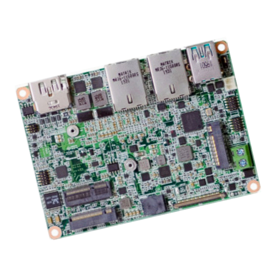
Chapter 2 HARDWARE INSTALLATION Chapter 2 - Hardware Installation Note: Some components are optional and only available upon request. X Board Layout Important: Electrostatic discharge (ESD) can damage your board, processor, disk drives, add-in boards, and other components. Perform installation procedures at an ESD workstation only. If such a station is not available, you can provide some ESD protection by wearing an antistatic wrist strap and attaching it to a metal part of the system chassis. -
Page 9: Chapter 2 - Hardware Installation
Chapter 2 HARDWARE INSTALLATION X System Memory System Memory Installing the Memory Module Before installing the memory module, please make sure that the following safety cautions are well-attended. 1. Make sure the PC and all other peripheral devices connected to it has been powered down. -
Page 10: System Memory
Chapter 2 HARDWARE INSTALLATION System Memory Installing the Memory Module System Memory Removing the Memory Module Please follow the steps below to install the memory card into the socket. Please follow the steps below to remove the memory card from the socket. Step 1: Step 1: Press the eject tabs at both ends of the socket outward and downward to release them from... -
Page 11: Removing The Memory Module
Chapter 2 HARDWARE INSTALLATION Installing the Heat Sink The CPU must be kept cool by using a heat sink, otherwise the CPU will overheat damaging A heat spreader is included in the standard package. The heat spreader and components both the CPU and system board. required for mounting are illustrated below. -
Page 12: Installing The Heat Sink
Chapter 2 HARDWARE INSTALLATION Rotate the module and heat spreader combo so that the I/O is facing the desired side, and e t a l place the combo in the position of the chassis reserved for your module. r f a c I n t e Align the screw holes of the combo to those on the chassis. -
Page 13: Jumper Settings
Chapter 2 HARDWARE INSTALLATION X Jumper Settings Clear CMOS If any anomaly of the followings is encountered — a) CMOS data is corrupted; b) you forgot the supervisor or user password; c) failure to start the system due to BIOS mis-configuration —... -
Page 14: Rear I/O Ports
Chapter 2 HARDWARE INSTALLATION X Rear I/O Ports Rear I/O Ports USB Ports Rear „ USB 3.1 Gen 2 „ LAN 1 „ LAN 2 „ DP++/HDMI Side „ eDP The rear panel I/O ports consist of the following: „ USB 3.1 Gen 2 •... -
Page 15: Graphics Display
Chapter 2 HARDWARE INSTALLATION Rear I/O Ports Rear I/O Ports Graphics Display „ LAN 1 „ LAN 2 „ DP++/HDMI DisplayPort ++ LAN1/LAN2 (RJ45) The DisplayPort (DP) is a digital display interface used to connect a display device such as a The onboard RJ45 LAN port allows the system board to connect to a local area network by computer monitor. -
Page 16: Graphics Display
Chapter 2 HARDWARE INSTALLATION Rear I/O Ports Graphics Display „ eDP Pin Assignment (Horizontal Slot) „ eDP Pin Assignment (Vertical Slot) Assignment Assignment Assignment Assignment eDP_PANEL_PWR eDP_PANEL_PWR eDP_TXN3 eDP_TXN3 eDP_TXP3 eDP_TXP3 eDP_TXN2 eDP_TXN2 eDP_TXP2 eDP_HPD_CN eDP_TXP2 eDP_HPD_C eDP_TXN1 eDP_TXN1 eDP_TXP1 eDP_TXP1 eDP_TXN0 BLONOFF... -
Page 17: Internal I/O Connectors
Chapter 2 HARDWARE INSTALLATION X Internal I/O Connectors SMBus The SMBus (System Management Bus) connector is used to connect the SMBus device. It is a multiple device bus that allows multiple chips to connect to the same bus and enable each one to act as a master by initiating data transfer. -
Page 18: Usb Ports
Chapter 2 HARDWARE INSTALLATION Internal I/O Connectors USB Ports The USB device allows data exchange between your computer and a wide range of simultaneously accessible external Plug and Play peripherals. The internal USB pin headers may be connected to a card-edge bracket. Install the card-edge „... -
Page 19: Front Audio
Chapter 2 HARDWARE INSTALLATION Internal I/O Connectors Internal I/O Connectors Front Audio Digital I/O The Digital I/O (DIO) connector allows for input/output signals of digital logical states defined by voltage levels. The Front Audio internal connector allows you to connect to the second line-out and mic-in jacks that are at the front panel of your system. -
Page 20: Power Connector
Chapter 2 HARDWARE INSTALLATION Internal I/O Connectors Power Connector „ 2-pin Power Connector 1 (+): +12V 2 (-): GND This 2-pin terminal block is considered a low power solution. Connect a DC power cord to this terminal block by inserting the wire into the block and then screw tight the screw on top to secure the wire in place. -
Page 21: Front Panel
Chapter 2 HARDWARE INSTALLATION Internal I/O Connectors Front Panel PWR-LED - Power/Standby LED When the system’s power is on, this LED will light. When the system is in the S1 (POS - Power On Suspend) state, it will blink every second. When the system is in the S3 (STR - Suspend To RAM) state, it will blink every 4 seconds. -
Page 22: Battery Header
Chapter 2 HARDWARE INSTALLATION Internal I/O Connectors Battery Header „ Battery Header The lithium ion battery powers the real-time clock and CMOS memory. It is an auxiliary source of power when the main power is shut off. A battery wrapped with an adhesive tape connects to the header, the tape helps position the bat- tery at a proper place in the case. -
Page 23: Chapter 3 - Bios Settings
Chapter 3 BIOS SETTINGS Chapter 3 - BIOS Settings Legends X Overview Keys Function The BIOS is a program that takes care of the basic level of communication between the CPU and peripherals. It contains codes for various advanced features found in this system board. Right / Left arrow Move the highlight left or right to select a menu The BIOS allows you to configure the system and save the configuration in a battery-backed... -
Page 24: Main
Chapter 3 BIOS SETTINGS X Main X Advanced The Main menu is the first screen that you will see when you enter the BIOS Setup Utility. The Advanced menu allows you to configure your system for basic operation. Some entries are defaults required by the system board, while others, if enabled, will improve the performance of your system or let you set some features according to your preference. -
Page 25: Rc Acpi Configuration
Chapter 3 BIOS SETTINGS Advanced Advanced RC ACPI Configuration CPU Configuration Wake system from S5 Intel (VMX) Virtualization Technology When Enabled, the system will automatically power up at a designated time every day. Once When this field is set to Enabled, the VMM can utilize the additional hardware capabilities it’s switched to [Enabled], please set up the time of day including hour, minute, and second provided by Vanderpool Technology. -
Page 26: Power & Performance
Chapter 3 BIOS SETTINGS Advanced Advanced Power & Performance PCH-FW Configuration Intel(R) SpeedStep(tm) ME State This field is used to enable or disable the Intel SpeedStep Technology, which helps optimize When this field is set to Disabled, ME will be put into ME Temporarily Disabled Mode. ®... - Page 27 Chapter 3 BIOS SETTINGS Advanced PCH-FW Configuration Advanced PCH-FW Configuration ► AMT Configuration ► AMT Configuration ► Secure Erase Configuration USB Provisioning of AMT Secure Erase Mode Enable or disable AMT USB Provisioning. Select Secure Erase module behavior: Simulated or Real. Force Secure Erase Enable or disable Force Secure Erase on next boot.
- Page 28 Chapter 3 BIOS SETTINGS Advanced PCH-FW Configuration Advanced PCH-FW Configuration ► AMT Configuration ► OEM Flags Settings ► Firmware Update Configuration Hide Unconfigure ME Confirmation Prompt Me FW Image Re-Flash Enable or disable to hide unconfigure ME confirmation prompt when attempting to unconfigure This field is used to enable or disable the ME FW Image Re-Flash function, which allows the user to update the ME firmware.
-
Page 29: Trusted Computing
Chapter 3 BIOS SETTINGS Advanced Advanced Trusted Computing NCT5525D Super IO Configuration Security Device Support WatchDog Timer Unit This field is used to enable or disable BIOS support for the security device such as TPM 2.0 to Select WatchDog Timer Unit — Second or Minute. achieve hardware-level security via cryptographic keys. -
Page 30: Nct5525D Hw Monitor
Chapter 3 BIOS SETTINGS Advanced NCT5525D Super IO Configuration Advanced ► Serial Port Configuration NCT5525D HW Monitor This section displays the system’s health information, i.e. voltage readings, CPU and system Serial Port temperatures. Enable or disable the current serial COM port. RS485 Auto Flow Enable or disable RS485 auto flow. -
Page 31: Serial Port Console Redirection
Chapter 3 BIOS SETTINGS Advanced Advanced Serial Port Console Redirection Serial Port Console Redirection ► Console Redirection Settings Configure the serial settings of the current COM port. Console Redirection Terminal Type By enabling Console Redirection of a COM port, the sub-menu of console redirection settings Select terminal type: VT100, VT100+, VT-UTF8 or ANSI. -
Page 32: Usb Configuration
Chapter 3 BIOS SETTINGS Advanced Advanced USB Configuration CSM Configuration Legacy USB Support CSM Support Enabled Enable Legacy USB support. This section is used to enable or disable CSM Support. The following fields are only available Disabled Keep USB devices available only for EFI applications. when "CSM Support"... -
Page 33: Usb Power Control
Chapter 3 BIOS SETTINGS Advanced Advanced USB Power Control Network Stack Configuration 5V / 5V_DUAL Network Stack 5V Dual supports wake up from S3/S4 state by USB keyboard or mouse while 5V does not. Enable or disable UEFI network stack. The following fields will appear when this field is enabled. -
Page 34: Chipset
Chapter 3 BIOS SETTINGS X Chipset Chipset Graphics Configuration To configure graphics and PCH-IO relevant settings. Primary Display Select which of IGFX/PEG/PCI Graphics device to be the primary display. Internal Graphics Keep IGFX enabled based on the setup options. User's Manual | WL051... -
Page 35: Pch-Io Configuration
Chapter 3 BIOS SETTINGS Chipset Chipset PCH-IO Configuration PCH-IO Configuration PCI Express Configuration Select one of the PCI Express channels and press enter to configure the following settings. LAN1(I219) PCI Express Devices Enable or disable onboard NIC. Enable or disable the PCI Express Root Port. Wake on LAN Enable PCIe Speed Enable or disable integrated LAN to wake the system. -
Page 36: Sata And Rst Configuration
Chapter 3 BIOS SETTINGS Advanced Chipset PCH-IO Configuration SATA And RST Configuration HD Audio Configuration SATA Controller(s) HD Audio This field is used to enable or disable the Serial ATA controller. Control the detection of the HD Audio device. SATA Speed Disabled HDA will be unconditionally disabled. -
Page 37: Security
Chapter 3 BIOS SETTINGS X Security Security Secure Boot Administrator Password Secure Boot Set the administrator password. To clear the password, input nothing and press enter when a The Secure Boot store a database of certificates in the firmware and only allows the OSes with authorized signatures to boot on the system. - Page 38 Chapter 3 BIOS SETTINGS Security Secure Boot X Key Management • “PK” for Platform Keys • “KEK” for Key Exchange Keys • “db” for Authorized Signatures • “dbx” for Forbidden Signatures Enroll Efi Image Allow the image to run in Secure Boot mode. Enroll SHA256 Hash certificate of a PE image into Authorized Signature Database (db).
-
Page 39: Boot
Chapter 3 BIOS SETTINGS X Boot X Save & Exit Setup Prompt Timeout Save Changes and Reset Set the number of seconds to wait for the setup activation key. 65535 (0xFFFF) denotes To save the changes, select this field and then press <Enter>. A dialog box will appear. Select indefinite waiting. -
Page 40: Updating The Bios
BIOS with the flash utility. For updating AMI BIOS in UEFI mode, you may refer to the how-to video at https://www.dfi.com/Knowledge/Video/5. X Notice: BIOS SPI ROM 1. -
Page 41: Chapter 4 - Intel Amt Settings
Chapter 4 INTEL AMT SETTINGS Chapter 4 - Intel AMT Settings X Enable Intel AMT in the AMI BIOS ® X Overview 1. Power-on the system then press <Del> to enter the main menu of the AMI BIOS. 2. In the Advanced menu, select PCH-FW Configuration. Intel Active Management Technology (Intel AMT) combines hardware and software solution to ®... -
Page 42: Entering Management Engine Bios Extension (Mebx)
Chapter 4 INTEL AMT SETTINGS Enable Intel AMT in the AMI BIOS X Entering Management Engine BIOS Extension (MEBX) ® 4. Press F4, or go to the Save & Exit menu, select Save Changes and Reset and then press <Enter>. A dialog box will appear. Select Yes and press Enter to reset the system after saving all changes made. -
Page 43: Mebx
Chapter 4 INTEL AMT SETTINGS X MEBX Intel(R) ME General Settings Main Menu Select Intel(R) ME General Settings under Main Menu and then press Enter. Select MEBx Login under Main Menu and press Enter. A prompt that requires password input will show up. - Page 44 Chapter 4 INTEL AMT SETTINGS MEBX Intel(R) ME General Settings MEBX Intel(R) ME General Settings Change ME Password Local FW Update If you want to change ME password, select Change ME Password and then press Enter. A Select Local FW Update then press Enter. Select Enabled or Disabled or Password Protected prompt that requires password input will show up.
-
Page 45: Enable Intel
Chapter 4 INTEL AMT SETTINGS MEBX Intel(R) Standard Manageability > SOL/Storage Redirection/KVM Enable Intel(R) Standard Manageability under Main Menu to show relevant options. Press Enter to enter the submenu. Manageability Feature Selection Select Enabled or Disabled then press Enter. When disabled, all the following fields will be hidden. - Page 46 Chapter 4 INTEL AMT SETTINGS MEBX Intel(R) Standard Manageability Configuration MEBX Intel(R) Standard Manageability Configuration > SOL/Storage Redirection/KVM > User Consent Move the cursor to select a field and press Enter to display options. Press Enter to enter the submenu. Select Enabled or Disabled then press Enter.
- Page 47 Chapter 4 INTEL AMT SETTINGS MEBX Intel(R) Standard Manageability Configuration MEBX Intel(R) Standard Manageability Configuration > User Consent Password Policy Move the cursor to select a field and press Enter to display options. Under the Intel(R) Standard Manageability Configuration menu, select Password Policy then press Enter.
- Page 48 Chapter 4 INTEL AMT SETTINGS MEBX Intel(R) Standard Manageability Configuration > Network Setup Move the cursor to select a field and press Enter to display options. Under the Intel(R) Standard Manageability Configuration menu, select Network Setup and then press Enter. Host Name Enter the computer’s host name and then press Enter.
- Page 49 Chapter 4 INTEL AMT SETTINGS MEBX Intel(R) Standard Manageability Configuration Network Setup MEBX Intel(R) Standard Manageability Configuration Network Setup Intel(R) ME Network Name Settings > TCP/IP Settings DHCP Mode Under the Intel(R) ME Network Setup menu, select TCP/IP Settings and then press Enter. Select Enabled or Disabled then press Enter.
- Page 50 Chapter 4 INTEL AMT SETTINGS MEBX Intel(R) Standard Manageability Configuration Network Setup Activate Network Access TCP/IP Settings Select Activate Network Access and press Enter, and then press Y to activate the ME network connection with the settings configured previously, or press N to abort. IPv4 Address Assign a valid and available IP address to the system.
- Page 51 Chapter 4 INTEL AMT SETTINGS MEBX Intel(R) Standard Manageability Configuration > Remote Setup And Configuration Under the Intel(R) Standard Manageability Configuration menu, select Remote Setup And Current Provisioning Mode Configuration then press Enter. The current mode — Public Key Infrastructure (PKI) — is displayed. Provisioning Record Press Enter to view the record.
- Page 52 Chapter 4 INTEL AMT SETTINGS MEBX Intel(R) Standard Manageability Configuration Remote Setup And Configuration MEBX Intel(R) Standard Manageability Configuration Remote Setup And Configuration > RCFG > TLS PKI Press Enter, select Start Configuration, and then press Enter to activate Remote Configuration The system adopts PKI for encryption and authentication, and the TLS protocol for (RCFG).
- Page 53 Chapter 4 INTEL AMT SETTINGS MEBX Intel(R) Standard Manageability Configuration Remote Setup And Configuration MEBX Intel(R) Standard Manageability Configuration TLS PKI > Power Control Under the Intel(R) Standard Manageability Configuration menu, select Power Control then > Manage Hashes press Enter. Select a hash name and then press the following keys to execute a function.
- Page 54 Chapter 4 INTEL AMT SETTINGS MEBX MEBx Exit Under the Main Menu, select MEBx Exit and then press Enter. Press Y to confirm or N to abort. User's Manual | WL051 ver.0A_MVT_3-1921_15...
Need help?
Do you have a question about the WL051-BCC-4305UE and is the answer not in the manual?
Questions and answers