Table of Contents
Advertisement
Quick Links
Advertisement
Table of Contents

Related Manuals for DFI WL171


Summary of Contents for DFI WL171
- Page 1 WL171/WL173 Mini-ITX Industrial Motherboard User’s Manual A-569-M-2018...
- Page 2 1. The changes or modifications not expressly approved by the party responsible for com- pliance could void the user’s authority to operate the equipment. 2. Shielded interface cables must be used in order to comply with the emission limits. User's Manual | WL171/WL173...
-
Page 3: Table Of Contents
Main ..............................28 Advanced ............................28 RC ACPI Configuration ......................29 CPU Configuration ........................ 29 Power & Performance ......................30 PCH-FW Configuration ......................30 Trusted Computing ....................... 31 PTN3460 Configuration ....................... 31 NCT6116D Super IO Configuration..................32 User's Manual | WL171/WL173... - Page 4 • To reduce the risk of electric shock, unplug the power cord before removing the sys- tem chassis cover for installation or servicing. After installation or servicing, cover the system chassis before plugging the power cord. User's Manual | WL171/WL173...
- Page 5 • An RS232 extension part is integrated on the board. • Heatsink A71-008155-010G, 141.2*82*36mm, SPRING-SCREW TYPE, FOR WL171 Wide Temp • Heatsink A71-008155-000G, 141.2*82*26mm, SPRING-SCREW TYPE, FOR WL171 The board and accessories in the package may not come similar to the information listed above.
-
Page 6: Chapter 1 - Introduction
HW Decode: AVC/H.264, MPEG2, VC1/WMV9, JPEG/MJPEG, SECURITY TPM 2.0 (Opt.) HEVC/H265, VP8, VP9 POWER Type Single 12V +/-10% DC (WL171) HW Encode: AVC/H.264, MPEG2, JPEG, HEVC/H265, VP8, VP9 Wide Range 9~36V (WL173) Display 1 x LVDS resolution up to 1920x1200 @ 60Hz Connector... -
Page 7: Features
Event) signal. However, if your system is in the Suspend mode, you can power-on the system only through an IRQ or DMA interrupt. Wake-On-USB This function allows you to use a USB keyboard or USB mouse to wake up a system from the S3 (STR - Suspend To RAM) state. User's Manual | WL171/WL173... -
Page 8: Chapter 2 - Hardware Installation
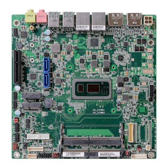
Failure to do CPU FAN SATA0 LED1 so will cause severe damage to the motherboard and compo- nents. Note: Some of the components are model-specific. Please refer to the specifications for detail. User's Manual | WL171/WL173... -
Page 9: System Memory
DIMMs. Not all slots need to be populated. Dual Channel DIMMs of the same memory configuration are on different channels. Features • 2 x 260-pin SODIMM up to 64GB • DDR4 2400MHz (Celeron 4305UE 2133MHz only) 4 5 ° Step 1 User's Manual | WL171/WL173... -
Page 10: Heatsink
Inspect that the clip sits in the notch. If not, please pull the clips outward, release and remove the Step 3 card, and mount it again. User's Manual | WL171/WL173... - Page 11 Chapter 2 HARDWARE INSTALLATION Heatsink Note: The standard package of WL171/173 only includes a heatsink. Interface Metal The heatsink included in the standard package is de- signed to dissipate heat from both the CPU and the memory. Please orient the heatsink so that the interface metal sits on top the CPU and the heatsink also hov- ers the memory.
-
Page 12: Jumper Settings
M.2 M Key Front Panel SYS FAN SMBUS LED3 M.2 M Key Front Panel M.2 E Key SPI Flash BIOS SATA1 LED2 M.2 E Key SPI Flash BIOS SATA1 LED2 CPU FAN SATA0 LED1 CPU FAN SATA0 LED1 User's Manual | WL171/WL173... -
Page 13: Panel Power Select (Jp4)
SYS FAN DIO Power M.2 E Key SPI Flash BIOS SATA1 LED2 YS FAN SMBUS LED3 M.2 M Key Front Panel CPU FAN SATA0 LED1 M.2 E Key SPI Flash BIOS SATA1 LED2 User's Manual | WL171/WL173 CPU FAN SATA0 LED1... -
Page 14: Com1 Power Select
JP2 (COM 1). Standard RS232 (default) RS232 with Power „ 2-4 On: Pin 1 = DCD- „ 4-6 On: Pin 1 = +12V „ 1-3 On: Pin 9 = RI- „ 3-5 On: Pin 9 = +5V User's Manual | WL171/WL173... -
Page 15: Rear I/O Ports
Mic In Line Out The rear panel I/O ports consist of the following: The votalge range is model-specific — 12VDC for WL171, and 9V~36V for WL173. • 2 HDMI/DP++ ports Connect a coaxial DC power cord to the rear coaxial connector for DC supply. The 4-pin vertical / right-angle type is avaible upon request. -
Page 16: Usb Ports
Type A ports at the rear side. For the internal USB ports, please refer to the next section. Wake-On-USB Keyboard/Mouse The Wake-On-USB Keyboard/Mouse function allows you to use a USB keyboard or USB mouse to wake up a system from the S3 (STR - Suspend To RAM) state. User's Manual | WL171/WL173... -
Page 17: Rj45 Lan
This jack is used to connect a headphone or external speakers. • Mic-in Jack (Pink) Features This jack is used to connect an external microphone. • LAN1: Intel ® I219LM LAN PHY • LAN2: Intel ® I210AT PCIe Gigabit Ethernet LAN Controller User's Manual | WL171/WL173... -
Page 18: Internal I/O Connectors
DSR- N.C. N.C. The Wake-On-USB Keyboard/Mouse function allows you to use a USB keyboard or USB mouse RTS- RTS- N.C. N.C. to wake up a system from the S state(s). CTS- CTS- N.C. N.C. N.C. N.C. User's Manual | WL171/WL173... -
Page 19: Front Audio
Pin Assignment „ SATA Pin Assignment „ SATA Power Pin Assignment Mic-L +12V Mic-R N.C. Front-Out-R Mic-JD (sense) SMBUS LED3 M.2 M SYS FAN Front-Out-JD Front-Out-L (sense) SPI Flash BIOS SATA1 LED2 CPU FAN SATA0 LED1 User's Manual | WL171/WL173... -
Page 20: Chassis Intrusion
M.2 E Key SPI Flash BIOS SATA1 LED2 CPU FAN SATA0 LED1 „ Chassis Intrusion Pin Assignment „ FAN Pin Assignment Pin Assignment Pin Assignment Pin Assignment Signal Sense User's Manual | WL171/WL173... -
Page 21: Front Panel
Power On Suspend) state, it will blink at 1-second intervals. When the system is in the S3 (STR - Suspend To RAM) state, it will blink at 4-second intervals. ATX-SW - ATX Power Switch This switch is used to power on or off the system. User's Manual | WL171/WL173... -
Page 22: Battery
DIO_4 • The battery is wrapped by an adhesive tape which helps integrator properly places the battery in the system case, a stable position and appropriate temperature will last the DIO_5 functionality of it. DIO_6 DIO_7 User's Manual | WL171/WL173... -
Page 23: Lvds Panel
USB 5/6 (USB 2.0) 2.0) DDC_DATA +3.3V Panel Backlight On/Off Con- trol Panel Power Panel Inverter Brightness 12V (default)/5V Voltage Control Panel Power Panel Power COM1 Panel Power 12V (default)/5V COM2 Chassis Intrusion SATA Power User's Manual | WL171/WL173 DIO Power... -
Page 24: Edp
Front Audio Inverter PWR eDP Panel PWR Inverter PWR Buzzer eDP Panel PWR Inverter PWR PCIE1 (PCIe x4) eDP Panel PWR N.C. 2.0) USB 7/8 (USB 2.0) USB 5/6 (USB 2.0) 2.0) COM1 COM2 User's Manual | WL171/WL173 Chassis Intrusion... -
Page 25: Expansion Slots
80mm) and the M.2 E key sicket (22mm x 30mm). PCI Express x4 Slot Install PCI Express cards such as network cards or other cards that comply to the PCI Express specifications into the PCI Express x4 slot. User's Manual | WL171/WL173... -
Page 26: Lpc
The L_LAD3 card should be lying parallel to LAN2 the board when it’s correctly L_LAD2 mounted. SERIRQ USB 1/2 5VSB (USB 3.0/2.0) USB 3/4 (USB 3.0/2.0) User's Manual | WL171/WL173 Mic In... -
Page 27: Chapter 3 - Bios Settings
When “X” appears on the left of a particular field, it indicates that a submenu which contains additional options are available for that field. To display the submenu, move the highlight to that field and press <Enter>. User's Manual | WL171/WL173... -
Page 28: Main
The time format is <hour>, <minute>, <second>. The time is based on the 24-hour military- time clock. For example, 1 p.m. is 13:00:00. Hour displays hours from 00 to 23. Minute displays minutes from 00 to 59. Second displays seconds from 00 to 59. User's Manual | WL171/WL173... -
Page 29: Rc Acpi Configuration
S5 State - Off, except for trickle current to devices such as the power button Last State - The state before G3. Note: Some of the fields may not be available when the features are not supported by the equipped CPU. User's Manual | WL171/WL173... -
Page 30: Power & Performance
> Me FW Image Re-Flash enabled. Enable or disable Me FW Image Re-Flash function. C states Enable or disable CPU Power Management. It allows CPU to enter "C states" when it’s idle and nothing is executing. User's Manual | WL171/WL173... -
Page 31: Trusted Computing
1280X768, 1920X1080, or 1600X900. LCD Panel Color Depth Select the color depth of the LCD Panel — 18 Bit, 24 Bit, 36 Bit, 48 Bit. Backlight Type Select the inverter polarity and brightness control — PWM Mdde, DC Mdde User's Manual | WL171/WL173... -
Page 32: Nct6116D Super Io Configuration
Set SuperIO WatchDog Timer Timeout value. The range is from 0 (disabled) to 255. Enable or disable RS485 auto flow. This field is only available for COM ports that support RS485 mode. Note: The sub-menus are detailed in following sections. User's Manual | WL171/WL173... -
Page 33: Nct6116D Hw Monitor
Set the fan speed. The range is from 1-100% (full speed). Note: CPU Smart Fan Control, System Smart Fan(1) Control can be switched to [Disabled]. When they are disabled, "Fix Fan Speed Count" will appear for configuration. User's Manual | WL171/WL173... -
Page 34: Serial Port Console Redirection
Console Redirection Manual PWM Setting By enabling Console Redirection of a COM port, the sub-menu of console redirection settings Choose a value from 1~100 of fan speed. will become available for configuration as detailed in the following. User's Manual | WL171/WL173... -
Page 35: Usb Configuration
Enable or disable USB Mass Storage Driver Support. Parity Select parity bits: None, Even, Odd, Mark or Space. Stop Bits Select stop bits: 1 bit or 2 bits. Flow Control Select flow control type: None or Hardware RTS/CTS. User's Manual | WL171/WL173... -
Page 36: Csm Configuration
This field controls the execution of UEFI and Legacy Storage OpROM. Video This field controls the execution of UEFI and Legacy Video OpROM. Other PCI devices This field determines OpROM execution policy for devices other than Network, Storage or Video. User's Manual | WL171/WL173... -
Page 37: Network Stack Configuration
Set the wait time in seconds to press ESC key to abort the PXE boot. Use either +/- or numeric keys to set the value. Media detect count Set the number of times the presence of media will be checked. Use either +/- or numeric keys to set the value. User's Manual | WL171/WL173... -
Page 38: Chipset
Version 2.20.1275. Copyright (C) 2020 American Megatrends, Inc. Version 2.20.1275. Copyright (C) 2020 American Megatrends, Inc. Primary Display Select which of IGFX/PEG/PCI Graphics device to be the primary display. Internal Graphics Keep IGFX enabled based on the setup options. User's Manual | WL171/WL173... -
Page 39: Pch-Io Configuration
Enable or disable hot plug function of the port. This field may not appear when the port does Assign a value or set “Dynamic” to automatically adjust TOLUD based on largest MMIO length not support hot plug. User's Manual | WL171/WL173... -
Page 40: Sata And Rst Configuration
This field shows up when SATA Mode Selection is set to Intel RST Premium With Intel Optane System Acceleration. Enable or disable to use RST Legacy OROM when CSM is enabled. Port and Hot Plug Enable or disable the Serial ATA port and its hot plug function. User's Manual | WL171/WL173... -
Page 41: Security
Secure Boot. Press Enter and a prompt will show up for you to confirm. Reset To Setup Mode Clear the database from the NVRAM, including all the keys and signatures installed in the Key Management menu. Press Enter and a prompt will show up for you to confirm. User's Manual | WL171/WL173... - Page 42 Export the Secure Boot settings (i.e. all keys and signatures) as files to the root directory of a file system device. Press Enter and select a storage device listed in the pop-up menu. The saved files will be named automatically according to the type of key/signature as listed below. User's Manual | WL171/WL173...
-
Page 43: Boot
“Quiet Boot” is set to enabled, “BGRT Logo” will show up for configura- This field will appear only when a USB flash device is detected. Select this field to restore set- tion. Refer to the Advanced > CSM Configuration for more information. ting from the USB flash device. User's Manual | WL171/WL173... -
Page 44: Updating The Bios
When the BIOS IC needs to be replaced, you have to populate it properly onto the system board after the EEPROM programmer has been burned and follow the technical person's instructions to confirm that the MAC address should be burned or not. User's Manual | WL171/WL173... -
Page 45: Chapter 4 - Raid
4. Press F10 to save the changes. Block-level data striping with RAID 5 Single Drive Failure distributed parity 5. Reboot the system. 1 Disk Per Mirrored Combination of RAID 0 (data striping) RAID 10 Stripe (not same mirror) and RAID 1 (mirroring) User's Manual | WL171/WL173... - Page 46 5. Press <Enter>. 6. Use the up or down arrow keys to select the strip size and press <Enter>. 7. Enter the volume size and press <Enter>. 8. At the prompt, press <Y> to confirm volume creation. User's Manual | WL171/WL173 ver.A1_DVT_10-1920_10-48...
Need help?
Do you have a question about the WL171 and is the answer not in the manual?
Questions and answers