Table of Contents
Advertisement
Quick Links
Advertisement
Table of Contents

Subscribe to Our Youtube Channel
Related Manuals for DFI WL053-BCA-4305UE


Summary of Contents for DFI WL053-BCA-4305UE
- Page 1 WL053 2.5" Pico-ITX Motherboard User’s Manual ver.0A_MVT_3-3121_16-34...
-
Page 2: Fcc And Doc Statement On Class B
Copyright FCC and DOC Statement on Class B This publication contains information that is protected by copyright. No part of it may be This equipment has been tested and found to comply with the limits for a Class B digital reproduced in any form or by any means or used to make any transformation/adaptation device, pursuant to Part 15 of the FCC rules. - Page 3 Table of Contents Chapter 3 - BIOS Settings ......................22 Overview ..........................22 Main ............................23 Chapter 1 - Introduction........................ 6 Advanced ..........................23 Specifications ......................... 6 RC ACPI Configuration ....................24 Features ..........................7 CPU Thermal Configuration ..................24 Power & Performance ....................25 Chapter 2 - Hardware Installation ....................8 PCH-FW Configuration ....................25 Board Layout...........................
-
Page 4: About This Manual
About this Manual Static Electricity Precautions This manual can be downloaded from the website. It is quite easy to inadvertently damage your PC, system board, components or devices even before installing them in your system unit. Static electrical discharge can damage computer The manual is subject to change and update without notice, and may be based on editions components without causing any signs of physical damage. -
Page 5: About The Package
Before Using the System Board About the Package When installing the system board in a new system, you will need at least the following internal The package contains the following items. If any of these items are missing or damaged, components. -
Page 6: Specifications
Chapter 1 INTRODUCTION Chapter 1 - Introduction Power Type Wide Range 9~36V Connector 2-pin Terminal Block Consumption Typical: 8665UE:12V @ 0.43A (5.16Watt) X Specifications Max.: 8665UE:12V @ 2.91A (34.92Watt) RTC Battery CR2032 Coin Cell ® System Processor 8th Generation Intel Core™... - Page 7 Chapter 1 INTRODUCTION X Features ACPI STR Watchdog Timer The system board is designed to meet the ACPI (Advanced Configuration and Power The Watchdog Timer function allows your application to regularly “clear” the system at the set Interface) specification. ACPI has energy saving features that enables PCs to implement time interval.
-
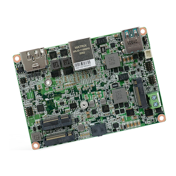
Page 8: Board Layout
Chapter 2 HARDWARE INSTALLATION Chapter 2 - Hardware Installation Note: Some components are optional and only available upon request. X Board Layout Important: Electrostatic discharge (ESD) can damage your board, processor, disk drives, add-in boards, and other components. Perform Top View installation procedures at an ESD workstation only. -
Page 9: System Memory
Chapter 2 HARDWARE INSTALLATION X System Memory System Memory Installing the Memory Module Before installing the memory module, please make sure that the following safety cautions are well-attended. 1. Make sure the PC and all other peripheral devices connected to it has been powered down. -
Page 10: Removing The Memory Module
Chapter 2 HARDWARE INSTALLATION System Memory Installing the Memory Module System Memory Removing the Memory Module Please follow the steps below to install the memory card into the socket. Please follow the steps below to remove the memory card from the socket. Step 1: Step 1: Press the eject tabs at both ends of the socket outward and downward to release them from... - Page 11 Chapter 2 HARDWARE INSTALLATION Installing the Heat spreader The CPU must be kept cool by using a heat spreader, otherwise the CPU will overheat A heat spreader is included in the standard package. The heat spreader and components damaging both the CPU and system board. required for mounting are illustrated below.
- Page 12 Chapter 2 HARDWARE INSTALLATION Rotate the module and heat spreader combo so that the I/O is facing the desired side, and e t a l place the combo in the position of the chassis reserved for your module. r f a c I n t e Align the screw holes of the combo to those on the chassis.
-
Page 13: Jumper Settings
Chapter 2 HARDWARE INSTALLATION X Jumper Settings Clear CMOS UBCN1 M2CN3.G3 M2CN1 M2CN3 CN13 CN14 If any anomaly of the followings is encountered — a) CMOS data is corrupted; b) you forgot the supervisor or user password; c) failure to start the system due to BIOS mis-configuration —... -
Page 14: Rear I/O Ports
Chapter 2 HARDWARE INSTALLATION X Rear I/O Ports Rear I/O Ports USB Ports Rear „ USB 3.1 Gen 2 „ LAN „ DP++/HDMI UBCN1 M2CN3.G3 M2CN1 M2CN3 CN13 CN14 The rear panel I/O ports consist of the following: • 1 HDMI / DP++ port „... -
Page 15: Graphics Display
Chapter 2 HARDWARE INSTALLATION Rear I/O Ports Rear I/O Ports Graphics Display UBCN1 UBCN1 M2CN3.G3 M2CN3.G3 M2CN1 M2CN1 M2CN3 M2CN3 CN13 CN13 CN14 CN14 „ USB 3.1 Gen 2 „ USB 3.1 Gen 2 „ LAN „ LAN „ DP++/HDMI „... -
Page 16: Internal I/O Connectors
Chapter 2 HARDWARE INSTALLATION X Internal I/O Connectors SMBus CPU Fan HDMI_DP HDMI_DP USB3_1/2 USB3_1/2 Intel Intel BGA 1528 BGA 1528 SM_BUS SM_BUS WL051 WL051 AUJ1 AUJ1 SO_DIMM1 SO_DIMM1 DDR4 SODIMM DDR4 SODIMM Front Audio Front Audio REV.1 REV.1 The SMBus (System Management Bus) connector is used to connect the SMBus device. It is a The CPU Fan connector is used to connect the CPU fan. - Page 17 Chapter 2 HARDWARE INSTALLATION Internal I/O Connectors USB Ports The USB device allows data exchange between your computer and a wide range of „ USB 6/7 (USB 2.0) simultaneously accessible external Plug and Play peripherals. The internal USB pin headers may be connected to a card-edge bracket. Install the card-edge bracket to an available slot at the rear of the system chassis and then insert the USB port cables to a connector.
- Page 18 Chapter 2 HARDWARE INSTALLATION Internal I/O Connectors Internal I/O Connectors Digital I/O COM1 UBCN1 UBCN1 M2CN3.G3 M2CN3.G3 M2CN1 M2CN1 M2CN3 M2CN3 CN13 CN13 CN14 CN14 The Digital I/O (DIO) connector allows for input/output signals of digital logical states defined COM 1 can be selected among RS232, RS422 and RS485 via BIOS setting. by voltage levels.
-
Page 19: Power Connector
Chapter 2 HARDWARE INSTALLATION Internal I/O Connectors Power Connector UBCN1 M2CN3.G3 „ 2-pin Power Connector 1 (+): +12V M2CN1 2 (-): GND M2CN3 CN13 CN14 This 2-pin terminal block is considered a low power solution. Connect a DC power cord to this terminal block by inserting the wire into the block and then screw tight the screw on top to secure the wire in place. - Page 20 Chapter 2 HARDWARE INSTALLATION Internal I/O Connectors Front Panel PWR-LED - Power/Standby LED When the system’s power is on, this LED will light. When the system is in the S1 (POS - Power On Suspend) state, it will blink every second. When the system is in the S3 (STR - Suspend To RAM) state, it will blink every 4 seconds.
- Page 21 Chapter 2 HARDWARE INSTALLATION Internal I/O Connectors Battery Header UBCN1 „ Battery Header M2CN3.G3 M2CN1 M2CN3 CN13 CN14 The lithium ion battery powers the real-time clock and CMOS memory. It is an auxiliary source of power when the main power is shut off. A battery wrapped with an adhesive tape connects to the header, the tape helps position the bat- tery at a proper place in the case.
-
Page 22: Chapter 3 - Bios Settings
Chapter 3 BIOS SETTINGS Chapter 3 - BIOS Settings Legends X Overview Keys Function The BIOS is a program that takes care of the basic level of communication between the CPU and peripherals. It contains codes for various advanced features found in this system board. Right / Left arrow Move the highlight left or right to select a menu The BIOS allows you to configure the system and save the configuration in a battery-backed... - Page 23 Chapter 3 BIOS SETTINGS X Main X Advanced The Main menu is the first screen that you will see when you enter the BIOS Setup Utility. The Advanced menu allows you to configure your system for basic operation. Some entries are defaults required by the system board, while others, if enabled, will improve the performance of your system or let you set some features according to your preference.
-
Page 24: Cpu Thermal Configuration
Chapter 3 BIOS SETTINGS Advanced Advanced RC ACPI Configuration CPU Thermal Configuration Aptio Setup Utility - Copyright (C) 2019 American Megatrends, Inc. Aptio Setup Utility - Copyright (C) 2019 American Megatrends, Inc. Advanced Advanced CPU Thermal Configuration Offset from factory set Tcc RC ACPI Configuration Enable or disable System activation termerature at... -
Page 25: Power & Performance
Chapter 3 BIOS SETTINGS Advanced Advanced Power & Performance PCH-FW Configuration Aptio Setup Utility - Copyright (C) 2019 American Megatrends, Inc. Aptio Setup Utility - Copyright (C) 2019 American Megatrends, Inc. Advanced Advanced ME State [Enabled] When Disabled ME will be Power &... -
Page 26: Firmware Update Configuration
Chapter 3 BIOS SETTINGS Advanced PCH-FW Configuration Advanced ► Firmware Update Configuration Trusted Computing Aptio Setup Utility - Copyright (C) 2019 American Megatrends, Inc. Aptio Setup Utility - Copyright (C) 2019 American Megatrends, Inc. Advanced Advanced Enables or Disables BIOS Me FW Image Re-Flash [Enabled] When Disabled ME will be... -
Page 27: Serial Port Configuration
Chapter 3 BIOS SETTINGS Advanced Advanced NCT5525D Super IO Configuration NCT5525D Super IO Configuration ► Serial Port Configuration Aptio Setup Utility - Copyright (C) 2019 American Megatrends, Inc. Aptio Setup Utility - Copyright (C) 2019 American Megatrends, Inc. Advanced Advanced NCT5525D Super IO Configuration WatchDog Timer Unit Se- Serial Port 1 Configuration... -
Page 28: Smart Fan Function
Chapter 3 BIOS SETTINGS Advanced Advanced NCT5525D HW Monitor NCT5525D HW Monitor ► Smart Fan Function Aptio Setup Utility - Copyright (C) 2019 American Megatrends, Inc. Aptio Setup Utility - Copyright (C) 2019 American Megatrends, Inc. Advanced Advanced Smart Fan function setting Enable CPU SmartFan Pc Health Status Smart Fan Function... -
Page 29: Serial Port Console Redirection
Chapter 3 BIOS SETTINGS Advanced Advanced Serial Port Console Redirection Serial Port Console Redirection ► Console Redirection Settings Aptio Setup Utility - Copyright (C) 2019 American Megatrends, Inc. Aptio Setup Utility - Copyright (C) 2019 American Megatrends, Inc. Advanced Advanced Console Redirection En - Enable CPU SmartFan COM1... -
Page 30: Usb Configuration
Chapter 3 BIOS SETTINGS Advanced Advanced USB Configuration CSM Configuration Aptio Setup Utility - Copyright (C) 2019 American Megatrends, Inc. Aptio Setup Utility - Copyright (C) 2019 American Megatrends, Inc. Advanced Advanced Enables Legacy USB sup- Enable/Disable CSM Sup- USB Configuration Compatibility Support Module Configuration port. -
Page 31: Network Stack Configuration
Chapter 3 BIOS SETTINGS Advanced Advanced USB Power Control Network Stack Configuration Aptio Setup Utility - Copyright (C) 2019 American Megatrends, Inc. Aptio Setup Utility - Copyright (C) 2019 American Megatrends, Inc. Advanced Advanced Enable/Disable CSM Sup- Enable/Disable UEFI Net- USB3_1/2 USB2_1/2 [5V_Dual] Network Stack... -
Page 32: Graphics Configuration
Chapter 3 BIOS SETTINGS X Chipset X Chipset Chipset Graphics Configuration Aptio Setup Utility - Copyright (C) 2019 American Megatrends, Inc. Aptio Setup Utility - Copyright (C) 2019 American Megatrends, Inc. Main Advanced Chipset Security Boot Save & Exit Chipset ►... -
Page 33: Pch-Io Configuration
Chapter 3 BIOS SETTINGS Chipset Chipset PCH-IO Configuration PCH-IO Configuration PCI Express Configuration Aptio Setup Utility - Copyright (C) 2019 American Megatrends, Inc. Aptio Setup Utility - Copyright (C) 2019 American Megatrends, Inc. Chipset Chipset PCI Express Configuration PCI Express Root Port Set- PCH-IO Configuration PCI Express Configuration settings... -
Page 34: Sata And Rst Configuration
Chapter 3 BIOS SETTINGS Advanced Chipset PCH-IO Configuration SATA And RST Configuration HD Audio Configuration Aptio Setup Utility - Copyright (C) 2019 American Megatrends, Inc. Aptio Setup Utility - Copyright (C) 2019 American Megatrends, Inc. Chipset Chipset SATA And RST Configuration E n a b l e o r d i s a b l e S ATA Control Detection of the HD Audio Subsystem Confi guration Settings... -
Page 35: Secure Boot
Chapter 3 BIOS SETTINGS X Security X Security Security Secure Boot Aptio Setup Utility - Copyright (C) 2019 American Megatrends, Inc. Aptio Setup Utility - Copyright (C) 2019 American Megatrends, Inc. Main Advanced Chipset Security Boot Save & Exit Security Password Description: S e t A d m i n i s t r a t o r P a s s - System Mode... -
Page 36: Key Management
Chapter 3 BIOS SETTINGS Security Secure Boot X Key Management • “PK” for Platform Keys Aptio Setup Utility - Copyright (C) 2019 American Megatrends, Inc. Security • “KEK” for Key Exchange Keys Factory Key Provision [Disabled] Provision factory default keys on next re-boot only •... - Page 37 Chapter 3 BIOS SETTINGS X Boot X Save & Exit Aptio Setup Utility - Copyright (C) 2019 American Megatrends, Inc. Aptio Setup Utility - Copyright (C) 2019 American Megatrends, Inc. Main Advanced Chipset Security Boot Save & Exit Main Advanced Chipset Security Boot...
-
Page 38: Updating The Bios
BIOS with the flash utility. For updating AMI BIOS in UEFI mode, you may refer to the how-to video at https://www.dfi.com/Knowledge/Video/5. X Notice: BIOS SPI ROM 1.
Need help?
Do you have a question about the WL053-BCA-4305UE and is the answer not in the manual?
Questions and answers