
Related Manuals for DFI WL171/WL173


Summary of Contents for DFI WL171/WL173
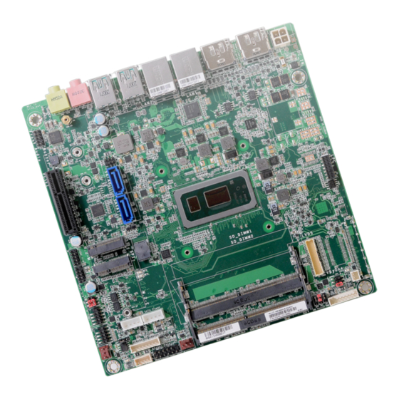
- Page 1 WL171/WL173 Mini-ITX Industrial Motherboard User’s Manual Preliminary Preliminary Version Version A-569-M-2018...
- Page 2 1. The changes or modifications not expressly approved by the party responsible for com- pliance could void the user’s authority to operate the equipment. 2. Shielded interface cables must be used in order to comply with the emission limits. User's Manual | WL171/WL173...
-
Page 3: Table Of Contents
SATA (Serial ATA) ......................19 Chassis Intrusion ......................20 Cooling Fan Connectors ....................20 Front Panel ........................21 SMBus ..........................21 Battery ..........................22 Digital I/O ........................22 LVDS Panel ........................23 V-by-One .........................24 Expansion Slots ......................25 Installing the M.2 Module .....................25 LPC ..........................26 User's Manual | WL171/WL173... - Page 4 • To reduce the risk of electric shock, unplug the power cord before removing the sys- tem chassis cover for installation or servicing. After installation or servicing, cover the system chassis before plugging the power cord. User's Manual | WL171/WL173...
- Page 5 • Storage device such as hard disk drive, CD-ROM, etc. • Power adaptor External system peripherals may also be required for navigation and display, including at least a keyboard, a mouse and a video display monitor. User's Manual | WL171/WL173...
-
Page 6: Chapter 1 - Introduction
The specifications listed here may be based on editions that do not resemble your actual products. Please visit the download page at go.dfi. com/WL17x, or via the QR code to the right for the latest datasheet. User's Manual | WL171/WL173... -
Page 7: Features
Event) signal. However, if your system is in the Suspend mode, you can power-on the system only through an IRQ or DMA interrupt. Wake-On-USB This function allows you to use a USB keyboard or USB mouse to wake up a system from the S3 (STR - Suspend To RAM) state. User's Manual | WL171/WL173... -
Page 8: Chapter 2 - Hardware Installation
Failure to do so will cause severe damage to the motherboard and compo- SATA0 LED1 M.2 E Key nents. Note: Some of the components are model-specific. Please refer to the specifications for detail. User's Manual | WL171/WL173... -
Page 9: System Memory
DIMMs. Not all slots need to be populated. Dual Channel DIMMs of the same memory configuration are on different channels. Features • 2 x 260-pin SODIMM up to 64GB • DDR4 2400MHz (Celeron 4305UE 2133MHz only) 4 5 ° Step 1 User's Manual | WL171/WL173... -
Page 10: Heatsink And Fan
Inspect that the clip sits in the notch. If not, please pull the clips outward, release and remove the Step 3 card, and mount it again. CPU fan connector Mic In Line Out User's Manual | WL171/WL173... - Page 11 4. Screw tight two of the spring screws at opposite corners into the mounting holes. And then proceed with the other two spring screws. 5. Connect the CPU fan’s cable to the CPU fan connector on the system board. User's Manual | WL171/WL173...
-
Page 12: Jumper Settings
LED3 M.2 M Key Front Panel SATA Power SPI Flash BIOS SATA1 LED2 CPU FAN DIO Power SPI Flash BIOS SATA1 LED2 CPU FAN DIO Power SATA0 LED1 M.2 E Key SATA0 LED1 M.2 E Key User's Manual | WL171/WL173... -
Page 13: Panel Power Select (Jp4)
SPI Flash BIOS SATA1 LED2 CPU FAN DIO Power SMBUS LED3 M.2 M Key Front Panel SATA Power SATA0 LED1 M.2 E Key SPI Flash BIOS SATA1 LED2 CPU FAN DIO Power User's Manual | WL171/WL173 SATA0 LED1 M.2 E Key... -
Page 14: Com1 Power Select
„ 2-4 On: Pin 1 = DCD- „ 4-6 On: Pin 1 = +12V „ 1-2 On: Via power button (default) „ 2-3 On: Via AC Power „ 1-3 On: Pin 9 = RI- „ 3-5 On: Pin 9 = +5V User's Manual | WL171/WL173... -
Page 15: Rear I/O Ports
Using a voltage higher than the recommended range may result in failure in start- ing and booting the system or causing irreversible damage to the system board. A power adaptor/converter is necessary when the power source on site does not comply with the power specifications of the board. User's Manual | WL171/WL173... -
Page 16: Usb Ports
Type A ports at the rear side. For the internal USB ports, please refer to the next section. Wake-On-USB Keyboard/Mouse The Wake-On-USB Keyboard/Mouse function allows you to use a USB keyboard or USB mouse to wake up a system from the S3 (STR - Suspend To RAM) state. User's Manual | WL171/WL173... -
Page 17: Rj45 Lan
This jack is used to connect a headphone or external speakers. • Mic-in Jack (Pink) Features This jack is used to connect an external microphone. • LAN1: Intel I219LM LAN PHY ® • LAN2: Intel I210AT PCIe Gigabit Ethernet LAN Controller ® User's Manual | WL171/WL173... -
Page 18: Internal I/O Connectors
N.C. Wake-On-USB Keyboard/Mouse The Wake-On-USB Keyboard/Mouse function allows you to use a USB keyboard or USB mouse RTS- RTS- N.C. N.C. to wake up a system from the S state(s). CTS- CTS- N.C. N.C. N.C. N.C. User's Manual | WL171/WL173... -
Page 19: Front Audio
„ Front Audio Pin Assignment Pin Assignment Pin Assignment „ SATA Pin Assignment „ SATA Power Pin Assignment Mic-L Mic-R N.C. +12V Line-Out-R Mic-JD (sense) SMBUS LED3 M.2 M K SPI Flash BIOS SATA1 LED2 Line-Out-L Line-JD (sense) SATA0 LED1 User's Manual | WL171/WL173... -
Page 20: Chassis Intrusion
„ 3-pin Fan Pin Assignment „ 4-pin Fan Pin Assignment „ Chassis Intrusion Pin Assignment Pin Assignment Pin Assignment Pin Assignment Pin Assignment Ground Ground Signal Power Power Sense Sense Speed Control User's Manual | WL171/WL173... -
Page 21: Front Panel
Power On Suspend) state, it will blink at 1-second intervals. When the system is in the S3 (STR - Suspend To RAM) state, it will blink at 4-second intervals. ATX-SW - ATX Power Switch This switch is used to power on or off the system. User's Manual | WL171/WL173... -
Page 22: Battery
• There exists explosion hazard if the battery is incorrectly installed. DIO_4 • Replace only with the same or equivalent type recommended by the manufacturer. DIO_5 • Dispose of used batteries according to local ordinances. DIO_6 DIO_7 User's Manual | WL171/WL173... -
Page 23: Lvds Panel
Pin Assignment +3.3V USB 5/6 (USB 2.0) +3.3V Panel Backlight On/Off Con- trol Panel Power Panel Inverter Brightness 12V (default)/5V Panel Power Panel Power Voltage Control COM1 Panel Power 12V (default)/5V COM2 SYS FAN User's Manual | WL171/WL173 Chassis Intrusion... -
Page 24: V-By-One
N.C. Intel BGA 1528 LVDS N.C. N.C. Front Audio Buzzer TX3+ TX3- PCIE1 (PCIe x4) 0/2.0) USB 7/8 (USB 2.0) USB 5/6 (USB 2.0) TX2+ 0/2.0) TX2- COM1 User's Manual | WL171/WL173 COM2... -
Page 25: Expansion Slots
80mm) and the M.2 E key sicket (22mm x 30mm). PCI Express x4 Slot Install PCI Express cards such as network cards or other cards that comply to the PCI Express specifications into the PCI Express x4 slot. User's Manual | WL171/WL173... -
Page 26: Lpc
The L_LAD3 Fron LAN2 card should be lying parallel to the board when it’s correctly L_LAD2 mounted. Buzz SERIRQ USB 1/2 5VSB PCIE (USB 3.0/2.0) USB 3/4 (USB 3.0/2.0) User's Manual | WL171/WL173 Mic In...
Need help?
Do you have a question about the WL171/WL173 and is the answer not in the manual?
Questions and answers