Advertisement
Quick Links
Advertisement

Related Manuals for DFI WL551-BCI-4305UE


Summary of Contents for DFI WL551-BCI-4305UE
- Page 1 WL551 3.5" SBC Motherboard User’s Manual A-598-M-2040 ver.A_-_6-1021_16-11...
- Page 2 Copyright FCC and DOC Statement on Class B This publication contains information that is protected by copyright. No part of it may be This equipment has been tested and found to comply with the limits for a Class B digital reproduced in any form or by any means or used to make any transformation/adaptation device, pursuant to Part 15 of the FCC rules.
-
Page 3: Table Of Contents
Table of Contents USB Configuration ......................38 CSM Configuration ......................38 USB Power Control ......................39 Chapter 1 - Introduction........................ 6 Network Stack Configuration..................39 Specifications ......................... 6 Chipset ..........................40 WL551..........................6 Graphics Configuration ....................40 Features ..........................7 PCH-IO Configuration ....................41 PCI Express Configuration ....................41 Chapter 2 - Hardware Installation .................... - Page 4 About this Manual Static Electricity Precautions This manual can be downloaded from the website. It is quite easy to inadvertently damage your PC, system board, components or devices even before installing them in your system unit. Static electrical discharge can damage computer The manual is subject to change and update without notice, and may be based on editions components without causing any signs of physical damage.
- Page 5 Before Using the System Board About the Package When installing the system board in a new system, you will need at least the following internal The package contains the following items. If any of these items are missing or damaged, components.
-
Page 6: Chapter 1 - Introduction
Chapter 1 INTRODUCTION Chapter 1 - Introduction INTERNAL I/O Serial 1 x RS-232/422/485 (2.00mm pitch) RS485 support auto flow control 2 x USB 2.0 (2.00mm pitch) X Specifications Display 1 x LVDS LCD Panel connector or 1 x eDP LCD panel connector 1 x LCD/Intverter Power WL551 Audio... -
Page 7: Features
Chapter 1 INTRODUCTION X Features ACPI STR Watchdog Timer The system board is designed to meet the ACPI (Advanced Configuration and Power The Watchdog Timer function allows your application to regularly “clear” the system at the set Interface) specification. ACPI has energy saving features that enables PCs to implement time interval. -
Page 8: Chapter 2 - Hardware Installation
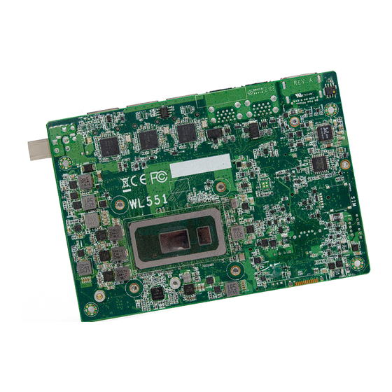
Chapter 2 HARDWARE INSTALLATION Chapter 2 - Hardware Installation Note: Some components are optional and only available upon request. X Board Layout Important: Electrostatic discharge (ESD) can damage your board, processor, disk drives, add-in boards, and other components. Perform installation procedures at an ESD workstation only. If such a station is not available, you can provide some ESD protection by wearing an antistatic wrist strap and attaching it to a metal part of the system chassis. -
Page 9: System Memory
Chapter 2 HARDWARE INSTALLATION X System Memory System Memory Installing the Memory Module Before installing the memory module, please make sure that the following safety cautions are well-attended. 1. Make sure the PC and all other peripheral devices connected to it has been powered down. -
Page 10: Removing The Memory Module
Chapter 2 HARDWARE INSTALLATION System Memory System Memory Removing the Memory Module Please follow the steps below to install the memory card into the socket. Please follow the steps below to remove the memory card from the socket. Step 1: Step 1: Press the eject tabs at both ends of the socket outward and downward to release them from the locked position. -
Page 11: Installing The Heat Sink
Chapter 2 HARDWARE INSTALLATION Installing the Heatsink or Fan Please make sure the contacting sides of the heat spreader and the module are correct — The system board may come with a heatsink or a cooler (heatsink with fan), including four the CPU side of the module shall be facing the stand-offs and four stand-off screws to secure the board and heatsink onto the chassis. -
Page 12: Jumper Settings
Chapter 2 HARDWARE INSTALLATION X Jumper Settings Jumper Settings DIO PU/PD Select (JP3) Intel Intel BGA 1528 BGA 1528 If any anomaly of the followings is encountered — To switch DIO PU/PD type. a) CMOS data is corrupted; b) you forgot the supervisor or user password; c) failure to start the system due to BIOS mis-configuration 1-3 On: DIO Power (DIO4-7) 3-5 On: GND (DIO4-7) -
Page 13: Dio Power Select (Jp2)
Chapter 2 HARDWARE INSTALLATION Jumper Settings DIO Power Select (JP2) Intel BGA 1528 JP2 is used to select the power of DIO (Digital I/O) signal. 1-2 On: 2-3 On: 5V 5VSB (default) User's Manual | WL551... -
Page 14: Panel Backlight Selection (Dpjp604)
Chapter 2 HARDWARE INSTALLATION Jumper Settings Jumper Settings Panel Backlight Selection (DPJP604) Panel Inverter Power Selection (DPJP602) Intel Intel BGA 1528 BGA 1528 DPJP604 is used to select the panel backlight power. DPJP602 is used to select the panel inverter power. 1-2 On: 2-3 On: 1-2 On:... -
Page 15: Panel Power Selection (Dpjp603)
Chapter 2 HARDWARE INSTALLATION Jumper Settings Jumper Settings Panel Power Selection (DPJP603) InnoAGE Remote Management (JP6) Intel Intel BGA 1528 BGA 1528 DPJP603 is used to select the panel power. JP6 is used to configure the InnoAGE Remote Management. InnoAGE Remote Management Assignment Assignment PC Reset... -
Page 16: Switch Settings
Chapter 2 HARDWARE INSTALLATION X Switch Settings Intel BGA 1528 SKUs M.2 E-Key M.2 B-Key M.2 M-Key SATA_5V 1-8 ON 2-7 ON 3-6 ON 4-5 ON 000G~800G +3V3SB +3V3SB +3V3SB +5VSB 1-8 OFF 2-7 OFF 3-6 OFF 4-5 OFF 900G +3.3V +3.3V +3.3V... -
Page 17: Rear I/O Ports
Chapter 2 HARDWARE INSTALLATION X Rear I/O Ports Rear I/O Ports USB Ports Rear „ USB 3.1 Gen 2 „ LAN 1 „ LAN 2 „ LAN 3 „ DP++/HDMI The rear panel I/O ports consist of the following: • 1 HDMI / DP++ port Intel •... -
Page 18: Graphics Display
Chapter 2 HARDWARE INSTALLATION Rear I/O Ports Rear I/O Ports Graphics Display Intel Intel BGA 1528 BGA 1528 „ USB 3.1 Gen 1 „ USB 3.1 Gen 1 „ LAN 1 „ LAN 2 „ LAN 3 „ LAN 1 „... -
Page 19: Usb Ports
Chapter 2 HARDWARE INSTALLATION Internal I/O Connectors USB Ports The USB device allows data exchange between your computer and a wide range of simultaneously accessible external Plug and Play peripherals. The internal USB pin headers may be connected to a card-edge bracket. Install the card-edge „... -
Page 20: Front Audio
Chapter 2 HARDWARE INSTALLATION Internal I/O Connectors Internal I/O Connectors Front Audio Digital I/O Intel Intel BGA 1528 BGA 1528 The Front Audio internal connector allows you to connect to the second line-out and mic-in The Digital I/O (DIO) connector allows for input/output signals of digital logical states defined jacks that are at the front panel of your system. -
Page 21: Power Connector
Chapter 2 HARDWARE INSTALLATION Internal I/O Connectors Internal I/O Connectors Power Connector COM1 „ 4-pin Power Connector Intel Intel BGA 1528 BGA 1528 Connect a power cord to this terminal block by inserting the wire into the block and then screw The serial ports are asynchronous communication ports with 16C550A-compatible UARTs that tight the screw on top to secure the wire in place. -
Page 22: Lvds Panel
Chapter 2 HARDWARE INSTALLATION Internal I/O Connectors „ LVDS LCD Panel LVDS Panel Pin Function Pin Function Pin Assignment LVDSA_Out3+ LVDSB_Out3+ LVDSA_Out3- LVDSB_Out3- LVDSA_Out2+ LVDSB_Out2+ „ LCD/Inverter Power LVDSA_Out2- LVDSB_Out2- LVDSA_Out1+ LVDSB_Out1+ Intel LVDSA_Out1- LVDSB_Out1- BGA 1528 LVDSA_Out0+ LVDSB_Out0+ LVDSA_Out0- LVDSB_Out0- LVDSA_CLK1+ LVDSB_CLK1+... -
Page 23: B Key 3042/2242
Chapter 2 HARDWARE INSTALLATION Internal I/O Connectors Internal I/O Connectors Expansion Slots Expansion Slots Installing the M.2 Module Before installing the M.2 module into the M.2 socket, please make sure that the following safety cautions are well-attended. 1. Make sure the PC and all other peripheral devices connected to it has been powered down. -
Page 24: Installing The Mini Pcie Module
Chapter 2 HARDWARE INSTALLATION Internal I/O Connectors Expansion Slots Internal I/O Connectors Expansion Slots Installing the Mini PCIe Module Please follow the steps below to install the card into the socket. Before installing the Mini PCIe module into the Mini PCIe socket, please make sure that the following safety cautions are well-attended. - Page 25 Chapter 2 HARDWARE INSTALLATION Internal I/O Connectors Expansion Slots Please follow the steps below to install the card into the socket. Step 1: Insert the card into the socket at an angle while making sure the notch and key are perfectly aligned. Step 2: Press the end of the card far from the socket down until against the...
-
Page 26: Front Panel
Chapter 2 HARDWARE INSTALLATION Internal I/O Connectors Front Panel PWR-LED - Power/Standby LED When the system’s power is on, this LED will light. When the system is in the S1 (POS - Power On Suspend) state, it will blink every second. When the system is in the S3 (STR - Suspend To RAM) state, it will blink every 4 seconds. -
Page 27: Battery Header
Chapter 2 HARDWARE INSTALLATION Internal I/O Connectors Internal I/O Connectors Battery Header Heater „ Heater Intel Intel BGA 1528 BGA 1528 „ Battery Header The lithium ion battery powers the real-time clock and CMOS memory. It is an auxiliary source The heater box header provides 12V power to the external heater with a 2-pin pin header for of power when the main power is shut off. -
Page 28: Smbus
Chapter 2 HARDWARE INSTALLATION Internal I/O Connectors SMBus Intel BGA 1528 The SMBus (System Management Bus) connector is used to connect the SMBus device. It is a multiple device bus that allows multiple chips to connect to the same bus and enable each one to act as a master by initiating data transfer. -
Page 29: Chapter 3 - Bios Settings
Chapter 3 BIOS SETTINGS Chapter 3 - BIOS Settings Legends X Overview Keys Function The BIOS is a program that takes care of the basic level of communication between the CPU and peripherals. It contains codes for various advanced features found in this system board. Right / Left arrow Move the highlight left or right to select a menu The BIOS allows you to configure the system and save the configuration in a battery-backed... -
Page 30: Main
Chapter 3 BIOS SETTINGS X Main X Advanced The Main menu is the first screen that you will see when you enter the BIOS Setup Utility. The Advanced menu allows you to configure your system for basic operation. Some entries are defaults required by the system board, while others, if enabled, will improve the performance of your system or let you set some features according to your preference. -
Page 31: Rc Acpi Configuration
Chapter 3 BIOS SETTINGS Advanced Advanced RC ACPI Configuration CPU Configuration Aptio Setup Utility - Copyright (C) 2019 American Megatrends, Inc. Aptio Setup Utility - Copyright (C) 2019 American Megatrends, Inc. Advanced Advanced CPU Configuration When enabled, a VMM can RC ACPI Configuration Enable or disable System utilize the additional hard-... -
Page 32: Power & Performance
Chapter 3 BIOS SETTINGS Advanced Advanced Power & Performance PCH-FW Configuration Aptio Setup Utility - Copyright (C) 2019 American Megatrends, Inc. Aptio Setup Utility - Copyright (C) 2019 American Megatrends, Inc. Advanced Advanced ME State [Enabled] When Disabled ME will be Power &... - Page 33 Chapter 3 BIOS SETTINGS Advanced PCH-FW Configuration Advanced ► Firmware Update Configuration Trusted Computing Aptio Setup Utility - Copyright (C) 2019 American Megatrends, Inc. Advanced Enables or Disables BIOS TPM20 Device Found support for security de - Firmware Version 403.1 v i c e .
- Page 34 Chapter 3 BIOS SETTINGS Advanced PTN3460 Config Aptio Setup Utility - Copyright (C) 2020 American Megatrends, Inc. Advanced PTN3460 Function [Enable] Enable or Disable PTN3460 LCD Panel Type [1920x1080] LCD Features LCD Panel Color Depth [48 Bit] Backlight Type [Normal+PWM Mode] →←: Select Screen ↑↓: Select Item Enter: Select...
-
Page 35: Trusted Computing
Chapter 3 BIOS SETTINGS Advanced Advanced NCT6116D Super IO Configuration NCT5525D Super IO Configuration ► Serial Port Configuration Aptio Setup Utility - Copyright (C) 2019 American Megatrends, Inc. Aptio Setup Utility - Copyright (C) 2019 American Megatrends, Inc. Advanced Advanced NCT5525D Super IO Configuration WatchDog Timer Unit Se- Serial Port 1 Configuration... -
Page 36: Nct5525D Hw Monitor
Chapter 3 BIOS SETTINGS Advanced Advanced NCT5525D HW Monitor NCT5525D HW Monitor ► Smart Fan Function Aptio Setup Utility - Copyright (C) 2019 American Megatrends, Inc. Aptio Setup Utility - Copyright (C) 2019 American Megatrends, Inc. Advanced Advanced Smart Fan function setting Enable CPU SmartFan Pc Health Status Smart Fan Function... -
Page 37: Serial Port Console Redirection
Chapter 3 BIOS SETTINGS Advanced Advanced Serial Port Console Redirection Serial Port Console Redirection ► Console Redirection Settings Aptio Setup Utility - Copyright (C) 2019 American Megatrends, Inc. Aptio Setup Utility - Copyright (C) 2019 American Megatrends, Inc. Advanced Advanced Console Redirection En - Enable CPU SmartFan COM1... -
Page 38: Usb Configuration
Chapter 3 BIOS SETTINGS Advanced Advanced USB Configuration CSM Configuration Aptio Setup Utility - Copyright (C) 2019 American Megatrends, Inc. Aptio Setup Utility - Copyright (C) 2019 American Megatrends, Inc. Advanced Advanced Enables Legacy USB sup- Enable/Disable CSM Sup- USB Configuration Compatibility Support Module Configuration port. -
Page 39: Usb Power Control
Chapter 3 BIOS SETTINGS Advanced Advanced USB Power Control Network Stack Configuration Aptio Setup Utility - Copyright (C) 2019 American Megatrends, Inc. Aptio Setup Utility - Copyright (C) 2019 American Megatrends, Inc. Advanced Advanced Enable/Disable CSM Sup- Enable/Disable UEFI Net- USB2_1/2 USB3_1/2 [5V_Dual] Network Stack... -
Page 40: Chipset
Chapter 3 BIOS SETTINGS X Chipset X Chipset Chipset Graphics Configuration Aptio Setup Utility - Copyright (C) 2019 American Megatrends, Inc. Aptio Setup Utility - Copyright (C) 2019 American Megatrends, Inc. Main Advanced Chipset Security Boot Save & Exit Chipset ►... -
Page 41: Pch-Io Configuration
Chapter 3 BIOS SETTINGS Chipset Chipset PCH-IO Configuration PCH-IO Configuration PCI Express Configuration Aptio Setup Utility - Copyright (C) 2019 American Megatrends, Inc. Aptio Setup Utility - Copyright (C) 2019 American Megatrends, Inc. Chipset Chipset PCI Express Configuration PCI Express Root Port Set- PCH-IO Configuration PCI Express Configuration settings... -
Page 42: Sata And Rst Configuration
Chapter 3 BIOS SETTINGS Advanced Chipset PCH-IO Configuration SATA And RST Configuration HD Audio Configuration Aptio Setup Utility - Copyright (C) 2019 American Megatrends, Inc. Aptio Setup Utility - Copyright (C) 2019 American Megatrends, Inc. Chipset Chipset SATA And RST Configuration E n a b l e o r d i s a b l e S ATA Control Detection of the HD Audio Subsystem Confi guration Settings... -
Page 43: Security
Chapter 3 BIOS SETTINGS X Security X Security Security Secure Boot Aptio Setup Utility - Copyright (C) 2019 American Megatrends, Inc. Aptio Setup Utility - Copyright (C) 2019 American Megatrends, Inc. Main Advanced Chipset Security Boot Save & Exit Security Password Description: S e t A d m i n i s t r a t o r P a s s - System Mode... - Page 44 Chapter 3 BIOS SETTINGS Security Secure Boot X Key Management • “PK” for Platform Keys Aptio Setup Utility - Copyright (C) 2019 American Megatrends, Inc. Security • “KEK” for Key Exchange Keys Factory Key Provision [Disabled] Provision factory default keys on next re-boot only •...
-
Page 45: Boot
Chapter 3 BIOS SETTINGS X Boot X Save & Exit Aptio Setup Utility - Copyright (C) 2019 American Megatrends, Inc. Aptio Setup Utility - Copyright (C) 2019 American Megatrends, Inc. Main Advanced Chipset Security Boot Save & Exit Main Advanced Chipset Security Boot... -
Page 46: Updating The Bios
BIOS with the flash utility. For updating AMI BIOS in UEFI mode, you may refer to the how-to video at https://www.dfi.com/Knowledge/Video/5. X Notice: BIOS SPI ROM 1.
Need help?
Do you have a question about the WL551-BCI-4305UE and is the answer not in the manual?
Questions and answers