Advertisement
Quick Links
Advertisement

Related Manuals for Ariesys ARP 880


Summary of Contents for Ariesys ARP 880
- Page 1 ARP 880 User Reference Manual...
-
Page 2: Specifications
Specifications Model No ARP880 Motherboard Support standard ATX Motherboard Slots Offer 7 full length expansion slots Drive bay Support 2x 5.25”, 1x 2.5” hidden, slim Display 17.3" FHD LCD display, 1920x 1080, LED backlight AD conversion board, DP interface (Option: DVI or VGA) KB/MS Industrial multi-languages Keyboard/ touchpad Keyboard Layout: CH, FR, GR, KR, RU, SP, UK, US... - Page 3 Standard Accessory Kits ARP 880 Model Accessory Kit SKD ARP880 Portable Computer Chassis ARP880 Carrying Case with wheels User’s Manual Power Cord Anti-Static Bag Screw Pack (stabilizer) Stabilizer Supports Pack Carrying Case with Wheels 3...
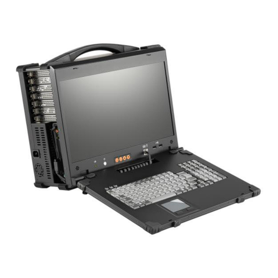
- Page 4 1.0 Introduction ARP 880 features: ● Rugged Construction with shock absorbing rubber corners ● Built-in 17.3” FHD LCD display, 1920x 1080, LED backlight ● Designed for Standard ATX Motherboard ● Offer 7 full length slots expansion capability ● Industrial multi-languages keyboard with touchpad ●...
- Page 5 2.0 Getting Started 2.0 Operation 1. Releasing Keyboard by pushing the 2 taps located on top side of the chassis to release the locking mechanism, and then pull out the keyboard. Press to release Press to release 2. You have the option of leaving the keyboard attached to the chassis or they can be release independently from the chassis by pushing the two levers inward to release the lock.
- Page 6 4. You can flip the 2 feet located underneath the chassis outward to help create an angle for the chassis for viewing comfort. Power LED light 2 feet 5. Connect the power cable outlet into the power supply unit Insert Power Cord 6.
- Page 7 7. Access the 7 full-length expansion slots on the left side of the chassis. 8. ARP880 provides 2x 5.25”, 1x 2.5” hidden, and 1x slim drive bays 1x 2.5” hidden 9. Full function keyboard and touchpad surface act as input for the system. Keyboard LED Touchpad + Button 7...
- Page 8 3.0 Internal Hardware Access Be sure power cable is not connected to the system before proceeding 1. Open Back Cover Unscrew Unscrew Unscrew Unscrew Unscrew Unscrew Unscrew Unscrew Unscrew 2. Remove the Card stabilizer bar Unscrew Unscrew Unscrew Unscrew 8...
- Page 9 3. Install the proper stand-off matching the ATX Motherboard into the chassis and correct I/O plate supplied by board manufacturer and secure the motherboard onto chassis. 9...
- Page 10 4. Install your add-in card on the available connection interface, and inserted completely and tight. 6. Remount the card stabilizer bar and put the rear cover back Screw Screw Screw Screw Screw Screw Screw Screw Screw Screw Screw Screw Screw Screw 10...
-
Page 11: Software Installation
4.0 Software Installation You can use the built-in DVD-RW to load operating system and additional applications software into the system. Available medium from USB or download can also be possible. DOS Boot up: DOS boot up requires you to have a version of the DOS installed on hard disk drive or floppy. -
Page 12: Troubleshooting
5.0 Troubleshooting 1. Installation problem: 1. Normally problem with a fail start up is due to installation problem. 2. Double check all the peripheral cards or items you have added to the ARP. 3. Are all the items seated properly? 4.
Need help?
Do you have a question about the ARP 880 and is the answer not in the manual?
Questions and answers