
Subscribe to Our Youtube Channel
Related Manuals for Lenze i410


Summary of Contents for Lenze i410
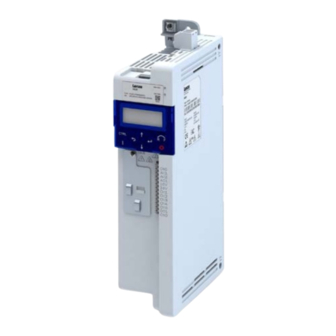
- Page 1 Operating Instructions | EN Inverter Inverter i410-Cabinet 0.25 ... 2.2 kW As easy as that.
- Page 2 Overview Overview Hardware overview of the inverter PE connec on X100 Mains connec on Relay output Inverter status LEDs Keypad Shield connec on IT screw Control connec ons Control terminals X105 Motor connec on Basic I/O Operating Instructions i410-Cabinet...
-
Page 3: Table Of Contents
8.4 LED status ........................23 5.2 EMC-compliant installation ....................9 Further documents ....................23 5.3 Control terminals ......................10 10 Disposal ........................23 5.4 Relay output ........................10 5.5 Single-phase mains connection 230/240 V ..............11 11 Glossary ........................23 6 Initial switch-on ......................12 Operating Instructions i410-Cabinet... -
Page 4: General Information
The product is designed for the installation into electrical systems or machinery. The i400 product family is designed for a power range of 0.25 ... 2.2 kW. The i410 inverter is suitable for conveyor and travelling drives, pumps, fans, winders, lifting systems and many other machine tasks. -
Page 5: Identification Of The Products
Design types Global type 50 Hz take responsibility for the suitability of the process and circuit proposals. Basic I/O without network 000S The product may cause EMC interferences. The operator is responsible for executing the interference suppression measures. Operating Instructions i410-Cabinet... -
Page 6: Layout Of Warning Notices
In the event of a short circuit of two power transistors, a residual movement of up to 180°/ Indicates a material hazard. Failure to comply with this instruction may result in material number of pole pairs on the motor may occur (e.g. 4-pole motor): residual movement max. damage. 180 °/2 = 90°). Operating Instructions i410-Cabinet... -
Page 7: Standards And Operating Conditions
40 °C and switching frequencies of 8 and 16 kHz Ambient temperature 55 °C (derating of 2.5 %/ °C above 45 °C) Max. output frequency 0 Hz ... 599 Hz Overload capacity 200 % for 3s; 150 % for 60 s (230/240 V mains supply) TX10 Operating Instructions i410-Cabinet... -
Page 8: Mechanical Installation
0.25 – 0.37 0.75 I41AExxxB 0.75 0.95 I41AExxxB 1.1 – 2.2 1.35 Device height Number of top/bottom fixings Device width (lower fastening not visible) Device depth Top mounting clearance Hole dimension for top/bottom fixing Bottom mounting clearance Operating Instructions i410-Cabinet... -
Page 9: Electrical Installation
AC 240 V < 75/150 pF/m ≤ 2.5 mm²; C-core/core/C-core/shield Basic I/O < 150/300 pF/m ≥ 4 mm²) +24 V +10 V 100 mA Alternatively, the motor cable can be shielded on an optional motor shield plate. " " Operating Instructions i410-Cabinet... -
Page 10: Control Terminals
0.25 ... 2.2 AC 240 V/3 A Connection Control terminal X3 DC 24 V/2 A Connection type Plug-in spring terminal DC 240 V/0.16 A Max. cable cross-section mm² Stripping length Tightening torque Tools required 0.4 x 2.5 Control terminals Operating Instructions i410-Cabinet... -
Page 11: Single-Phase Mains Connection 230/240 V
45 Hz ... 65 Hz Rated motor current Max. current [15 s] 10.5 14.4 Operation without mains choke Fuse Motor connection Characteristic gG/gL or gRL Max. rated current Circuit breaker Characteristic Max. rated current Earth-leakage circuit breaker 1-phase mains connection ≥ 30 mA, type B Operating Instructions i410-Cabinet... -
Page 12: Commissioning
• The analog input X3/AI1 must not be wired or connected to GND. Switch on mains voltage ► Switch on mains voltage and check readiness for operation. Observe LED status displays “RDY” and “ERR” on the inverter front panel. See “LED status”. Operating Instructions i410-Cabinet... -
Page 13: Keypad Module
3 s to save the settings permanently. 7.1.2 Example of the keypad handling Example for DO1 function assignment with parameter P420.02. P430.02 P430.02 I/O setting P210.00 GROUP 4 Time Fct. dig. outputs P420.XX DO1 func on P420.02 Operating Instructions i410-Cabinet... -
Page 14: Extended Terminal Control
DO1 activated at Digital output 1 *P420.02 Commissioning & diagnostics can also be carried out using the Lenze EasyStarter tool. Release brake GND for analog and digital signals This requires a USB module and a standard USB cable (A plug to Micro-B plug). -
Page 15: The Most Important Parameters At A Glance
Commissioning The most important parameters at a glance This chapter contains the most important parameters and selections. You can find a detailed description in the commissioning document. http://www.Lenze.com The parameters are divided into the following function groups: • Pxxx.xx group 0: Favorites •... - Page 16 Assignment of a trigger to the “inverter enable“ function. Trigger = TRUE: The inverter is enabled (unless there is another cause for inverter disable). Trigger = FALSE: The inverter is disabled. The motor has no torque and coasts. Default setting = bold print | * Default setting is device-dependent Operating Instructions i410-Cabinet...
- Page 17 Assignment of a trigger to the “Activate preset (bit 0)” function. Bit with the value 2 for the bit-coded selection and activation of a configured setpoint (preset value). Trigger = FALSE: Bit = “0”. Trigger = TRUE: Bit = “1”. Default setting = bold print | * Default setting is device-dependent Operating Instructions i410-Cabinet...
- Page 18 Actual frequency setpoint (resolution: 0.1 Hz). Analog input 1 Input signal from analog input 1 (resolution: 0.1 %). P440.03 AO1 min. Signal Definition of the signal value that corresponds to the minimum value at analog output 1. Default setting = bold print | * Default setting is device-dependent Operating Instructions i410-Cabinet...
-
Page 19: Group 2: Basic Setting
• This process may take some seconds. When the device command has been executed successfully, the value 0 is shown. • Loading parameters has a direct effect on cyclic communication: The data exchange for control is interrupted and a communication error is generated. Operating Instructions i410-Cabinet... -
Page 20: Troubleshooting
2. Via P400.04 (default setting of digital input 2). • Cause of error has been eliminated and no blocking time is active. • The error is reset if a signal is applied to digital input 2 (P400.04). Operating Instructions i410-Cabinet... -
Page 21: Error Codes
• Check mains settings. 4210 PU: Overtemperature fault Error • Check mains voltage. • Ensure sufficient cooling of the device (heatsink temperature displayed in P117.01). • Clean fan and ventilation slots. Replace fan if necessary. • Reduce switching frequency (P305.00). Operating Instructions i410-Cabinet... - Page 22 • Adapt the maximum motor speed (P322.00) and the warning threshold or error threshold (P350.01). FF37 Automatic start disabled Error • Deactivate start command and reset error. FF85 Keypad full control active Warning • Press the keypad key to exit control mode. CTRL Operating Instructions i410-Cabinet...
-
Page 23: Led Status
Fundamental information on project planning and ordering the product Commissioning document Fundamental information for the installation and commissioning of the pro- duct Mounting instructions Fundamental information on mounting the product The documents can be found in the Lenze Doc Finder. Operating Instructions i410-Cabinet... - Page 24 © 01/2020 | 2.0 Lenze Drives GmbH P.O. box 10 13 52, 31763 Hameln Breslauer Strasse 3, 32699 Extertal GERMANY HR Lemgo B 6478 Tel.: +49 5154 82-0 Fax: +49 5154 82-2800 E-Mail: sales.de@lenze.com Web: www.Lenze.com Lenze Service GmbH Breslauer Strasse 3, 32699 Extertal GERMANY Tel.: 0080002446877 (24-h helpline)
Need help?
Do you have a question about the i410 and is the answer not in the manual?
Questions and answers