Table of Contents
Advertisement
Quick Links
A l l t e s t I n s t r u me n t s , I n c .
5 0 0 C e n t r a l A v e .
F a r mi n g d a l e , N J 0 7 7 2 7
P : ( 7 3 2 ) 9 1 9 - 3 3 3 9
F : ( 7 3 2 ) 9 1 9 - 3 3 3 2
a l l t e s t . n e t
s s a l e s @ a l l t e s t . n e t
T h e t e s t & me a s u r e me n t
e q u i p me n t y o u n e e d a t
t h e p r i c e y o u w a n t .
A l l t e s t c a r r i e s t h e w o r l d ' s l a r g e s t s e l e c t i o n o f
u s e d / r e f u r b i s h e d b e n c h t o p t e s t & me a s u r e me n t
e q u i p me n t a t 5 0 % t h e p r i c e o f n e w .
O O u r e q u i p me n t i s g u a r a n t e e d w o r k i n g , w a r r a n t i e d , a n d
a v a i l a b l e w i t h c e r t i f i e d c a l i b r a t i o n f r o m o u r i n - h o u s e s t a f f
o f t e c h n i c i a n s a n d e n g i n e e r s .
• 1 0 + f u l l t i me t e c h n i c i a n s w i t h o v e r 1 5 0 y e a r s o f
s p e c i a l i z a t i o n
• 9 0 d a y w a r r a n t y & 5 d a y r i g h t o f r e t u r n o n a l l
e q u i p me n t
• • 1 - 3 y e a r w a r r a n t i e s f o r n e w a n d
p r e mi u m- r e f u r b i s h e d e q u i p me n t
• E v e r y u n i t t e s t e d t o O E M s p e c i f i c a t i o n s
• S a t i s f a c t i o n g u a r a n t e e d
Y o u h a v e p l a n s , w e w i l l h e l p y o u a c h i e v e t h e m.
A n y p r o j e c t . A n y b u d g e t .
t
G e t a q u o t e t o d a y !
C C a l l ( 7 3 2 ) 9 1 9 - 3 3 3 9 o r e ma i l s a l e s @a l l t e s t . n e t .
Advertisement
Table of Contents

Related Manuals for Rohde & Schwarz R&S DVM120


Summary of Contents for Rohde & Schwarz R&S DVM120
- Page 1 T h e t e s t & me a s u r e me n t e q u i p me n t y o u n e e d a t t h e p r i c e y o u w a n t . A l l t e s t I n s t r u me n t s , I n c .
- Page 2 R&S DVM120/400 ® Digital Video Measurement System Quick Start Guide 2085.1839.62 – 08...
- Page 3 ® The Quick Start Guide describes the following R&S DVM120/400 models and options: ® - R&S DVM120 2085.1700.03 ® - R&S DVM400 2085.1800.03 This library makes uses of techniques from MPEG. License notice: THIS PRODUCT IS LICENSED UNDER THE AVC PATENT PORTFOLIO LICENSE FOR THE PERSONAL AND NON COMMERCIAL USE OF A CONSUMER TO (i) ENCODE VIDEO IN COMPLIANCE WITH THE AVC STANDARD ("AVC VIDEO") AND/OR (ii) DECODE AVC VIDEO THAT WAS ENCODED BY A CONSUMER ENGAGED IN A PERSONAL AND NON COMMERCIAL ACTIVITY...
- Page 4 Basic Safety Instructions Always read through and comply with the following safety instructions! All plants and locations of the Rohde & Schwarz group of companies make every effort to keep the safety standards of our products up to date and to offer our customers the highest possible degree of safety.
- Page 5 Basic Safety Instructions systems and all accessories. For product-specific information, see the data sheet and the product documentation. Symbols and safety labels Symbol Meaning Symbol Meaning Notice, general danger location ON/OFF supply voltage Observe product documentation Caution when handling heavy Standby indication equipment Danger of electric shock...
- Page 6 Basic Safety Instructions Signal words and their meaning The following signal words are used in the product documentation in order to warn the reader about risks and dangers. Indicates an imminently hazardous situation which, if not avoided, will result in death or serious injury. Indicates a potentially hazardous situation which, if not avoided, could result in death or serious injury.
- Page 7 Basic Safety Instructions 2. Do not place the product on surfaces, vehicles, cabinets or tables that for reasons of weight or stability are unsuitable for this purpose. Always follow the manufacturer's installation instructions when installing the product and fastening it to objects or structures (e.g. walls and shelves). An installation that is not carried out as described in the product documentation could result in personal injury or even death.
- Page 8 Basic Safety Instructions 5. Never use the product if the power cable is damaged. Check the power cables on a regular basis to ensure that they are in proper operating condition. By taking appropriate safety measures and carefully laying the power cable, ensure that the cable cannot be damaged and that no one can be hurt by, for example, tripping over the cable or suffering an electric shock.
- Page 9 Basic Safety Instructions 16. Unless specified otherwise, products are not liquid-proof (see also section "Operating states and operating positions", item 1). Therefore, the equipment must be protected against penetration by liquids. If the necessary precautions are not taken, the user may suffer electric shock or the product itself may be damaged, which can also lead to personal injury.
- Page 10 Basic Safety Instructions 6. Should a fire occur, the product may release hazardous substances (gases, fluids, etc.) that can cause health problems. Therefore, suitable measures must be taken, e.g. protective masks and protective clothing must be worn. 7. Laser products are given warning labels that are standardized according to their laser class.
- Page 11 Basic Safety Instructions 1. Cells must not be taken apart or crushed. 2. Cells or batteries must not be exposed to heat or fire. Storage in direct sunlight must be avoided. Keep cells and batteries clean and dry. Clean soiled connectors using a dry, clean cloth.
- Page 12 Basic Safety Instructions 3. If you use the product in a vehicle, it is the sole responsibility of the driver to drive the vehicle safely and properly. The manufacturer assumes no responsibility for accidents or collisions. Never use the product in a moving vehicle if doing so could distract the driver of the vehicle.
- Page 13 Instrucciones de seguridad elementales ¡Es imprescindible leer y cumplir las siguientes instrucciones e informaciones de seguridad! El principio del grupo de empresas Rohde & Schwarz consiste en tener nuestros productos siempre al día con los estándares de seguridad y de ofrecer a nuestros clientes el máximo grado de seguridad.
- Page 14 Instrucciones de seguridad elementales Tener en cuenta las informaciones de seguridad sirve para evitar en lo posible lesiones o daños por peligros de toda clase. Por eso es imprescindible leer detalladamente y comprender por completo las siguientes informaciones de seguridad antes de usar el producto, y respetarlas durante el uso del producto. Deberán tenerse en cuenta todas las demás informaciones de seguridad, como p.
- Page 15 Instrucciones de seguridad elementales Símbolo Significado Símbolo Significado Aviso: Cuidado en el manejo de Distintivo de la UE para la dispositivos sensibles a la eliminación por separado de electrostática (ESD) dispositivos eléctricos y electrónicos Más información en la sección "Eliminación/protección del medio ambiente", punto 2.
- Page 16 Instrucciones de seguridad elementales Estados operativos y posiciones de funcionamiento El producto solamente debe ser utilizado según lo indicado por el fabricante respecto a los estados operativos y posiciones de funcionamiento sin que se obstruya la ventilación. Si no se siguen las indicaciones del fabricante, pueden producirse choques eléctricos, incendios y/o lesiones graves con posible consecuencia de muerte.
- Page 17 Instrucciones de seguridad elementales 2. Los productos de la clase de protección I con alimentación móvil y enchufe individual solamente podrán enchufarse a tomas de corriente con contacto de seguridad y con conductor de protección conectado. 3. Queda prohibida la interrupción intencionada del conductor de protección, tanto en la toma de corriente como en el mismo producto.
- Page 18 Instrucciones de seguridad elementales 10. Para la conexión con dispositivos informáticos como un PC o un ordenador industrial, debe comprobarse que éstos cumplan los estándares IEC60950- 1/EN60950-1 o IEC61010-1/EN 61010-1 válidos en cada caso. 11. A menos que esté permitido expresamente, no retire nunca la tapa ni componentes de la carcasa mientras el producto esté...
- Page 19 Instrucciones de seguridad elementales Funcionamiento 1. El uso del producto requiere instrucciones especiales y una alta concentración durante el manejo. Debe asegurarse que las personas que manejen el producto estén a la altura de los requerimientos necesarios en cuanto a aptitudes físicas, psíquicas y emocionales, ya que de otra manera no se pueden excluir lesiones o daños de objetos.
- Page 20 Instrucciones de seguridad elementales 7. Los productos con láser están provistos de indicaciones de advertencia normalizadas en función de la clase de láser del que se trate. Los rayos láser pueden provocar daños de tipo biológico a causa de las propiedades de su radiación y debido a su concentración extrema de potencia electromagnética.
- Page 21 Instrucciones de seguridad elementales 1. No deben desmontarse, abrirse ni triturarse las celdas. 2. Las celdas o baterías no deben someterse a calor ni fuego. Debe evitarse el almacenamiento a la luz directa del sol. Las celdas y baterías deben mantenerse limpias y secas.
- Page 22 Instrucciones de seguridad elementales 3. Si se utiliza el producto dentro de un vehículo, recae de manera exclusiva en el conductor la responsabilidad de conducir el vehículo de manera segura y adecuada. El fabricante no asumirá ninguna responsabilidad por accidentes o colisiones.
- Page 23 Safety Instructions - Informaciones de seguridad Safety Instructions for Instruments with Fold-Out Feet Danger of injury The feet may fold in if they are not folded out completely or if the in- strument is shifted. The feet may break if they are overloaded. Fold the feet completely in or completely out to ensure stability of the instrument and personal safety.
- Page 24 Safety Instructions - Informaciones de seguridad Informaciones de seguridad para aparatos con telepiés Peligro de heridas Los telepiés pueden doblarse hacia adentro si no han sido desdobla- dos por completo o si el aparato es movido. Los telepiés pueden rom- perse si son sobrecargados.
- Page 25 Safety Instructions - Informaciones de seguridad Safety Instructions for Stacking Instruments Danger of injury Instruments may slip if they are stacked on top of each other. Place the instrument on a stable, even surface. Stack the instruments according to their size, with the largest instrument on the bottom. Do not stack more than three in-struments directly on top of each other.
- Page 26 Safety Instructions - Informaciones de seguridad Informaciones de seguridad para el amontonamiento de aparatos Peligro de heridas Los aparatos pueden desplazarse al ser amontonados. Posicionar los aparatos sobre una superficie estable y lisa. Amontonar los aparatos por orden de su tamaño. No amontonar nunca más de tres aparatos uno sobre el otro.
- Page 27 Customer Support Technical support – where and when you need it For quick, expert help with any Rohde & Schwarz equipment, contact one of our Customer Support Centers. A team of highly qualified engineers provides telephone support and will work with you to find a solution to your query on any aspect of the operation, programming or applications of Rohde &...
- Page 28 Qualitätszertifikat Certifi ed Quality System ISO 9001 Certificate of quality Certifi ed Environmental System ISO 14001 Certificat de qualité Sehr geehrter Kunde, Dear customer, Cher client, Sie haben sich für den Kauf eines You have decided to buy a Vous avez choisi d’acheter un Rohde &...
- Page 29 이 기기는 업무용(A급) 전자파 적합기기로서 판매자 또는 사용자는 이 점을 주의하시기 바라며, 가정외의 지역에서 사용하는 것을 목적으로 합니다.
- Page 30 EC Certificate of Conformity Certificate No.: 2007-08 This is to certify that: Equipment type Stock No. Designation DVM50 2085.1900.03 MPEG2 Monitoring System DVM100 2085.1600.03 DVM120 2085.1700.03 DVM-B1 2085.3283.02 Analyzer Board DVM-B53 2085.5657.02 DVB-T / DVB-H Receiver Module DVM-B520 2085.5640.02 Integration Set for DVM-B52 complies with the provisions of the Directive of the Council of the European Union on the approximation of the laws of the Member States - relating to electrical equipment for use within defined voltage limits...
- Page 31 EC Certificate of Conformity Certificate No.: 2007-07 This is to certify that: Equipment type Stock No. Designation DVM400 2085.1800.03 Digital Video Measurement System DVM-B50 2085.5605.02 Demodulator Module DVM-B51 2085.5611.02 DVB-S / DVB-S2 Receiver Module DVM-B52 2085.5628.02 DVB-T / DVB-H Receiver Module DVM400-B1 2085.5505.02 Analyzer...
- Page 32 EC Certificate of Conformity Certificate No.: 2007-50 This is to certify that: Equipment type Stock No. Designation DVM-B30 2085.5570.02 Video and Audio Hardware Decoder DVM-B50 2085.5605.02 Demodulator Module DVM-B51 2085.5611.02 DVB-S / DVB-S2 Receiver Module DVM-B52 2085.5628.02 DVB-T / DVB-H Receiver Module DVM-B500 2085.5634.02 RF Carrier Board...
-
Page 33: Table Of Contents
R&S DVM120/400 Table of Contents Table of Contents 1 Putting into Operation ............1.1 1.1 Notes on Putting into Operation ............. 1.1 1.1.1 Unpacking the Instrument ................1.1 1.1.2 Positioning the Instrument................1.2 1.1.3 AC Supply ....................1.2 1.1.4 EMC Safety Precautions ................1.2 1.1.5 Fuses ...................... - Page 34 R&S DVM120/400 Table of Contents 2.4.7 Firmware Update..................2.21 2.4.8 Recovery and Backup Partition ..............2.22 2.4 Launching the R&S DVM Analyzer Application and Creating a Basic Configuration..................2.33 2.4.1 Launching the R&S DVM Analyzer Application ........2.33 2.4.2 Creating a Basic Configuration..............2.33 2.4.3 The R&S DVM Measurement Screen and its Operating Elements ..
- Page 35 R&S DVM50/100L/120/400 Documentation Overview Documentation Overview The user documentation for the R&S <Product type> is divided as follows: Quick Start Guide The printed Quick Start Guide is delivered with the R&S DVM. On CD-ROM, the Quick Start Guide is part of the manual provided in the PDF format. The Quick Start Guide contains the following information: 3 Chapter 1 This chapter contains all information about putting the instrument into operation...
- Page 36 R&S DVM50/100L/120/400 Documentation Overview Online Help The Online Help is available on the R&S DVM and is called by means of the HELP hardkey. It includes all information provided by the Quick Start Guide and the Operating Manual. For detailed information on using the Online Help refer to Chapter "Manual Operation"...
-
Page 37: Putting Into Operation
R&S DVM120/400 Putting into Operation Notes on Putting into Operation Putting into Operation Notes on Putting into Operation Prior to putting the instrument into operation, check the following: ( The instrument cover is in place and screwed on. ( Vent holes are not obstructed. ( The signal levels at the inputs do not exceed permissible limits. -
Page 38: Positioning The Instrument
R&S DVM120/400 Putting into Operation Notes on Putting into Operation 1.1.2 Positioning the Instrument For use in the lab or on a workbench, fold out the feet at the bottom of the unit. Risk of injuries Before positioning the instrument, read the safety instructions for instruments with fold- out feet at the beginning of this manual carefully. -
Page 39: Fuses
R&S DVM120/400 Putting into Operation Notes on Putting into Operation 1.1.5 Fuses The AC input of the instrument is protected by two fuses (see type label). The fuses are located next to the main switch at the rear of the instrument. Fuses Figure 1-1: 100…240 V... -
Page 40: Installation In A 19" Rack
R&S DVM120/400 Putting into Operation Notes on Putting into Operation 1.1.6 Installation in a 19" Rack When the instrument is installed in a rack, make sure that the vents for air intake in the front and side panels and the air outlets at the instrument rear are not obstructed. To mount the unit in a rack, remove the blue foot pads from the grey plastic part. -
Page 41: Switching The Instrument On And Off
R&S DVM120/400 Putting into Operation Switching the Instrument On and Off Switching the Instrument On and Off Switching on: A Set switch to position I; the instrument is ready for operation. Switching off: A Set switch to position 0. 1.2.1 Switch-On State When the instrument is switched on, the status set when the instrument was previously switched off is automatically restored. -
Page 42: Introduction To The R&S Dvm Basic System
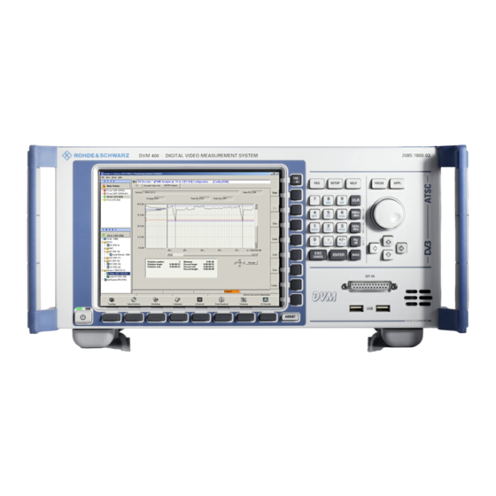
R&S DVM120/400 Introduction to the R&S DVM Basic System Legend for Front and Rear View Introduction to the R&S DVM Basic System This chapter introduces the operating concept and describes front and rear panels of the instrument with relevant control elements and connectors. Legend for Front and Rear View 2.1.1 Front Panel of the R&S DVM400... - Page 43 R&S DVM120/400 Introduction to the R&S DVM Basic System Legend for Front and Rear View ASSIST key Context-menu button opens a context-sensitive submenu for the selected element (if available). Menu buttons The menu buttons open the respective menu for the (ALT-F, ALT-S, ALT-H) application.
-
Page 44: Rear Panel Of The R&S Dvm400
R&S DVM120/400 Introduction to the R&S DVM Basic System Legend for Front and Rear View 2.1.2 Rear Panel of the R&S DVM400 Figure 2-2: Rear panel of the R&S DVM 400 Controller interfaces LAN 100 BASE-T RJ-45 female connector for remote control of the entire system via the network Note: 1000BT for R&S DVM400 Version 03 LOCAL 100 BASE-T RJ-45 female connector... - Page 45 R&S DVM120/400 Introduction to the R&S DVM Basic System Legend for Front and Rear View ANALYZER 100 BASE-T RJ-45 female connector of controller for connecting one or more analyzers via a local private network. USB interface For R&S DVM400 version 02: USB 1.0 For R&S DVM400 version 03: Top USB 1.0;...
- Page 46 R&S DVM120/400 Introduction to the R&S DVM Basic System Legend for Front and Rear View ALARM LINES 15-contact female connector 12 relay outputs that can be assigned to one or more (ORed) events. For the pin assignment, see Chapter 6. 10 MHz REF IN 10 MHz reference input TS SPI OUT...
- Page 47 R&S DVM120/400 Introduction to the R&S DVM Basic System Legend for Front and Rear View CCVS OUT (R&S DVM400-B30 option) BNC female connector Analog video output (composite) For details, see Chapter 6. HDMI / DVI-I OUT (R&S DVM400-B30 option) DVI-I female connector Digital and analog video output (components) For details, see Chapter 6.
- Page 48 R&S DVM120/400 Introduction to the R&S DVM Basic System Legend for Front and Rear View Signal connectors The signal connectors are located on the left side of the instrument. Depending on the instrument configuration, different connectors are provided. The figures below show two typical configurations of the R&S DVM400.
- Page 49 R&S DVM120/400 Introduction to the R&S DVM Basic System Legend for Front and Rear View 400-B500 RF interface option with the B50, B51, and B52 Figure 2-4: Interfaces of the R&S DVM options RF Inputs 1 to 4 (1) Signal input QPSK/8PSK (DVB-S/S2) Option R&S DVM400 F-Connector, male, 75 (2) Signal input QAM (J.83/A/B/C;...
- Page 50 R&S DVM120/400 Introduction to the R&S DVM Basic System Legend for Front and Rear View 400-B1 TS analyzer option Figure 2-5: Interfaces of the R&S DVM DVB COMMON INTERFACE Ready for future applications SDI OUT HDSDI/SDI output for R&S DVM400 B30 hardware decoder option with R&S DVM400 K30 expansion, BNC connector, female...
- Page 51 R&S DVM120/400 Introduction to the R&S DVM Basic System Legend for Front and Rear View 400-B2 TS recorder/generator option Figure 2-6: Interfaces of the R&S DVM ASI/SMPTE OUT OUT 1 and 2 TS ASI/SMPTE 310M output ASI/SMPTE IN and LOOP OUT IN 1: TS ASI/SMPTE 310M input 1 for recording LOOP OUT 1: TS ASI/SMPTE 310M active loop-through from IN 1 IN 2: TS ASI/SMPTE 310M input 2 for recording...
- Page 52 R&S DVM120/400 Introduction to the R&S DVM Basic System Legend for Front and Rear View 400-B40 Gigabit Ethernet interface option Figure 2-7: Interfaces of the R&S DVM 1000BT Gigabit Ethernet interface RJ45 connector, protocol in line with IEE 802.3 TS ASI IN/OUT (1) TS ASI output for primary IP to TS transcoding (2) TS ASI input/output for TS to IP and secondary IP to ASI transcoding.
-
Page 53: Front Panel Of The R&S Dvm120
R&S DVM120/400 Introduction to the R&S DVM Basic System Legend for Front and Rear View 2.1.3 Front Panel of the R&S DVM120 Figure 2-8: Front panel of the R&S DVM120 ANALYZER 1 ANALYZER 2 The LEDs of the two analyzers are identical to those of the R&S DVM100 analyzer (see above). - Page 54 R&S DVM120/400 Introduction to the R&S DVM Basic System Legend for Front and Rear View Figure 2-9: Analyzer TS1/TS2/TS3/TS4 Signal status of inputs 1 to 4 I ALARM off: no alarm red: no transport stream or alarm signal present yellow: an alarm signal was detected but is no longer active I SYNC green: transport stream present off: no transport stream...
-
Page 55: Rear Panel Of The R&S Dvm120
R&S DVM120/400 Introduction to the R&S DVM Basic System Legend for Front and Rear View 2.1.4 Rear Panel of the R&S DVM120 Figure 2-10: Rear panel of the R&S DVM120 Analyzer 2 or RF Analyzer 1 Interfaces Interfaces Analyzer 1 and 2 Interfaces TS ASI /SMPTE 310M (1) TS input / loop-through output (2) TS input / loop-through output... - Page 56 R&S DVM120/400 Introduction to the R&S DVM Basic System Legend for Front and Rear View RF signal interfaces 1 to 4 In the case of instruments that have an RF interface, the RF inputs replace the analyzer 2 TS interfaces. I BNC male connector for R&S DVM-B50 (DVB-C, J83.A/B, ATSC) and R&S DVM-B52 (DVB-T) I Female connector for R&S DVM-B51...
-
Page 57: Setting Up And Configuring A New R&S Dvm Analysis System
R&S DVM120/400 Introduction to the R&S DVM Basic System Setting Up and Configuring a New R&S DVM Analysis System Setting Up and Configuring a New R&S DVM Analysis System The base component of an R&S DVM Analysis System is the R&S DVM400. It contains a controller and an analyzer for monitoring up to 4 transport streams. -
Page 58: System With The R&S Dvm400
R&S DVM120/400 Introduction to the R&S DVM Basic System Setting Up and Configuring a New R&S DVM Analysis System 2.2.1 System with the R&S DVM400 If a system contains only one R&S DVM400, the analyzer can be directly connected to the controller. -
Page 59: System With The R&S Dvm400 And R&S Dvm120
R&S DVM120/400 Introduction to the R&S DVM Basic System Setting Up and Configuring a New R&S DVM Analysis System 2.2.2 System with the R&S DVM400 and R&S DVM120 In a system containing both the R&S DVM400 and R&S DVM120, the analyzers are connected to the controller via an Ethernet hub. -
Page 60: Notes On The Operating System And Firmware Update
R&S DVM50/100L/120/400 Introduction to the R&S DVM Basic System Notes on the Operating System and Firmware Update Notes on the Operating System and Firmware Update 2.3.1 Installation of the Software Only software authorized by Rohde & Schwarz for use in the R&S DVM may be installed. -
Page 61: Setting The System Time
R&S DVM50/100L/120/400 Introduction to the R&S DVM Basic System Notes on the Operating System and Firmware Update 2.3.3 Setting the System Time You can set the system time using the Windows Desktop. Setting the time of day: 1. Open the Windows XP dialog selecting "Start"... -
Page 62: Linking The System Time To An External Time Server
R&S DVM50/100L/120/400 Introduction to the R&S DVM Basic System Notes on the Operating System and Firmware Update 2.3.5 Linking the System Time to an External Time Server Switch off the XP write protection before making a change! It is possible to link the system time to an external time server of an IP network. To do this, you need to enter its IP address in the C:\Windows\ntp.conf file and declare it as “prefer”. -
Page 63: Configuring An External Keyboard
R&S DVM50/100L/120/400 Introduction to the R&S DVM Basic System Notes on the Operating System and Firmware Update 2.3.6 Configuring an External Keyboard Switch off the XP write protection before making a change! If so desired, you can connect an external keyboard to the USB interface. When delivered, the R&S DVM is preconfigured for an English US keyboard. -
Page 64: Firmware Update
R&S DVM50/100L/120/400 Introduction to the R&S DVM Basic System Notes on the Operating System and Firmware Update 2.3.7 Firmware Update Switch off the XP write protection before making a change! For step-by-step instructions how to install a new R&S DVM firmware, refer to the release notes. -
Page 65: Recovery And Backup Partition
R&S DVM50/100L/120/400 Introduction to the R&S DVM Basic System Notes on the Operating System and Firmware Update 2.3.8 Recovery and Backup Partition R&S DVM provides a backup and recovery partition. A backup of the factory system partition (C:\) is stored per default and can be recovered in case of a system crash. In addition, backups of up to 5 images of partition C: can be stored. - Page 66 R&S DVM50/100L/120/400 Introduction to the R&S DVM Basic System Notes on the Operating System and Firmware Update 3. Boot into the BIOS settings by pressing the DEL key of the external keyboard in the early boot phase when prompted at the bottom of the screen. 4.
- Page 67 R&S DVM50/100L/120/400 Introduction to the R&S DVM Basic System Notes on the Operating System and Firmware Update 5. In "Integrated Peripherals", change the "Watch Dog Timer Select" setting to "Disabled". 6. Return to the main page and select "Save & Exit Setup" to store the changes and proceed with the system boot.
- Page 68 R&S DVM50/100L/120/400 Introduction to the R&S DVM Basic System Notes on the Operating System and Firmware Update 2.3.8.2 Displaying the Windows XP Recovery and Backup Partition Dialog Before you perform a backup or recovery, make sure that the hardware watchdog is disabled. For details see chapter 2.3.8.1. 1.
- Page 69 R&S DVM50/100L/120/400 Introduction to the R&S DVM Basic System Notes on the Operating System and Firmware Update To continue see one of the following chapters: 3 Backing Up the Current System Partition (chapter 2.3.8.3) 3 Recovering the Selected Version of System Partition (chapter 2.3.8.4) 3 Recovering the Factory Default (chapter 2.3.8.5) 3 Deleting Backups (chapter 2.3.8.6) In the Windows XP Embedded Recovery and Backup Partition dialog...
- Page 70 R&S DVM50/100L/120/400 Introduction to the R&S DVM Basic System Notes on the Operating System and Firmware Update 2.3.8.3 Backing Up the Current System Partition 1. Make sure that the hardware watchdog is disabled. For details see chapter 2.3.8.1. 2. In the "Windows XP Embedded Recovery and Backup Partition" dialog, click "Make Backup".
- Page 71 R&S DVM50/100L/120/400 Introduction to the R&S DVM Basic System Notes on the Operating System and Firmware Update 2.3.8.4 Recovering the Selected Version of System Partition 1. Make sure that the hardware watchdog is disabled. For details see chapter 2.3.8.1. 2. In the "Windows XP Embedded Recovery and Backup Partition" dialog, click "Restore Backup"...
- Page 72 R&S DVM50/100L/120/400 Introduction to the R&S DVM Basic System Notes on the Operating System and Firmware Update 2.3.8.5 Recovering the Factory Default 1. Make sure that the hardware watchdog is disabled. For details see chapter 2.3.8.1. 2. In the "Windows XP Embedded Recovery and Backup Partition" dialog, click "Factory Default"...
- Page 73 R&S DVM50/100L/120/400 Introduction to the R&S DVM Basic System Notes on the Operating System and Firmware Update 2.3.8.6 Deleting Backups On the recovery partition, you can store up to five backups in addition to the factory default. To provide space for new backups, you may need to remove older backups. The factory default cannot be deleted.
-
Page 74: Launching The R&S Dvm Analyzer Application And Creating A Basic Configuration
R&S DVM50/100L/120/400 Introduction to the R&S DVM Basic System Launching the R&S DVM Analyzer Application and Creating a Basic Configuration Launching the R&S DVM Analyzer Application and Creating a Basic Configuration 2.4.1 Launching the R&S DVM Analyzer Application After power-up, the R&S DVM application is launched automatically. / If the application was terminated manually, it can be restarted any time by double- clicking the R&S DVM program icon on the desktop. -
Page 75: The R&S Dvm Measurement Screen And Its Operating Elements
R&S DVM50/100L/120/400 Introduction to the R&S DVM Basic System Launching the R&S DVM Analyzer Application and Creating a Basic Configuration Figure 2.4-1: Site tree for an R&S DVM100/DVM120 system with an analysis board having two inputs After successful configuration, all installed TS inputs are displayed in the site tree. The system is now ready for operation. - Page 76 R&S DVM50/100L/120/400 Introduction to the R&S DVM Basic System Launching the R&S DVM Analyzer Application and Creating a Basic Configuration Table 2.4-1: Elements on the R&S DVM measurement screen Element Description Taskbar Menus for control and configuration of complete system File –...
-
Page 77: Indication Of Signal And Error States
R&S DVM50/100L/120/400 Introduction to the R&S DVM Basic System Launching the R&S DVM Analyzer Application and Creating a Basic Configuration 2.4.4 Indication of Signal and Error States A key feature of the R&S DVM is the indication of signal and error states of the applied transport streams. - Page 78 R&S DVM50/100L/120/400 Introduction to the R&S DVM Basic System Launching the R&S DVM Analyzer Application and Creating a Basic Configuration Examples Table 2.4-3: Symbols for indicating alarm and error states in folders Symbol Description Status Closed folder No alarm, warning or info message is present for the contained elements.
-
Page 79: The R&S Dvm Measurement Groups
R&S DVM50/100L/120/400 Introduction to the R&S DVM Basic System Launching the R&S DVM Analyzer Application and Creating a Basic Configuration 2.4.5 The R&S DVM Measurement Groups The following R&S DVM measurement groups can be directly selected via icons on the screen. - Page 80 R&S DVM50/100L/120/400 Introduction to the R&S DVM Basic System Launching the R&S DVM Analyzer Application and Creating a Basic Configuration Measurement Symbol Property Group Data Broadcast Data Broadcast Analysis: (Option Overview - Displays all descriptors that refer to the selected DVB Data data service in the created transport stream.
Need help?
Do you have a question about the R&S DVM120 and is the answer not in the manual?
Questions and answers