
Subscribe to Our Youtube Channel
Related Manuals for Rohde & Schwarz R&S UMS100


Summary of Contents for Rohde & Schwarz R&S UMS100
- Page 1 Handbuch Manual Geschäftsbereich • Division Überwachungs- und Ortungstechnik • Radiomonitoring and Radiolocation Monitoring System ® R&S UMS100 ® R&S UMS120 3030.3013.02 3035.1025K02 3030.3059.34-03.00...
- Page 2 ® R&S ist ein eingetragenes Warenzeichen der Rohde & Schwarz GmbH & Co. KG und ihrer Tochterfirmen. Eigennamen sind Warenzeichen der jeweiligen Eigentümer. ® R&S is a registered trademark of Rohde & Schwarz GmbH & Co. KG and its subsidiaries. Proper names are trademarks of the respective owners.
- Page 3 UMS100 / UMS120 Hints Dear customer, Rohde & Schwarz product designations are abbreviated as follows in this manual: Product designation Abbreviation ® R&S UMS100 UMS100 ® R&S UMS120 UMS120 ® R&S ARGUS ARGUS ® R&S ARGUS-UMS ARGUS-UMS The information stated in this manual is valid for UMS100 units (from serial number 100076) and UMS120 units (all serial numbers), unless otherwise specified.
- Page 4 3030.3059.32-03.00...
-
Page 5: Table Of Contents
UMS100 / UMS120 Contents Contents Certificate of Quality Declaration of Conformity Safety Instructions Safety of Regulations for Batteries Address of Support Center List of R&S Representatives Hints Contents Documentation Overview Explanation of Symbols Glossary Characteristics ................1.1 1.1 Applications..................... 1.2 1.2 Design and Functional Principle.............. - Page 6 Contents UMS100 / UMS120 2.5 Cabling....................2.20 2.5.1 Receiving Antennas ...................2.20 2.5.2 Communications Antenna..................2.21 2.5.3 10/100 Mbit/s Ethernet Interface................2.22 2.5.4 Power Supply.....................2.24 2.5.5 Grounding ......................2.25 2.5.6 Overvoltage Protection ..................2.26 ® 2.5.7 R&S UMS12-H6 DC Feed (UMS120 only) ............2.27 2.6 SIM Card for GSM Communications Module ........2.28 2.7 Power Supply..................
- Page 7 UMS100 / UMS120 Contents 3.6.10 Control PC ......................3.26 3.6.11 Firmware Update ....................3.27 3.6.12 Web Login Account ................... 3.28 3.6.13 Maintenance ...................... 3.29 3.6.14 Help ........................3.31 3.6.15 Logout........................ 3.32 3.7 Common Errors When Working With the Service Tool ......3.33 3.7.1 Login ........................
- Page 8 Contents UMS100 / UMS120 Figures Fig. 1-1: UMS120 in its basic configuration, without options and accessories ......1.2 Fig. 1-2: UMS100 in its basic configuration, without options ............1.2 Fig. 1-3: UMS120 with GSM option and front door open ............... 1.3 Fig.
- Page 9 UMS100 / UMS120 Contents Fig. 3-12: Cable Editor page of service tool for UMS120 ...............3.23 Fig. 3-13: Date and Time page of service tool ................3.25 Fig. 3-14: Control PC page of service tool ..................3.26 Fig. 3-15: Firmware Update page of service tool ................3.27 Fig.
- Page 10 3030.3059.32-03.00...
- Page 11 UMS100 / UMS120 Documentation Overview Documentation Overview The following documentation is available for the UMS100/120: • UMS100/120 Manual • UMS100/120 System Manual • ARGUS-UMS Reference Manual • ARGUS Reference Manual • Description of the ORM Interface of ARGUS-UMS Monitoring Software •...
- Page 12 Glossary UMS100 / UMS120 ARGUS-UMS Reference Manual This reference manual is supplied in PDF format on the CD/DVD for ARGUS-UMS. It is available in English, German and Russian. It contains a detailed description of all ARGUS-UMS functions, and includes the following chapters: Chapter 1 - Introduction Chapter 2 - Toolbars Chapter 3 - Menu...
- Page 13 UMS100 / UMS120 Documentation Overview Description of the ORM Interface of ARGUS-UMS Monitoring Software This manual for the Order Report Module (ORM) interface is supplied in PDF format on the CD/DVD for ARGUS-UMS. It is available only in English and contains a detailed description of the ORM interface of the ARGUS-UMS monitoring software.
- Page 14 Glossary UMS100 / UMS120 Description of the ORM-ADC Interface of ARGUS Monitoring Software This manual for the ORM-ADC interface (ORM: Order Report Module, ADC: ARGUS Data Channel) is supplied in PDF format on request. It is available only in English and contains a detailed description of the ADC interface of the ARGUS and ARGUS-UMS monitoring software.
- Page 15 UMS100 / UMS120 Explanation of Symbols Explanation of Symbols The instructions contained in this manual must be observed in order to prevent personal injury and damage to property. Instructions are accompanied by symbols that indicate varying degrees of hazard. This symbol refers to actions and conditions that may cause injury to life, body and health, or damage to hardware or software.
- Page 16 Glossary UMS100 / UMS120 Glossary The table below gives explanations of abbreviations and terms used in this manual. Term Meaning UMS100 unit Measurement unit alone without any external equipment connected (i.e. UMS120 unit without antennas, center mast and tripod, antenna extension arm, UMS100G accessories, etc), but including modules, built-in components, and/or Monitoring Unit...
-
Page 17: Characteristics
UMS100 / UMS120 Characteristics Characteristics This chapter gives an overview of typical applications and describes the design and functional principle of a UMS100/120. It also lists the equipment supplied with the UMS100 and UMS120. 3030.3059.32-03.00... -
Page 18: Applications
Applications UMS100 / UMS120 Applications The UMS100/120 monitoring system is the ideal solution for the effective and budget-priced monitoring of electromagnetic emissions. The system is of compact design and can easily be installed and put into operation. The UMS100 and UMS120 systems have identical basic functionality. Used in conjunction with the ARGUS or ARGUS-UMS control, measurement and analysis software, the UMS100/120 becomes a highly versatile and flexible monitoring system capable of handling a wide variety of tasks. -
Page 19: Design And Functional Principle
UMS100 / UMS120 Design and Functional Principle Design and Functional Principle 1.2.1 Design of the UMS The UMS100/120 essentially consists of the monitoring unit, which is accommodated in a closed box. The UMS100 comes as standard with a preassembled, external protective cabinet. For the UMS120, this cabinet is available as an option. -
Page 20: Functional Principle Of The Ums
Design and Functional Principle UMS100 / UMS120 1.2.2 Functional Principle of the UMS The main components of the UMS100G / UMS120 monitoring unit are the receiving section (RF frontend) with a signal preprocessing unit and a processor module with an embedded operating system. -
Page 21: Functional Principle Of Built-In Heating
UMS100 / UMS120 Specifications 1.2.3 Functional Principle of Built-In Heating The UMS100/120 features a built-in heating that allows operation of the unit at outside temperatures that would pose a problem to conventional equipment. The heating extends the maximum lower temperature range to a limit of −40 °C. The built-in heating compensates for a drop of the outside temperature during operation, so that the UMS100/120 modules will continue to operate. -
Page 22: Product Equipment And Accessories
Product Equipment and Accessories UMS100 / UMS120 Product Equipment and Accessories The UMS100 and UMS120 monitoring systems differ in terms of configurability and the scope of equipment and accessories supplied. The UMS100 is a preconfigured system containing all components required for operation. The UMS120 in its basic configuration contains only the monitoring unit. - Page 23 UMS100 / UMS120 Product Equipment and Accessories Further components may be included, depending on the options ordered. UMS100HF Frequency Range Extension, 100 kHz to 20 MHz • Omnidirectional HF antenna (100 kHz to 1300 MHz) • Parts kit consisting of: •...
-
Page 24: Ums120 Product Equipment And Accessories
Product Equipment and Accessories UMS100 / UMS120 1.4.2 UMS120 Product Equipment and Accessories UMS120 Monitoring Unit • UMS120 monitoring unit • Accessories for UMS120, consisting of: • Termination, 50 Ω, 1 W • Clips for wall mounting • AC supply cable, 4 m, with grounding-type plug •... -
Page 25: Preparation For Use
UMS100 / UMS120 Preparation for Use Preparation for Use This chapter provides a detailed description of how to prepare your system for operation. This includes the unpacking, installation and mounting of the components, the assembly and mounting of the antenna/s supplied (UMS100), as well as system cabling. When all these steps have been completed, the system can be put into operation and configured. -
Page 26: General
General UMS100 / UMS120 General UMS100 without options UMS100 with HF and SHF options Fig. 2-1: Examples of a fully assembled monitoring system The above setups are only two possible configurations of the monitoring system. Configurations with other antennas, antenna combinations or structural elements are possible. Simply choose the version that best suits your requirements. -
Page 27: Unpacking And Checking
UMS100 / UMS120 Unpacking and Checking Unpacking and Checking Checking for Damage in Transit Prior to checking the equipment, check the shipping box and the padding material for damage in transit. Inform the shipping agent immediately if any damage has occurred. Keep the cardboard box and the packing material until it has been confirmed that the delivery is complete and until the UMS100/120 has been checked electrically and mechanically. -
Page 28: Selecting An Appropriate Site
Selecting an Appropriate Site UMS100 / UMS120 Selecting an Appropriate Site NOTE: • Set up the system at as high a location as possible. Make sure that it is free from shadowing in the direction of reception. • Make sure that the tripod is mounted in a stable position. Anchor it in the ground or substructure. -
Page 29: Assembly And Installation
UMS100 / UMS120 Assembly and Installation Assembly and Installation 2.4.1 Center Mast and Tripod The center mast and tripod support the monitoring unit and an antenna, or two antennas when a extension arm is used. The mast can be anchored to the ground by means of base elements (see detail on the left in Fig. - Page 30 Assembly and Installation UMS100 / UMS120 The three shorter angle bars are the base elements. The detail on the left in Fig. 2-2 shows the location of the hole for anchoring the center mast and tripod. The longer angle bars form the tripod that supports and reinforces the center mast. The details in Fig. 2-2 show their position and how they are mounted.
-
Page 31: Antenna Extension Arm
UMS100 / UMS120 Assembly and Installation 2.4.2 Antenna Extension Arm The antenna extension arm allows up to two antennas to be mounted on the center mast. Fig. 2-3: Mounting of antenna extension arm Make sure that the center mast and tripod are mounted as shown in the drawing and that all screws are firmly tightened. -
Page 32: Mast Mounting Or Wall Mounting Of Inner Box Or External Cabinet
Assembly and Installation UMS100 / UMS120 2.4.3 Mast Mounting or Wall Mounting of Inner Box or External Cabinet The UMS100/120 unit can be mounted in two ways: • To a mast. In this case, the external cabinet (standard with UMS100, optional with UMS120) is mounted to a mast, e.g. -
Page 33: Fig. 2-5: Ums100 Or Ums120 In External Cabinet Mounted To A Mast
UMS100 / UMS120 Assembly and Installation Fig. 2-5: UMS100 or UMS120 in external cabinet mounted to a mast The opening of the fixture is wide enough to accommodate circular tubes with a diameter of 35 mm to 90 mm and rectangular tubes with a width of 30 mm to 65 mm. ⇒... -
Page 34: Wall Mounting Of External Cabinet
Assembly and Installation UMS100 / UMS120 Wall Mounting of External Cabinet The external cabinet can be mounted to a wall by means of the clips supplied (see Fig. 2-6). Only these clips may be used for wall mounting. Fig. 2-6: Clip for wall mounting of external cabinet 3030.3059.32-03.00 2.10... - Page 35 UMS100 / UMS120 Assembly and Installation Fig. 2-7: Dimensions for wall mounting of external cabinet Width Width Height Height Height Height Height Depth Dimensions 522.5 37.5 57.5 [mm] Table 2-1 Dimensions for wall mounting of external cabinet ⇒ Mount the two upper clips to the wall with their broader side in a horizontal position. ⇒...
-
Page 36: Wall Mounting Of Inner Box (Ums120 Only)
Assembly and Installation UMS100 / UMS120 Wall Mounting of Inner Box (UMS120 only) The inner box can be mounted to a wall by means of the clips supplied (see Fig. 2-10). Only these clips may be used for wall mounting. Fig. -
Page 37: Fig. 2-10: The Wall Mounting Clips Can Be Applied In Two Different Orientations
UMS100 / UMS120 Assembly and Installation Fig. 2-10: The wall mounting clips can be applied in two different orientations ⇒ Fix the mounting clips to the inner box in the position required to match the structural conditions. Fig. 2-10 shows the two possible orientations: The clips can be mounted so that they extend beyond the top and bottom or beyond the sides of the box. -
Page 38: Antennas
Assembly and Installation UMS100 / UMS120 2.4.4 Antennas For the UMS100 monitoring system, three types of antennas are available. The UMS120 can in addition be used with further antennas from Rohde & Schwarz. This section describes how to mount the antennas used with the UMS100. All other antennas come with mounting instructions of their own. -
Page 39: Fig. 2-11: Assembly And Mounting Of Hf Antenna
UMS100 / UMS120 Assembly and Installation Position and fixing of cross-arm between lower- and higher-frequency rod by means of hex socket wrench, and element joining lower and middle section of lower-frequency rod Attachment of mounting plate on antenna extension arm or mast Fig. -
Page 40: Base Antenna
Assembly and Installation UMS100 / UMS120 Base Antenna The base antenna is a broadband, passive, vertically polarized omnidirectional antenna designed for monitoring in the receive frequency range from 20 MHz to 1300 MHz. It is intended for stationary use and for mast mounting. Assemble the antenna as shown in the figure below. -
Page 41: Fig. 2-13: Mounting Of Shf Antenna
UMS100 / UMS120 Assembly and Installation SHF Antenna The SHF antenna is a broadband, passive, vertically polarized omnidirectional antenna designed for monitoring in the receive frequency range from 1 GHz to 6 GHz. It is intended for stationary use and for mast mounting. The antenna is supplied fully assembled. -
Page 42: Communications Antenna
Assembly and Installation UMS100 / UMS120 Communications Antenna The communications antenna is intended for stationary use. It can be mounted in two ways: • Direct mounting on the monitoring unit via the supplied N-to-N adapter. • Detached mounting, i.e. to the mast or mast tube, by means of the supplied angle bracket. Direct Mounting Screw the communications antenna directly to the designated socket on the connection plate using the supplied N-to-N adapter. -
Page 43: Fig. 2-16: Various Positions To Mount The Communications Antenna To A Mast
UMS100 / UMS120 Assembly and Installation The angle bracket can be fixed to the mast in various positions, see figures below. Fig. 2-16: Various positions to mount the communications antenna to a mast NOTE: Ensure sufficient spacing between the communications antenna and the receiving antennas in order to prevent mutual interference. -
Page 44: Cabling
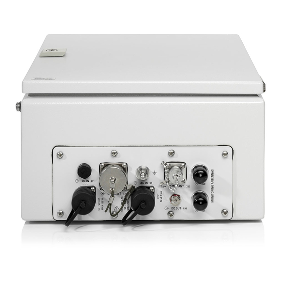
Cabling UMS100 / UMS120 Cabling All external components are connected to the connection plate at the bottom of the monitoring unit. The pin assignment of each connector is included in section 5 (Attachment A) on page 5.1. Fig. 2-17: Connection plate of UMS100/120 (without protective covers) 2.5.1 Receiving Antennas The receiving antennas are connected to X20 and/or X21 MONITORING ANTENNAS, see Fig. -
Page 45: Communications Antenna
UMS100 / UMS120 Cabling NOTE: If only one antenna is connected, terminate the second socket with the supplied 50 Ω impedance. Only use the supplied connecting cables (UMS100) to connect the antennas. These cables are suitable for outdoor use, and their lengths and RF characteristics are known and taken into account in the system. -
Page 46: 10/100 Mbit/S Ethernet Interface
Cabling UMS100 / UMS120 2.5.3 10/100 Mbit/s Ethernet Interface The network cable (not supplied as standard) is connected to X10 ETHERNET, see Fig. 2-17 on page 2.20. For test purposes or initial configuration, you can plug a commercial network cable with an 8P8C modular connector (RJ45 connector) directly into the socket, i.e. -
Page 47: Fig. 2-18: Mounting The Two Semi-Collars To An 8P8C Modular Connector (Rj45 Connector)
UMS100 / UMS120 Cabling Fig. 2-18: Mounting the two semi-collars to an 8P8C modular connector (RJ45 connector) Fig. 2-19: Assembly of 8P8C modular connector with semi-collars (housing) in accordance with CODE C Insert the rear part of the 8P8C modular connector (RJ45 connector) with the two plastic semi-collars mounted into the front part of the connector in accordance with CODE C. -
Page 48: Power Supply
Cabling UMS100 / UMS120 2.5.4 Power Supply The UMS100/120 offers an AC and a DC power input. The inputs have different pin assignments so that they cannot be interchanged inadvertently. Connect the DC supply cable (10 V DC to 30 V DC) to X2 DC IN, see Fig. 2-17 on page 2.20. Connect the AC supply cable (100 V AC to 240 V AC) to X1 AC IN, see Fig. -
Page 49: Grounding
UMS100 / UMS120 Cabling 2.5.5 Grounding The UMS100/120 contains a grounding bolt on the connection plate by which the unit can be grounded in accordance with regulations, see Fig. 2-17 on page 2.20. WARNING: Prior to putting the system into operation, the unit and, if necessary, the center mast and tripod must be grounded in accordance with regulations. -
Page 50: Overvoltage Protection
Cabling UMS100 / UMS120 2.5.6 Overvoltage Protection The UMS100/120 has no built-in overvoltage protection at the power supply inputs, the communications antenna connector and the two antenna inputs. Only the Ethernet socket is protected against overvoltage. The following values apply: 7 V DC 1.5 A ≤... -
Page 51: R&S ® Ums12-H6 Dc Feed (Ums120 Only)
UMS100 / UMS120 Cabling ® 2.5.7 R&S UMS12-H6 DC Feed (UMS120 only) A special DC feed is available for the UMS120 to supply active antennas. Max. two DC feeds can be connected to a UMS120; each feed is screwed on one of the two monitoring antenna inputs. To connect the DC feed, proceed according to the instructions given in the manual supplied with the DC feed. -
Page 52: Sim Card For Gsm Communications Module
SIM Card for GSM Communications Module UMS100 / UMS120 SIM Card for GSM Communications Module For operation of the GSM interface, you need a SIM card from a local network operator. For the CDMA communications module, no SIM card is needed. NOTE: The following conditions must be fulfilled as far as network aspects are concerned: •... -
Page 53: Power Supply
UMS100 / UMS120 Power Supply Power Supply The UMS100/120 operates on AC and/or DC power supply. The unit can be connected to an AC and a DC source simultaneously. If both supplies are connected, the unit switches to DC supply when the supply voltage rises above 24 V. -
Page 55: Control And Operation
UMS100 / UMS120 Control and Operation 3 Control and Operation This section describes all steps necessary to make the unit ready for operation, i.e. for control by means of the ARGUS or ARGUS-UMS software. It also describes system configuration by means of the service tool. -
Page 56: General
General UMS100 / UMS120 General ATTENTION: Before switching the unit on, make sure that the following conditions are fulfilled: • The cover of the unit is mounted, and the unit and all equipment attached to it are securely screwed. • The venting holes are unobstructed. -
Page 57: System Overview
UMS100 / UMS120 System Overview System Overview The figure below shows the monitoring system in its simplest configuration. A control PC at the central station (right) communicates with a UMS100/120 measurement station (left) via a communications link. Larger monitoring systems may comprise one or several control PCs and UMS100/120 systems. It does not matter whether the monitoring system is made up of UMS100 units only or UMS120 units only, or whether a mixed configuration of UMS100 and UMS120 systems is used. -
Page 58: Putting Into Operation
Putting Into Operation UMS100 / UMS120 Putting Into Operation The UMS100/120 has no power switch. Switching On Switch the UMS100/120 on by plugging the AC and/or the DC cable into X1 AC IN and/or X2 DC IN on the connection plate, see Fig. 2-17 on page 2.20, or by actuating a suitable connecting/ disconnecting device on site. -
Page 59: Remote Control
UMS100 / UMS120 Remote Control Remote Control 3.5.1 General The UMS100/120 is normally controlled exclusively via the ARGUS or ARGUS-UMS software. DOCUMENTATION: Operation of the ARGUS and the ARGUS-UMS software is described in the corresponding manuals. A list with relevant manuals and descriptions is included at the beginning of this manual. -
Page 60: Network Settings, Ip Addresses
Remote Control UMS100 / UMS120 3.5.3 Network Settings, IP Addresses The network parameters stated below are factory-set and can be changed if required via the service tool, see section 3.6.5 Communication on page 3.14. The UMS100/120 does not support dynamic address allocation in a network (DHCP/dynamic host configuration protocol). -
Page 61: Setting Up A Connection
UMS100 / UMS120 Remote Control 3.5.4 Setting Up a Connection NOTE: Prior to connecting the unit to a network, consult your network administrator if necessary. Any connection errors may impair the operation of the network as a whole. Check that the IP addresses of the PC or notebook and the UMS100/120 are correct and that the correct subnet mask is used. -
Page 62: Wireless Connection
Remote Control UMS100 / UMS120 Wireless Connection A wireless connection to the UMS100/120 is set up by dialing the call number of the communications module. The PC or notebook must be connected to a modem, see Fig. 3-1 on page 3.3. The following parameters for dialing up the UMS100/120 are factory-set. -
Page 63: Configuration By Means Of Service Tool
UMS100 / UMS120 Configuration by Means of Service Tool Configuration by Means of Service Tool 3.6.1 General A number of settings for the UMS100/120, such as IP addresses, login parameters, date and time, and also firmware updates, are performed by means of the service tool. This is a web server application ®... - Page 64 Configuration by Means of Service Tool UMS100 / UMS120 Settings and modifications made on the individual pages are accepted by clicking the Submit button. The page in question is then built up again, and the new, valid data is displayed. If you change to another page after a modification without clicking the Submit button, the previous data is restored.
-
Page 65: Calling The Start Page
UMS100 / UMS120 Configuration by Means of Service Tool 3.6.2 Calling the Start Page To start the service tool, a LAN or wireless connection must be established between the service PC or notebook and the UMS100/120, and the valid IP address for this connection must be known, see section 3.5.3 on page 3.6. -
Page 66: Login
Configuration by Means of Service Tool UMS100 / UMS120 3.6.3 Login The Login page is the start page of the service tool. To access any other page, enter a valid user name and password. The following login data are factory-set: •... -
Page 67: Home
UMS100 / UMS120 Configuration by Means of Service Tool 3.6.4 Home The Home page is the first page displayed after a successful login. The "logged-in" status is indicated in the header bar. In case "Login succeeded" is not displayed in the status bar, refer to section 3.7.1 Login on page 3.33. -
Page 68: Communication
Configuration by Means of Service Tool UMS100 / UMS120 3.6.5 Communication With this page, you can configure the communications interfaces on the UMS100/120. In the LAN Connection section, you can define the IP address, the subnet mask and the gateway of the UMS100/120 Ethernet interface. -
Page 69: Ums100 Options Management
UMS100 / UMS120 Configuration by Means of Service Tool 3.6.6 UMS100 Options Management This page is used to install and remove options. To load an option file, use the Browse button to select the directory to which the option file is to be stored and enable the Install checkbox. -
Page 70: Ums120 Options Management
Configuration by Means of Service Tool UMS100 / UMS120 3.6.7 UMS120 Options Management This page is used to install and remove options. To load an option file, use the Browse button to select the directory to which the option file is to be stored and enable the Install checkbox. -
Page 71: Antenna Configuration For Ums120
UMS100 / UMS120 Configuration by Means of Service Tool 3.6.8 Antenna Configuration for UMS120 This page is used to define the receiving antennas, the RF cables and the DC feed/s (one per path). Clicking the buttons Antenna Editor and Cable Editor opens further entry pages where you can define customer-specific antennas and specific RF antennas, respectively (see sections Antenna Editor and Cable Editor below). - Page 72 Configuration by Means of Service Tool UMS100 / UMS120 result. In the example shown in Fig. 3-8 above, up to the transition frequency of 1050 MHz the values of the left path apply, since this is the antenna with the lower frequency range. From 1050 MHz onwards the correction values of the antenna and cable of the right path are taken into account.
-
Page 73: Antenna Editor
UMS100 / UMS120 Configuration by Means of Service Tool Antenna Editor Clicking the Antenna Editor button on the Antenna Configuration page, see Fig. 3-8, opens the entry page described below, where specific antenna correction values can be entered, thus defining one’s own antenna characteristic. -
Page 74: Fig. 3-10: Antenna Editor: Save Uaf File Page Of Service Tool For Ums120
Configuration by Means of Service Tool UMS100 / UMS120 Save File As Clicking the Save File As button on the Antenna Editor page, see Fig. 3-9, opens another page for storing the value pairs plus a description into an ASCII file, see Fig. 3-10. Using the computer where the service tool was started, this file can be stored either locally or in the connected network. - Page 75 UMS100 / UMS120 Configuration by Means of Service Tool Contents of a UAF file from the example in Fig. 3-9: My own antenna 2 dBµV/m Frequency;Value 800.00;5.00 1000.00;6.00 2000.00;10.00 3000.00;15.00 4000.00;20.00 5000.00;25.00 6000.00;30.00 The UAF file can be edited using a standard ASCII editor, e.g. Notepad of operating system Microsoft Windows XP.
-
Page 76: Fig. 3-11: Antenna Editor: Load Uaf File Page Of Service Tool For Ums120
Configuration by Means of Service Tool UMS100 / UMS120 Load File Clicking the Load File button on the Antenna Editor page, see Fig. 3-9, opens the page for loading the UAF file. Fig. 3-11: Antenna Editor: Load UAF File page of service tool for UMS120 Clicking the Browse button opens a window where you can select the UAF file to be loaded. -
Page 77: Cable Editor
UMS100 / UMS120 Configuration by Means of Service Tool Cable Editor Clicking the Cable Editor button on the Antenna Configuration website, see Fig. 3-8, opens the entry page described below, where specific cable correction values can be entered, thus defining one’s own cable characteristic. - Page 78 Configuration by Means of Service Tool UMS100 / UMS120 NOTE: Prior to storing make sure that there are no frequency gaps. Otherwise storing into the UMS120 memory or into a file will fail. However, missing values at the beginning or at the end are allowed. When the values are corrected for later display in ARGUS or ARGUS-UMS, the first or last valid value will be used instead of the missing value.
-
Page 79: Date And Time
UMS100 / UMS120 Configuration by Means of Service Tool 3.6.9 Date and Time This page is used to set the time information on the UMS100/120. In the Time Zone section, you can select the time zone valid for the UMS100/120 and activate automatic switchover to daylight saving time. -
Page 80: 3.6.10 Control Pc
Configuration by Means of Service Tool UMS100 / UMS120 3.6.10 Control PC The Control PC page is used to inform the UMS100/120 of the control PC data. In the IP Address field, enter the address of the control PC at the central station. For a LAN connection, this is the IP address of the network card of the control PC. -
Page 81: 3.6.11 Firmware Update
UMS100 / UMS120 Configuration by Means of Service Tool 3.6.11 Firmware Update This page is used to update the firmware installed on the UMS100/120. To download new firmware, use the Browse button to select the directory from which the update file is to be loaded. -
Page 82: 3.6.12 Web Login Account
Configuration by Means of Service Tool UMS100 / UMS120 3.6.12 Web Login Account This page is used to change the parameters for logging in to the service tool. In the User Name field, you can modify the default name. If no modification is made, the default name will be valid. -
Page 83: 3.6.13 Maintenance
UMS100 / UMS120 Configuration by Means of Service Tool 3.6.13 Maintenance This page is used for maintenance purposes. It is not needed for configuring the UMS100/120. Fig. 3-17: Maintenance page of service tool On clicking the Execute button in the Restart UMS field, a new page opens and you are prompted to confirm the command. - Page 84 Configuration by Means of Service Tool UMS100 / UMS120 On clicking the Execute button in the Create Info File field, an information file is created, and a new page opens when the information file is ready for downloading. This may take up to 60 seconds. On clicking the Download button, you are requested to specify the directory to which the information file is to be stored.
-
Page 85: 3.6.14 Help
UMS100 / UMS120 Configuration by Means of Service Tool 3.6.14 Help This page provides concise information about the individual pages of the service tool. On clicking the Open button in the Release Notes line, the corresponding PDF document opens. For this, a PDF viewer must be installed on the PC or notebook. The Release Notes include detailed information about the various firmware versions, improvements with respect to preceding versions, and corrected or known errors. -
Page 86: 3.6.15 Logout
Configuration by Means of Service Tool UMS100 / UMS120 3.6.15 Logout This page is used to log out from the service tool properly. Clicking the Logout button starts the logout process on the UMS100/120. When the UMS100/120 has returned to its normal operating state, the Login page of the service tool is displayed again. Fig. -
Page 87: Common Errors When Working With The Service Tool
UMS100 / UMS120 Common Errors When Working With the Service Tool Common Errors When Working With the Service Tool 3.7.1 Login If the status bar remains empty after logging in, this suggests that the time for terminating a service was exceeded on the UMS100/120. Normally, "Login succeeded" should be indicated in the status bar. -
Page 88: Termination Of Service Failed
Common Errors When Working With the Service Tool UMS100 / UMS120 3.7.2 Termination of Service Failed If, during login, a service could not be terminated in time on the UMS100/120, the message shown below is output. In such case, log out from the service tool. After the Login page comes up, allow ten seconds to pass, then log in again. -
Page 89: Session Already Active
UMS100 / UMS120 Common Errors When Working With the Service Tool 3.7.3 Session Already Active This page is displayed if the IP address of a UMS100/120 is entered again although a session is already active. In this case, the Terminate Session page opens, which states possible causes for this condition. Use the Terminate Session button to terminate the previous session, which is still valid but no longer accessible. -
Page 91: Maintenance And Troubleshooting
UMS100 / UMS120 Maintenance and Troubleshooting Maintenance and Troubleshooting This chapter provides information on the maintenance and servicing of a UMS100/120 and includes basic instructions for troubleshooting. 3030.3059.32-03.00... -
Page 92: Maintenance
Maintenance UMS100 / UMS120 Maintenance The UMS100/120 is rated for continuous operation. There is no routine maintenance schedule. Depending on the quantity of data stored, measurement results have to be cleaned from the memory at intervals of several days to several months, using the service tool (see section 3.6.13 Maintenance on page 3.29). -
Page 93: Preset Key
UMS100 / UMS120 PRESET Key PRESET Key The PRESET key can be used to restore certain login and LAN parameters to the factory-set values in case that settings have been lost or wrong settings have been made. Fig. 4-2 Location of PRESET key To restore settings by means of the PRESET key, proceed as follows: ⇒... - Page 94 PRESET Key UMS100 / UMS120 The factory-set values are as follows: Ethernet connection (LAN Connection) • IP address 192.168.0.31 • Subnet mask 255.255.255.0 • Default gateway none Incoming connection (Incoming Connection) • IP address 192.168.0.131 • Password Incoming Login parameters for service tool •...
-
Page 95: Status Led Of Communications Module
UMS100 / UMS120 Status LED of Communications Module Status LED of Communications Module The status LED of the communications module (standard with UMS100, optional with UMS120) signals the module's current operating status. Fig. 4-3 Location of status LED of communications module The table below explains the various states of the communications module and their indication by the status LED. -
Page 96: Troubleshooting
Troubleshooting UMS100 / UMS120 Troubleshooting Case 1: If an error occurs and the UMS100/120 system cannot be accessed from the central station by means of the ARGUS or ARGUS-UMS software, take the following steps to locate and eliminate the error: ⇒... - Page 97 UMS100 / UMS120 Troubleshooting Case 3: If it is still not possible to access the UMS100/120 system on site via the LAN cable, proceed as follows: ⇒ Disconnect both the AC and the DC power supply cable from X1 and X2 of the UMS100/120 unit.
- Page 98 Troubleshooting UMS100 / UMS120 Case 4: If the UMS100/120 system is still not accessible, proceed as follows: ⇒ Unlock the front cover of the external cabinet by means of the supplied key and remove the cover. ⇒ Unlock the front door of the inner box by means of the supplied key and open the door. ⇒...
-
Page 99: Function Test (Self-Test)
UMS100 / UMS120 Function Test (Self-Test) Function Test (Self-Test) A limited self-test can be performed on the UMS100/120 by means of the ARGUS or ARGUS-UMS software. For this purpose, the control PC must be connected to the UMS100/120 via ARGUS or ARGUS-UMS. -
Page 101: Attachment A Description Of Interfaces
UMS100 / UMS120 Attachment A Description of Interfaces Attachment A Description of Interfaces 3030.3059.32-03.00... -
Page 102: X1 Ac In
Attachment A Description of Interfaces UMS100 / UMS120 X1 AC IN The X1 AC IN male socket is used for supplying the UMS100/120 with AC power. Type Binder Series 693 Signal Description Phase (100 V AC to 240 V AC) Not used Not used Neutral conductor... -
Page 103: X10 Ethernet
UMS100 / UMS120 Attachment A Description of Interfaces X10 ETHERNET The X10 ETHERNET socket is used for wire-bound communication between a control or service PC and the UMS100/120. Type 8P8C modular socket (RJ45 socket) Signal Description Transmit signal, plus Transmit signal, minus Receive signal, plus Not used Not used... -
Page 104: X30 Comm. Ant
Attachment A Description of Interfaces UMS100 / UMS120 X30 COMM. ANT. The X30 COMM. ANT. socket is used for connecting an external communications antenna to the UMS100/120 for wireless communication between a control or service PC and the UMS100/120. Type N socket Signal Description...
Need help?
Do you have a question about the R&S UMS100 and is the answer not in the manual?
Questions and answers