
Related Manuals for Rohde & Schwarz R&S ENV216


Summary of Contents for Rohde & Schwarz R&S ENV216
- Page 1 R&S ENV216 ® Two Line V-Network Betriebshandbuch English manual follows first colour divider 5201.6693.14 – 03.00...
- Page 2 ® Dieses Betriebshandbuch ist für folgende Modelle R&S ENV216 und Optionen gültig: ® R&S ENV216, Bestellnummer ● 3560.6550 ● ● ● ● ● © 2008 Rohde & Schwarz GmbH & Co. KG 81671 München, Deutschland Gedruckt in der Bundesrepublik Deutschland - Änderungen vorbehalten - Daten ohne spezifizierte Fehlergrenzen, Messunsicherheitsgrenzen oder Messunsicherheiten stellen nur Größenordnungen dar.
- Page 3 Certified Quality System DIN EN ISO 9001 : 2000 DIN EN 9100 : 2003 DIN EN ISO 14001 : 2004 DQS REG. NO 001954 QM UM QUALITÄTSZERTIFIKAT CERTIFICATE OF QUALITY CERTIFICAT DE QUALITÉ Sehr geehrter Kunde, Dear Customer, Cher Client, Sie haben sich für den Kauf eines you have decided to buy a Rohde &...
- Page 4 Rohde&Schwarz Adressen Firmensitz, Werke und Tochterunternehmen Weltweite Niederlassungen Firmensitz Auf unserer Homepage finden Sie: www.rohde-schwarz.com ◆ ROHDE&SCHWARZ GmbH & Co. KG Phone +49 (89) 41 29-0 Vertriebsadressen Mühldorfstraße 15 · D-81671 München Fax +49 (89) 41 29-121 64 ◆ Serviceadressen P.O.Box 80 14 69 ·...
- Page 5 Customer Support Technischer Support – wo und wann Sie ihn brauchen Unser Customer Support Center bietet Ihnen schnelle, fachmännische Hilfe für die gesamte Produktpalette von Rohde & Schwarz an. Ein Team von hochqualifizierten Ingenieuren unterstützt Sie telefonisch und arbeitet mit Ihnen eine Lösung für Ihre Anfrage aus - egal, um welchen Aspekt der Bedienung, Programmierung oder Anwendung eines Rohde &...
- Page 6 Grundlegende Sicherheitshinweise Lesen und beachten Sie unbedingt die nachfolgenden Anweisungen und Sicherheitshinweise! Alle Werke und Standorte der Rohde & Schwarz Firmengruppe sind ständig bemüht, den Sicherheitsstandard unserer Produkte auf dem aktuellsten Stand zu halten und unseren Kunden ein höchstmögliches Maß an Sicherheit zu bieten. Unsere Produkte und die dafür erforderlichen Zusatzgeräte werden entsprechend der jeweils gültigen Sicherheitsvorschriften gebaut und geprüft.
- Page 7 Grundlegende Sicherheitshinweise Versorgungs- Anzeige Gleichstrom DC Wechselstrom Gleichstrom/- Gerät durchgehend spannung Stand-by Wechselstrom durch doppelte/- EIN/AUS DC/AC verstärkte Isolierung geschützt Die Einhaltung der Sicherheitshinweise dient dazu, Verletzungen oder Schäden durch Gefahren aller Art möglichst auszuschließen. Hierzu ist es erforderlich, dass die nachstehenden Sicherheitshinweise sorgfältig gelesen und beachtet werden, bevor die Inbetriebnahme des Produkts erfolgt.
- Page 8 Grundlegende Sicherheitshinweise 2. Bei allen Arbeiten sind die örtlichen bzw. 6. Bei bestimmten Produkten, z.B. HF-Funk- landesspezifischen Sicherheits- und Unfall- anlagen, können funktionsbedingt erhöhte verhütungsvorschriften zu beachten. Das elektromagnetische Strahlungen auftreten. Produkt darf nur von autorisiertem Fach- Unter Berücksichtigung der erhöhten personal geöffnet werden.
- Page 9 Grundlegende Sicherheitshinweise 11. Ist das Produkt nicht mit einem Netzschalter 17. Bei Verbindungen mit informationstech- zur Netztrennung ausgerüstet, so ist der nischen Geräten ist darauf zu achten, dass Stecker des Anschlusskabels als Trenn- diese der IEC950/EN60950 entsprechen. vorrichtung anzusehen. In diesen Fällen ist 18.
- Page 10 Grundlegende Sicherheitshinweise 25. Verschließen Sie keine Schlitze und 31. Griffe an den Produkten sind eine Hand- Öffnungen am Produkt, da diese für die habungshilfe, die ausschließlich für Durchlüftung notwendig sind und eine Personen vorgesehen ist. Es ist daher nicht Überhitzung des Produkts verhindern. zulässig, Griffe zur Befestigung an bzw.
- Page 11 EU Konformitätserklärung Zertifikat-Nr.: 0405 Hiermit wird bescheinigt, daß der/die/das: Gerätetyp: R&S ENV216 Benennung: Zweileiter-V-Netznachbildung Identnummer: 3560.6550.02/.03/.04/.11 mit den Bestimmungen des Rates der Europäischen Union zur Angleichung der Rechtsvorschriften der Mitgliedstaaten − betreffend elektrische Betriebsmittel zur Verwendung innerhalb bestimmter Spannungsgrenzen (73/23/EWG geändert durch 93/68/EWG) −...
- Page 12 EU-Konformitätserklärung Dieser Hinweis ist Teil der Konformitätserklärung, Zertifikat-Nr.: 0405 Da, bedingt durch den geforderten, normgerechten Aufbau nach CISPR 16 und VDE 0876, der zulässige Ableitstromgrenzwert nach EN 61010-1 und die Basisisolation eines Schutzklasse I Gerätes nicht eingehalten werden können, sind zusätzliche Maßnahmen zum Schutz gegen direktes und indirektes Berühren durch den Benutzer unbedingt erforderlich.
-
Page 13: Table Of Contents
R&S ENV216 Inhalt Inhalt 1 Sicherheitshinweis ................2 2 Kurzeinführung ................... 4 Einführung........................4 Blockschaltbild ......................5 3 Betriebsvorbereitung................6 Gerät auspacken ......................6 Gerät aufstellen......................6 Schutzerdung .......................8 Netzanschluss......................10 Betrieb an nicht genormten Spannungen ...............12 Bezugsmasse ......................13 Anschluss des Prüflings...................14 Messempfängeranschluss..................14 Messaufbau ........................15 3.10 Messbeispiel.......................17 4 Bedienung .................. -
Page 14: Sicherheitshinweis
R&S ENV216 Sicherheitshinweise 1 Sicherheitshinweise Lesen und beachten Sie unbedingt vor der ersten Inbetriebnahme die folgenden Sicherheitshinweise als Ergänzung zu den grundlegenden Sicherheitshinweisen. Unsachgemäße oder fahrlässige Handhabung kann Lebensgefahr bedeuten! Da, bedingt durch den geforderten, normgerechten Aufbau nach CISPR 16-1-2 und 16-2-1 bzw. - Page 15 R&S ENV216 Sicherheitshinweise Unsachgemäße oder fahrlässige Handhabung kann Lebensgefahr bedeuten! Vor Inbetriebnahme ist die Netznachbildung mit einem zusätzlichen Schutzleiter nach VDE0100 Teil 540 Pkt. 5 (IEC 60364-5-54) zu verbinden. Bei Steckern mit Schutzleitern muss davon ausgegangen werden, dass die Schutz- leiterverbindung sich lösen kann.
-
Page 16: Kurzeinführung
R&S ENV216 Kurzeinführung 2 Kurzeinführung 2.1 Einführung Die kompakte Zweileiter-V-Netznachbildung R&S ENV216 wird zur Störspannungs- messung an netzabhängigen Verbrauchern eingesetzt. Ihre Hauptaufgaben sind: ● Versorgung des Prüflings mit Netzspannung ● Bereitstellen einer genormten Lastimpedanz ● Definierte Abgabe der vom Prüfling erzeugten Störspannung an den Funkstörmessempfänger ●... -
Page 17: Blockschaltbild
R&S ENV216 Kurzeinführung 2.2 Blockschaltbild Betriebshandbuch 5201.6693.14 - 03.00... -
Page 18: Betriebsvorbereitung
R&S ENV216 Betriebsvorbereitung 3 Betriebsvorbereitung 3.1 Gerät auspacken Ziehen Sie die beiden Schutzhauben von Front und Rückseite ab und überprüfen Sie das Gerät sorgfältig auf eventuelle Beschädigungen. Im Schadensfall sollten Sie umgehend das zuständige Transportunternehmen verständigen und alle Verpackungsteile zur Wahrung Ihrer Ansprüche aufbewahren. Auch für einen späteren Transport oder Versand des Geräts ist die Originalverpackung von Vorteil. - Page 19 R&S ENV216 Betriebsvorbereitung Unsachgemäße oder fahrlässige Handhabung kann Lebensgefahr bedeuten! Grundsätzlich ist bei Betrieb der R&S ENV216 auf ungehinderte Luftzufuhr von unten und oben zu achten. Bei Langzeitbetrieb mit maximaler Last kann die Oberflächentemperatur >70°C werden; die Abkühlzeit ist zu beachten. Da das Gerät auf der Unterseite Lüftungsöffnungen besitzt darf es nicht unbeaufsichtigt betrieben werden und es muss auf einem nicht brennbaren Untergrund aufgestellt werden (z.B.
-
Page 20: Schutzerdung
R&S ENV216 Betriebsvorbereitung 3.3 Schutzerdung Unsachgemäße oder fahrlässige Handhabung kann Lebensgefahr bedeuten! Der Betrieb des Gerätes ohne Schutzleiter ist lebensgefährlich. Der Hinweis in Kapitel 1 „Sicherheitshinweis“ ist unbedingt zu beachten! Unsachgemäße oder fahrlässige Handhabung kann Lebensgefahr bedeuten! Vor Inbetriebnahme ist die Netznachbildung mit einem zusätzlichen Schutzleiter nach VDE0100 zu verbinden. - Page 21 R&S ENV216 Betriebsvorbereitung CAUTION ACHTUNG (Hoher Ableitstrom -ca. 800 mA) age current of approx. 800 mA) n the following order: Inbetriebnahme in folgender Reihenfolge: ns network to protective earth 1. Netznachbildung mit zusätzlichem Schutzleiter verbinden nector 2. Netzstecker mit dem zu speisenden Netz verbinden ctor in socket of supplying network Außerbetriebnahme: in the following order:...
-
Page 22: Netzanschluss
R&S ENV216 Betriebsvorbereitung 3.4 Netzanschluss Der Netzanschluss erfolgt über ein fest verbundenes Netzkabel. Das Gerät besitzt keinen EIN / AUS-Schalter. Zur Trennung vom Netz dient der Gerätestecker der Anschlussleitung (siehe hierzu auch entsprechenden Abschnitt bei den grundlegenden Sicherheitshinweisen). Unsachgemäße oder fahrlässige Handhabung kann Lebensgefahr bedeuten! Bei der Inbetriebnahme ist unbedingt folgende Reihenfolge einzuhalten: Netznachbildung mit zusätzlichem Schutzleiter verbinden Netzstecker mit dem zu speisenden Netz verbinden... - Page 23 R&S ENV216 Betriebsvorbereitung L1-LED, Phasenindikator Der Schukostecker des Netzkabels kann durch einen länderspezifischen Adapter angepasst werden. Es ist jedoch darauf zu achten, dass die Strombelastbarkeit des Adapters mindestens 16 A beträgt. Die Montage ist von fachlich qualifiziertem Personal durchzuführen. Betriebshandbuch 5201.6693.14 - 03.00...
-
Page 24: Betrieb An Nicht Genormten Spannungen
R&S ENV216 Betriebsvorbereitung 3.5 Betrieb an nicht genormten Spannungen Für Messaufgaben an Spannungen außerhalb der üblichen Netzspannungsbereiche (z.B. <90 VAC) und für den Betrieb an Gleichspannungen (max. 50 VDC) wird die Steuerung der Netznachbildung über ein mitgeliefertes Steckernetzteil extern versorgt. Ein Nichtbeachten kann zur Beschädigung des Gerätes führen. -
Page 25: Bezugsmasse
R&S ENV216 Betriebsvorbereitung 3.6 Bezugsmasse Die Netznachbildung ist zwar über das Netzkabel mit dem Schutzleiter PE des Stromnetzes verbunden, dieser ist jedoch für HF-Störspannungsmessung als Bezugsmasse (Messerde) ungeeignet. Die verwendete Bezugsmasse kann über eine breite Blechfolie mit drei M4 Schrauben (1) flächig an die seitlich angebrachte Masseschiene (2) angeschlossen werden. -
Page 26: Anschluss Des Prüflings
R&S ENV216 Betriebsvorbereitung 3.7 Anschluss des Prüflings Der Prüfling wird mit seinem Netzkabel an der frontseitigen Steckdose (1) der R&S ENV216 angeschlossen. Der maximal zulässige Dauerstrom beträgt 16 A. Bei Umgebungstemperaturen von >35 °C wird eine externe Zwangsbelüftung empfohlen. Die Hochfrequenz-Störspannungsmeßebene befindet sich an der Frontplatte der R&S ENV216. -
Page 27: Messaufbau
R&S ENV216 Betriebsvorbereitung 3.9 Messaufbau Die Zweileiter-V-Netznachbildung R&S ENV216 erfüllt die Forderungen der Störmessvorschriften CISPR 16-1-2 und 16-2-1 bzw. EN55016-1-1 und EN55016-2-2 und der amerikanischen FCC (Part 15). Die in den einzelnen Normen vorgeschriebenen Messaufbauten gleichen sich weitgehend. Eine detaillierte Beschreibung liefert beispielsweise die Norm CISPR 14-1 bzw. - Page 28 R&S ENV216 Betriebsvorbereitung Pos. Funktion Messempfänger Anschluss Bezugsmasse Anschluss Messempfänger Anschluss Prüfling Prüflinge, die über einen besonderen Erdanschluss verfügen und nicht über mitge- führte Schutzleiter angeschlossen werden, werden mit einer zusätzlichen Verbindungs- leitung geerdet. Diese wird an die Masse-Buchse (1) rechts neben der Schukodose angeschlossen und parallel zur Netzleitung verlegt.
-
Page 29: Messbeispiel
R&S ENV216 Betriebsvorbereitung 3.10 Messbeispiel Die Abbildung zeigt den Messaufbau zur Störspannungsmessung an einer Handbohrmaschine. Die Handbohrmaschine wird hier an drei Metallfolien angeschlossen. Pos. Funktion Metallwand, mindestens 2 m x 2 m Prüfling Anschlussleitung Getrennt verlegte Verbindungsleitung zur Handnachbildung Netznachbildung berührbarer Metallkragen Messempfänger Anschluss Stromversorgung... -
Page 30: Bedienung
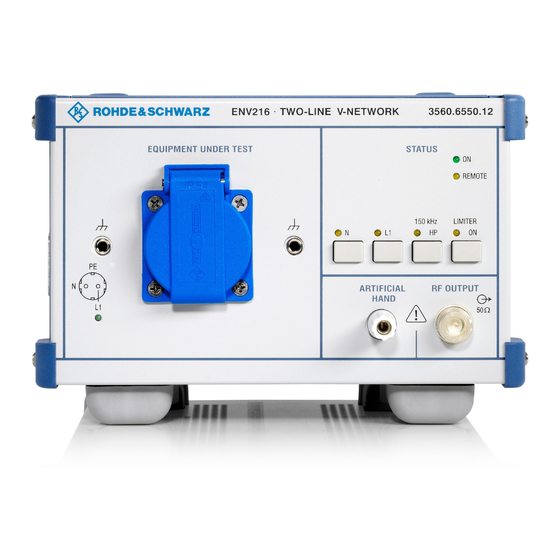
R&S ENV216 Bedienung 4 Bedienung 4.1 Elemente der Frontplatte 1 EQUIPMENT UNDER TEST L1 INDICATOR Anzeige für die korrekte Zuordnung von L1 und N zu den Messkanälen. Die LED „L1“ leuchtet, wenn der Netzstecker richtig gepolt ist. (siehe auch Inbetriebnahme) SCHUKO- Steckdose zum Anschluss des Prüflings STECKDOSE... - Page 31 R&S ENV216 Bedienung 2 STATUS Die LED zeigt die Betriebsbereitschaft der Netznachbildung an. REMOTE Die LED zeigt an, dass eine Fernsteuer- Funktion aktiv ist. (Siehe auch Kapitel 5 „Fernsteuerung“) Die LED erlischt selbstständig wenn alle Fernsteuerfunktionen inaktiv sind oder die Schnittstelle nicht belegt ist.
- Page 32 R&S ENV216 Bedienung 150 kHz HP Mit der Taste kann ein 150 kHz Hochpass in den Messpfad geschaltet werden. Es können damit Störspannungen im niederfrequenten Bereich, z.B. aus Schaltnetzteilen, unterdrückt werden. Die zugehörige LED leuchtet, wenn das Filter aktiv ist. Die Taste ist gesperrt, wenn die LED „REMOTE“...
- Page 33 R&S ENV216 Bedienung 3 RF OUTPUT RF OUTPUT Die Buchse „RF OUTPUT“ ist der Störspannungs-Messausgang zum Anschluss des Messempfängers. Am „RF OUTPUT“ liegt das Störspannungs- spektrum des gewählten Pfades um 10 dB reduziert an. Das 10 dB Dämpfungs- glied sowie ein Transientenschutz sind permanent geschaltet.
- Page 34 R&S ENV216 Bedienung Die Buchse ist eine 4 mm Aparate- klemme. (Siehe dazu auch unter Kapitel 3 Messbeispiel) Betriebshandbuch 5201.6693.14 - 03.00...
-
Page 35: Elemente Der Rückplatte
R&S ENV216 Bedienung 4.2 Elemente der Rückplatte CAUTION ACHTUNG (High leakage current of approx. 800 mA) (Hoher Ableitstrom -ca. 800 mA) Put unit into operation in the following order: Inbetriebnahme in folgender Reihenfolge: 1. connect artificial mains network to protective earth 1. - Page 36 R&S ENV216 Bedienung CAUTION ACHTUNG (High leakage current of approx. 800 mA) (Hoher Ableitstrom -ca. 800 mA) Put unit into operation in the following order: Inbetriebnahme in folgender Reihenfolge: 1. connect artificial mains network to protective earth 1. Netznachbildung mit zusätzlichem Schutzleiter verbinden using additional connector 2.
- Page 37 R&S ENV216 Bedienung 5 EXTERNAL POWER SUPPLY Extern Power Anschluss für Steckernetzteil. Über Supply den Anschluss „EXTERNAL POWER SUPPLY“ wird die Steuerung der Netznachbildung mit Strom versorgt, wenn die Netznachbildung für Mes- sungen an Wechselspannungen unterhalb 90 VAC und an Gleichspan- nungen bis 50 VDC genutzt werden soll.
-
Page 38: Fernsteuerung
R&S ENV216 Fernsteuerung 5 Fernsteuerung Die Funktionen L1, N und 150 kHz HP können durch Anlegen eines statischen LOW- Pegels am betreffenden Kontakt der SUB-D25- Buchse (1) auf der Rückseite der R&S ENV216 ferngesteuert werden. CAUTION (High leakage current of approx. 800 mA) Put unit into operation in the following order: Inbetriebnahme in fo 1. - Page 39 R&S ENV216 Fernsteuerung Impulsbegrenzung Der Impulsbegrenzer (Limiter) ist nicht fernsteuerbar. Aus Sicherheitsgründen ist der Impulsbegrenzer bei Fernsteuerung eingeschaltet. Bei vermuteter Beeinflussung des Störspektrums durch Impulsbegrenzung kann manuell nachgemessen werden Ersatzschaltbild der Fernsteuerschnittstelle Kontaktbelegung: Remote Schnittstelle Funktion 25-pol RS232 TTL (+5V) Betriebshandbuch 5201.6693.14 - 03.00...
-
Page 40: Wartung
R&S ENV216 Wartung 6 Wartung Das Gerät bedarf keiner periodischen Wartung. Die Wartung beschränkt sich im Wesentlichen auf eine Außenreinigung des Gerätes. Es ist jedoch empfehlenswert, die Solldaten von Zeit zu Zeit zu überprüfen. 6.1 Gerätesicherheitsprüfung Eine Gerätesicherheitsprüfung der Netznachbildung im Sinne der BGV A3 ist, bedingt durch den geforderten, normgerechten Aufbau nach CISPR 16-1-2 und 16-2-1 bzw. -
Page 41: Messung Des Schutzleiterwiderstandes
R&S ENV216 Wartung Während der Messung ist die Leitung abschnittsweise über die ganze Länge zu bewegen. Wird während des Bewegens der Leitung eine Widerstandsänderung festgestellt, so ist durch eine detaillierte Fehlersuche der Fehler zu lokalisieren. Defekte Leitungen dürfen nicht geflickt werden. Sie müssen unbedingt ausgetauscht werden. -
Page 42: Außenreinigung
R&S ENV216 Wartung 6.4 Außenreinigung Die Außenreinigung des Gerätes wird zweckmäßig mit einem weichen, nicht fasernden Tuch vorgenommen. Ein Nichtbeachten kann zur Beschädigung des Gerätes führen. Keinesfalls Lösungsmittel wie Nitroverdünnung, Azeton und ähnliches verwenden, da sonst die Frontplattenbeschriftung oder auch Kunststoffteile Schaden nehmen. 6.5 Lagerung und Verpackung Der Lagertemperaturbereich des Gerätes beträgt –40 bis +70°C. -
Page 43: A Anschlüsse In Länderspezifischen Ausführungen
R&S ENV216 Anlage Anlage A Anschlüsse in Länderspezifischen Ausführungen Deutschland sowie Österreich, Finnland, Niederlande, Norwegen, Russland, Schweden; gelegentlich Portugal, Spanien R&S ENV216 3560.6550.12 UK sowie Irland, Hongkong, Malaysia, Singapur R&S ENV216 3560.6550.13 Frankreich sowie Belgien und Tschechien R&S ENV216 3560.6550.14 China und Australien sowie Neuseeland R&S ENV216 3560.6550.15... - Page 44 R&S ENV216 ® Two Line V-Network Operating Manual 5201.6693.14 – 03.00...
- Page 45 ® The Operating Manual describes the following R&S ENV216 models and options: ® R&S ENV216, order number ● 3560.6550 ● ● ● ● ● © 2008 Rohde & Schwarz GmbH & Co. KG 81671 Munich, Germany Printed in Germany – Subject to change – Data without tolerance limits is not binding. ®...
- Page 46 Certified Quality System DIN EN ISO 9001 : 2000 DIN EN 9100 : 2003 DIN EN ISO 14001 : 2004 DQS REG. NO 001954 QM UM QUALITÄTSZERTIFIKAT CERTIFICATE OF QUALITY CERTIFICAT DE QUALITÉ Sehr geehrter Kunde, Dear Customer, Cher Client, Sie haben sich für den Kauf eines you have decided to buy a Rohde &...
- Page 47 Address List Headquarters, Plants and Subsidiaries Locations Worldwide Headquarters Please refer to our homepage: www.rohde-schwarz.com ◆ Sales Locations ROHDE&SCHWARZ GmbH & Co. KG Phone +49 (89) 41 29-0 Mühldorfstraße 15 · D-81671 München Fax +49 (89) 41 29-121 64 ◆ Service Locations P.O.Box 80 14 69 ·...
- Page 48 Customer Support Technical support – where and when you need it For quick, expert help with any Rohde & Schwarz equipment, contact one of our Customer Support Centers. A team of highly qualified engineers provides telephone support and will work with you to find a solution to your query on any aspect of the operation, programming or applications of Rohde &...
- Page 49 Grouped Safety Messages Make sure to read through and observe the following safety instructions! All plants and locations of the Rohde & Schwarz group of companies make every effort to keep the safety standard of our products up to date and to offer our customers the highest possible degree of safety. Our products and the auxiliary equipment required for them are designed and tested in accordance with the relevant safety standards.
- Page 50 Grouped Safety Messages Tags and their meaning DANGER DANGER indicates a hazardous situation which, if not avoided, will result in death or serious injury. WARNING WARNING indicates a hazardous situation which, if not avoided, could result in death or serious injury. CAUTION CAUTION indicates a hazardous situation which, if not avoided, may result in minor or moderate injury.
- Page 51 Grouped Safety Messages 5. If handling the product yields hazardous of the connecting cable is regarded as the substances or fuels that must be disposed of disconnecting device. In such cases, it must in a special way, e.g. coolants or engine oils be ensured that the power plug is easily that must be replenished regularly, the safety reachable and accessible at all times...
- Page 52 Grouped Safety Messages 20. For permanently installed equipment without national regulations regarding waste built-in fuses, circuit breakers or similar disposal and recycling. protective devices, the supply circuit must be 28. Please be aware that in the event of a fire, fused in such a way that suitable protection toxic substances (gases, liquids etc.) that is provided for users and products.
- Page 53 Informaciones elementales de seguridad ¡Es imprescindible leer y observar las siguientes instrucciones e informaciones de seguridad! El principio del grupo de empresas Rohde & Schwarz consiste en tener nuestros productos siempre al día con los estándares de seguridad y de ofrecer a nuestros clientes el máximo grado de seguridad. Nuestros productos y todos los equipos adicionales son siempre fabricados y examinados según las normas de seguridad vigentes.
- Page 54 Informaciones elementales de seguridad Tener en cuenta las informaciones de seguridad sirve para tratar de evitar daños y peligros de toda clase. Es necesario de que se lean las siguientes informaciones de seguridad concienzudamente y se tengan en cuenta debidamente antes de la puesta en funcionamiento del producto. También deberán ser tenidas en cuenta las informaciones para la protección de personas que encontrarán en el capítulo correspondiente de la documentación de producto y que también son obligatorias de seguir.
- Page 55 Informaciones elementales de seguridad 3. Como en todo producto de fabricación El empresario/usuario está comprometido a industrial no puede ser excluido en general de valorar y señalar áreas de trabajo en las que que se produzcan al usarlo elementos que se corra un riesgo aumentado de exposición a puedan generar alergias, los llamados radiaciones para evitar riesgos.
- Page 56 Informaciones elementales de seguridad 12. No utilice nunca el producto si está dañado el 20. En caso de que los productos que son cable eléctrico. Compruebe regularmente el instalados fijamente en un lugar sean sin correcto estado de los cables de conexión a protector implementado, autointerruptor o red.
- Page 57 Informaciones elementales de seguridad 27. Baterías y acumuladores no deben de ser de horquilla, carros etc. El usuario es expuestos a temperaturas altas o al fuego. responsable de que los productos sean Guardar baterías y acumuladores fuera del sujetados de forma segura a los medios de alcance de los niños.
- Page 58 EC Certificate of Conformity Certificate No.: 0405 This is to certify that Equipment type: R&S ENV216 Designation: Two-Line V-Network Identification No.: 3560.6550.02/.03/.04/.11 complies with the provisions of the Directive of the Council of the European Union on the approximation of the laws of the Member States −...
- Page 59 EC Certificate of Conformity This notification is part of the Conformity Declaration, Certification No. 0405 Since, based on the requisite, norm compliant structure according to CISPR 16 and VDE 0876, the permissible leakage current limit value according to EN 61010-1 and the basic insulation of a protection class I piece of equipment can not be adhered to, additional measures for protection against direct and indirect contact by the user are absolutely necessary.
- Page 60 R&S ENV216 Table of Contents Table of Contents 1 Safety directions................. 2 2 Brief introduction................4 Introduction ........................4 Block diagram ......................5 3 Preparation..................6 Unpack the device .......................6 Set up the device ......................6 Protective grounding....................8 Mains connection.......................10 Operation with non-standardized voltages.............12 Reference ground ......................13 Connecting the equipment under test ..............14 Connecting the test receiver ..................14...
-
Page 61: Safety Directions
R&S ENV216 Safety directions 1 Safety directions Before putting the product into operation make sure to read through and observe the following safety directions as addition to the basic safety instructions. Improper or negligent handling could result in death! Since the standard-compliant configuration required by CISPR 16-1-2 and 16-2-1 and also EN55016-1-1 and EN55016-2-2 means that it is not possible to limit the leakage current to the value permitted by EN61010-1, and the base insulation required for a category I protection device cannot be assured, it is imperative to provide additional... - Page 62 R&S ENV216 Safety directions Improper or negligent handling could result in death! Before using for the first time, the network must be connected to an additional conductor that is compliant with VDE0100 part 540 item 5 (IEC 60364-5-54). Users must be aware that it is possible for socket connections and grounding conductors to become disconnected.
-
Page 63: Brief Introduction
R&S ENV216 Brief introduction 2 Brief introduction 2.1 Introduction The R&S ENV216 compact Two Line V-Network is used to measure noise voltage on mains-dependent consumers. Its principal tasks are: ● To supply the equipment under test with mains voltage ● To provide a standardized load impedance ●... -
Page 64: Block Diagram
R&S ENV216 Brief introduction 2.2 Block diagram Operating Manual 5201.6693.14 - 03.00... -
Page 65: Preparation
R&S ENV216 Preparation 3 Preparation 3.1 Unpack the device Remove the two protective hoods from the front and rear and inspect the device carefully for any damage. If the device is damaged, you should notify the responsible freight carrier immediately and retain all items of packaging in order to support your complaint. - Page 66 R&S ENV216 Preparation Improper or negligent handling could result in death! The flow of air from above and below must be unimpeded at all times while the R&S ENV216 is in use. At long-term operation with maximum load the surface temperature may become >70 °C;...
-
Page 67: Protective Grounding
R&S ENV216 Preparation 3.3 Protective grounding Improper or negligent handling could result in death! Operating the device without protective earth may cause serious injury or death. The direction in chapter 1 entitled "Safety direction" must be followed without exception! Improper or negligent handling could result in death! Before using for the first time, the network must be connected to an additional conductor that is compliant with VDE0100. - Page 68 R&S ENV216 Preparation CAUTION ACHTUNG (Hoher Ableitstrom -ca. 800 mA) age current of approx. 800 mA) n the following order: Inbetriebnahme in folgender Reihenfolge: ns network to protective earth 1. Netznachbildung mit zusätzlichem Schutzleiter verbinden nector 2. Netzstecker mit dem zu speisenden Netz verbinden ctor in socket of supplying network Außerbetriebnahme: in the following order:...
-
Page 69: Mains Connection
R&S ENV216 Preparation 3.4 Mains connection Connection to the mains power supply is provided by a permanently attached mains cable. The device is not equipped with an ON / OFF switch. Instead, the device plug of the connecting cable serves for disconnection from the AC supply (for this see also the corresponding section in the basic safety instructions). - Page 70 R&S ENV216 Preparation L1 LED, phase indicator The plug on the mains cable can be adapted using a country-specific adapter. However, it must be ensured that the adapter has a power rating of at least 16 A. Assembly must be carried out exclusively by qualified technicians. Operating Manual 5201.6693.14 - 03.00...
-
Page 71: Operation With Non-Standardized Voltages
R&S ENV216 Preparation 3.5 Operation with non-standardized voltages For measurement tasks on voltages that are outside the normal mains voltage ranges (e.g. <90 VAC) and for operation on d.c. (max. 50 VDC) the R&S ENV216 control circuit is powered externally by a plug-in power supply. Failure to comply with any of these points may damage the equipment. -
Page 72: Reference Ground
R&S ENV216 Preparation 3.6 Reference ground The network is connected to the PE grounding connection for the mains power supply through the mains cable, but this is not adequate for use as a reference ground in HF noise voltage measurement. The reference ground used can be attached flat to the grounding rail (2) on the side of the device by a broad sheet metal with three metric M4 screws (1). -
Page 73: Connecting The Equipment Under Test
R&S ENV216 Preparation 3.7 Connecting the equipment under test The equipment under test is connected via the socket (1) on the front of the R&S ENV216. Constant current must not exceed 16 A. For ambient temperatures >35°C, external air ventilation is recommended. The RFI voltage measurement plane is located on the front panel of the R&S ENV216. -
Page 74: Measurement Setup
R&S ENV216 Preparation 3.9 Measurement setup The R&S ENV216 Two-Line V-Network satisfies the requirements of interference measurement regulations CISPR 16-1-2 and 16-2-1 and also EN55016-1-1 and EN55016-2-2, and the U.S. FCC (Part 15). The measurement setups prescribed in the individual standards are largely similar. A detailed description is provided for example by the standard CISPR 14-1 and EN55014-1, see also the following figure. - Page 75 R&S ENV216 Preparation Test receiver Reference ground connection Test receiver connector Test device connector Devices under test that have a separate ground connection and are not connected by integral grounding conductors are grounded using an additional connection cable. This is inserted into the ground connector (1) to the right of the test device socket and runs parallel to the mains cable.
-
Page 76: Sample Measurement
R&S ENV216 Preparation 3.10 Sample measurement The figure shows the measurement setup for measuring the RFI voltage of a handheld drill. In this example, the handheld drill is connected to three metal foils. Item Description Metal wall, at least 2 m x 2 m Equipment under test Connection cable Connection cable running separately to the hand simulation... -
Page 77: Operation
R&S ENV216 Operation 4 Operation 4.1 Elements of the front panel 1 EQUIPMENT UNDER TEST L1 INDICATOR Indicator showing the correct assignment of L1 and N to the measurement channels. LED "L1" lights up if the polarity of the mains plug is correct. (see also chapter 3 “maims connection”) EUT socket socket for connecting the equipment... - Page 78 R&S ENV216 Operation 2 STATUS This LED shows that the R&S ENV216 is powered up. REMOTE This LED shows that a remote control function is active. (See also chapter 5 "Remote control") This LED goes off automatically when all remote control functions are inactive or the port is not occupied.
- Page 79 R&S ENV216 Operation 150 kHz HP With this toggle key a 150 kHz highpass filter can be switched into the measurement path. This enables interference voltages in the low-frequency range, e.g. from switch-mode power supplies, to be suppressed. The associated LED lights up when the filter is active.
- Page 80 R&S ENV216 Operation 3 RF OUTPUT RF OUTPUT The "RF OUTPUT" socket is the RFI voltage measurement output for connec- ting the test receiver. The RFI voltage spectrum of the selected path is attenu- ated at the "RF OUTPUT" by 10 dB. The 10-dB-attenuator and a transient suppressor are permanently inserted.
- Page 81 R&S ENV216 Operation (For more information, see also "Sample measurement" in chapter 3) Operating Manual 5201.6693.14 - 03.00...
-
Page 82: Elements Of The Rear Panel
R&S ENV216 Operation 4.2 Elements of the rear panel CAUTION ACHTUNG (High leakage current of approx. 800 mA) (Hoher Ableitstrom -ca. 800 mA) Put unit into operation in the following order: Inbetriebnahme in folgender Reihenfolge: 1. connect artificial mains network to protective earth 1. - Page 83 R&S ENV216 Operation CAUTION ACHTUNG (High leakage current of approx. 800 mA) (Hoher Ableitstrom -ca. 800 mA) Put unit into operation in the following order: Inbetriebnahme in folgender Reihenfolge: 1. connect artificial mains network to protective earth 1. Netznachbildung mit zusätzlichem Schutzleiter verbinden using additional connector 2.
- Page 84 R&S ENV216 Operation 5 EXTERNAL POWER SUPPLY External Power Connection for the plug-in power Supply supply. The control circuitry of the R&S ENV216 is powered via the “EXTERNAL POWER SUPPLY" connection, if the R&S ENV216 is to be used to conduct measurements of a.c.
-
Page 85: Remote Control
R&S ENV216 Remote control 5 Remote control The functions L1, N and 150 kHz HP can be controlled remotely by applying a static LOW level to the appropriate contact of the SUB-D25 female connector (1) on the rear of the R&S ENV216. CAUTION (High leakage current of approx. - Page 86 R&S ENV216 Remote control Pulse limiting The pulse limiter is not remote controllable. For safety reasons at remote control the pulse limiter is turned on. If it is assumed, that the pulse limiting influences the noise spectrum, it can be manually remeasured. Replacement circuit diagram for the remote control port Pin assignment: Remote port Description...
-
Page 87: Servicing
R&S ENV216 Servicing 6 Servicing The device does not need to be regularly serviced. Servicing is limited essentially to wiping the device's external surfaces. However, it is recommended to check the rated specifications from time to time. 6.1 Device safety inspection A device safety inspection of the network as defined in BGV A3 is not possible because of the required, standard-compliant configuration according to CISPR 16-1-2 and 16-2-1 and also EN55016-1-1 and EN55016-2-2. -
Page 88: Measuring The Protective Earth Conductor's Resistance
R&S ENV216 Servicing During the measurement, the entire length of the wire is to be moved in sections. If a change in resistance is noted while part of the wire is being moved, the fault must be found with a detailed troubleshooting procedure. Defective cables must not be repaired. -
Page 89: Surface Cleaning
R&S ENV216 Servicing The resistance of the PE connection is calculated from the voltage reading divided by the supplied current. 6.4 Surface cleaning Cleaning the outside surfaces of the device is best performed with a soft, lint-free cloth. Failure to comply with the following may damage the equipment. Never use solvents such as nitro solvent, acetone or similar, as this will degrade the labeling on the front panel and may also damage the plastic parts. -
Page 90: A Country-Specific Connector Models
R&S ENV216 Appendix Appendix Country-specific connector models Germany as well as Australia, Finland, the Netherlands, Norway, Russia, Sweden; Occasionally: Portugal, spain R&S ENV216 3560.6550.12 UK as well as Irland, Hong Kong, Malaysia, Singapore R&S ENV216 3560.6550.13 France as well as Belgium and Czech Republic R&S ENV216 3560.6550.14 China as well as Australia and New Zealand... - Page 91 AlliCE Messtechnik GmbH make ALLICE your partner ALLICE Messtechnik GmbH Kelsterbacher Strasse 15-19 60528 Frankfurt am Main Tel.: +49(0)69-67724-583 Fax: +49(0)69-67724-582 info@allice.de www.allice.de © 2018 Allice Messtechnik GmbH – Alle Rechte vorbehalten. © 2018 Allice Messtechnik GmbH – All rights reserved Verwendete Warenzeichen und Schutzrechte sind Eigentum der jeweiligen Hersteller.
Need help?
Do you have a question about the R&S ENV216 and is the answer not in the manual?
Questions and answers